

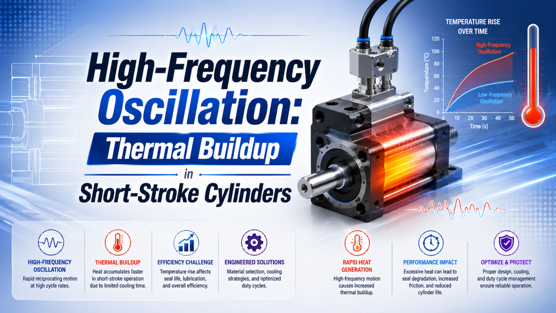
Short-stroke cylinder thermal buildup is the condition in which average heat generation exceeds the installed actuator’s ability to reject heat. Frequency alone cannot define it. Engineers must also specify whether a cycle means one move or a complete reciprocation, then account for stroke, speed profile, moving mass, end-of-stroke energy, friction, dwell, pressure, circuit layout, ambient temperature, and duty period.
This article focuses on the short-stroke oscillation energy budget. Use the broader high-cycle cylinder thermal analysis method for sensor placement and thermal time-constant testing, and the separate seal thermography guide when an infrared image needs quantitative interpretation.
Publisher and author information is available on About Us. Send technical corrections or application questions through Contact.
Key Takeaways
- ISO 19973-3 reports cylinder reliability in cycles or kilometres, not one universal hertz limit.
- A complete reciprocating cycle contains two strokes and two end events.
- Equal sliding distance per second can hide very different reversal and impact rates.
- Use the lowest model-specific temperature, speed, kinetic-energy, seal, grease, sensor, and tubing limit.
Why Doesn’t Frequency Alone Define a Cylinder’s Thermal Limit?
ISO 19973-3:2015 treats pneumatic-cylinder life in cycles or kilometres and requires declared test conditions; it does not publish a universal 2 Hz thermal boundary (ISO 19973-3, confirmed 2021). A cycle rate becomes useful only after the motion definition, cylinder model, operating conditions, and acceptance limit are stated.
Two machines can both be labelled 3 Hz while imposing different thermal loads:
- One controller may count each extension or retraction as a cycle. Another may count an extension-retraction pair.
- One axis may dwell at both ends. Another reverses immediately.
- The commanded frequency may remain constant while valve flow changes actual piston speed.
- Equal stroke and frequency can still produce different end velocities because acceleration profiles differ.
- A nearby oven, guard, mounting bracket, or exhaust jet can change heat rejection without changing cycle rate.
SMC publishes a dedicated high-speed/frequency cylinder manual for a specific CM2 variant. Its operating-frequency table is tied to named bore and stroke combinations and to a piston speed of 2500 mm/s. The same manual warns that the tube temperature depends on the pneumatic circuit, operating conditions, and environment (SMC CM2 high-speed/frequency cylinder manual, accessed 2026).
That is the correct boundary. A manufacturer’s frequency table applies to the product, circuit, pressure, stroke, speed, load, mounting, and test conditions behind the table. It is not a category-wide rule for every compact, guided, rodless, or conventional cylinder.
Treat hertz as an event counter, not a heat rating. The event count must be paired with the mechanical and pneumatic energy handled by each event. Otherwise, a precise value such as 4 Hz describes the controller command while saying little about where energy is dissipated.
Heat Enters and Leaves Through Several Paths
Carneiro and de Almeida evaluated heat transfer in three industrial pneumatic actuators and found that heat conductance varies with pressure, temperature, and actuator speed (Heat transfer evaluation of industrial pneumatic cylinders, 2007). A measured surface temperature therefore represents the combined result of heat generation, internal transfer, and rejection to the installed machine.
The main energy paths are:
- Seal, bearing, and guide friction. Sliding resistance converts mechanical work into heat. The amount depends on actual resisting force, total sliding distance, lubrication, seal preload, alignment, pressure, surface condition, and speed.
- End-of-stroke deceleration. Cushion restrictions, elastomer bumpers, external stops, shock absorbers, and machine structure absorb moving-load energy. Where that energy goes determines which part heats.
- Gas compression, filling, expansion, and exhaust. Chamber gas can heat and cool within one cycle. A gas transient is not the same as cylinder-surface or seal temperature.
- Valve and line restrictions. Pressure loss and exhaust behaviour affect motion, chamber pressure, and cushion entry speed. They do not automatically turn every lost pneumatic watt into cylinder-body heat.
- External heat transfer. Mounts, guards, process tooling, radiant sources, ventilation, and ambient temperature can dominate the surface reading.
The gas process needs its own boundary. A trapped chamber may support a closed-mass polytropic approximation, while a powered stroke with an open valve requires mass flow and energy balances. The polytropic-process guide explains that distinction. For exhaust cooling and frost, use the separate adiabatic-expansion analysis.
How Do Stroke and Frequency Set the Sliding-Distance Rate?
SMC defines its high-speed/frequency table at 2500 mm/s, showing why frequency must be tied to piston speed and stroke (SMC CM2 manual, accessed 2026). For a complete reciprocation, seals and guides travel two stroke lengths, so total sliding distance per second can be calculated before discussing heat.
If is stroke in metres and is complete reciprocating cycles per second:
is sliding distance per complete cycle, and is total sliding distance per second. The second equation remains an elapsed-time average when the cycle includes dwell. It does not reveal peak piston speed or acceleration.
If the mean resisting force over extension and retraction is defensibly represented by , a first screening estimate of friction power is:
is estimated average friction heat in watts when force is in newtons and distance rate is in metres per second. The estimate assumes the measured or modelled resistance represents the complete path. It does not assign all heat to one seal or one visible surface.
Consider two complete-cycle commands:
| Motion | Sliding distance per second | End events per second |
|---|---|---|
| 25 mm stroke at 5 Hz | 250 mm/s | 10 |
| 125 mm stroke at 1 Hz | 250 mm/s | 2 |
Both motions produce the same total sliding distance per second. The short-stroke axis has five times as many end events. If seal resistance is comparable, sliding-friction power may be similar, but cushion, bumper, reversal, valve-switching, and acceleration losses can differ sharply.
In our experience reviewing applications, the first correction is often definitional: we write one cycle as “extend plus retract” and record dwell separately. That small step prevents a factor-of-two error when one supplier quotes single strokes per minute and another quotes complete reciprocations.
How Much Thermal Load Comes From Reversal and End-of-Stroke Energy?
An SMC compact high-power cylinder manual specifies 0.05 to 0.5 m/s piston speed and allowable kinetic energy from 0.11 to 0.52 J across four listed sizes (SMC CQE manual, accessed 2026). Those model-specific values show why moving mass and end velocity belong beside frequency.
For each end event:
is kinetic energy before deceleration at end , is the equivalent moving mass, and is measured or calculated speed at cushion entry. Because velocity is squared, a speed change can matter more than a similar percentage change in cycle rate.
For one complete cycle with cap-end and rod-end events:
is the mechanical energy handled by both end events per second. It is not automatically cylinder heat. Some energy can leave with exhaust air or be absorbed by an external shock absorber, machine stop, load, or structure.
Use the actual cylinder manufacturer’s cushion-capacity chart before treating internal cushioning as a continuous high-frequency energy sink. The load-mass versus velocity cushion chart explains how to read model-specific boundaries. For a first calculation, the Pneumatic Cylinder Cushion Energy Calculator can organize mass and velocity inputs, but the catalog limit remains decisive.
Listen to the motion too. A stable thermal rise accompanied by hard end impact, bounce, or changing stroke time points toward a different mechanism than a hot rod gland with normal end deceleration. Pressure and position traces make that distinction measurable.
How Should Thermal Buildup Be Measured on the Installed Machine?
Carneiro and de Almeida used a thermal time constant and experimentally determined heat conductance for three industrial actuators. Their result supports trend testing rather than one instantaneous reading (Carneiro and de Almeida, 2007). Record the actual production recipe through warm-up, stable operation or stop criterion, and cooldown.
Use the same measurement locations and settings for every comparison:
- Record local ambient temperature away from direct exhaust and radiant heat.
- Measure the rod gland or rodless sealing slot, both end caps, barrel, mounting interface, valve, and exhaust device.
- Log command, position, cycle count, both port pressures if available, and surface temperatures on synchronized clocks.
- Preserve stroke, dwell, load, pressure, valve, flow-control settings, cushion settings, guarding, and ventilation.
- Continue until the temperature approaches a repeatable plateau or reaches the predefined model-specific stop limit.
- Stop motion without moving the sensors and record the cooldown curve.
- Change one factor, then repeat the same recipe.
Compare ambient-corrected surface rise:
is the surface temperature at one named location, is local ambient temperature, and is their difference. Use degrees Celsius or kelvin consistently. This normalization does not reveal internal seal or chamber-gas temperature.
The measurement interval must suit each signal. Surface temperature normally changes more slowly than chamber pressure or piston motion, so one sample rate need not serve every channel. Document sensor response, mounting, filter settings, timestamp alignment, and uncertainty.
An infrared image is useful for locating a hot region, but it can be biased by emissivity, reflections, target size, angle, and focus. Verify a critical surface with a repeatable contact method. Do not use a synthetic thermogram or colour palette as acceptance evidence.
What Does the Temperature and Motion Trace Reveal?
A 2017 experiment on one 50 mm-bore pneumatic cylinder measured a 23 K chamber-temperature rise during compression and a 17 K drop during expansion. The same cycle can contain heating and cooling, so a barrel or seal temperature must be interpreted with motion and pressure evidence (Hassan et al., 2017).
| Observed pattern | Plausible energy path | Next verification |
|---|---|---|
| Rod gland heats more than barrel | seal friction, side load, tight guide, surface damage | alignment, side load, breakaway force, rod condition |
| One end cap heats and impact noise rises | cushion entry speed, bumper loss, hard stop | position, peak velocity, cushion pressure, moving mass |
| Both end caps warm while gland stays stable | repeated end-event dissipation | compare end energy with exact capacity chart |
| Valve or silencer is cold while cylinder warms | expansion cooling at exhaust plus separate cylinder losses | dew point, exhaust restriction, port pressures |
| Mount is hottest location | conducted process heat or restricted rejection | frame temperature, guards, airflow, standoff |
| Temperature rises after seal replacement | preload, lubricant, alignment, assembly variation | work record, breakaway force, leakage, repeat test |
| Cycle time drifts before surface temperature changes | supply, valve, flow, friction, or sensor issue | synchronized pressure and position trace |
The side-loading and seal-wear guide is the next check for a hot gland. For an end-cap pattern, inspect the cushion seal and adjustable cushioning path before changing the main piston seal.
Temperature location and timing are more diagnostic than the highest number alone. If a surface rise appears after end impact begins, the impact event deserves priority. If the thermal trace changes after a guard is installed while pressure and motion remain stable, heat rejection is the stronger hypothesis.
Corrective Actions Must Match the Measured Heat Path
One SMC compact-cylinder model is rated for -10 to 60°C, while one Festo AEVC short-stroke model lists -20 to 80°C ambient temperature. Neither range is universal (SMC CQE manual, accessed 2026; Festo AEVC-63-10 datasheet, dated 2025-10-08). Select corrective action against the exact assembly’s lowest applicable limit.
Use this order:
- Correct mechanical loading. Remove side load, binding, guide misalignment, rigid coupling error, damaged rod surfaces, and loose mounts.
- Control end energy. Reduce cushion-entry speed, moving mass, or hard-stop impact. Adjust cushions within the manufacturer’s method or add a correctly sized external shock absorber.
- Restore the pneumatic path. Check valve capacity, tube ID, fittings, speed-control direction, silencer condition, supply pressure, exhaust back pressure, and local pressure sag.
- Verify lubrication and air quality. Follow the cylinder maker’s grease and compressed-air instructions. A generic “high-temperature lubricant” is not evidence of seal, grease, or material compatibility.
- Improve heat rejection only after locating the source. Restore ventilation, remove external heat gain, add shielding, or change the mounting path. A fan can lower the surface reading while leaving excessive friction or impact unresolved.
- Select a rated cylinder option. Confirm cylinder, seal, grease, switch, fitting, tubing, cable, and nearby sensor ratings as one system.
Lowering pressure can reduce available force and sometimes change energy use, but it is not a universal thermal cure. Lower pressure may also slow motion, extend valve-open time, change cushioning, or leave too little force margin. Recalculate force and verify both port pressures before accepting the change.
High-temperature seals are not automatically lower-friction seals. Compound, geometry, surface finish, lubrication, pressure, speed, and extrusion clearance interact. Use the temperature and seal-material selection guide when measured temperature exceeds the standard option’s rating.
How Should a High-Frequency Short-Stroke Cylinder Be Specified?
ISO 19973-3 reports reliability in cycles or kilometres, while the SMC high-speed/frequency manual ties frequency to bore, stroke, circuit, and a 2500 mm/s piston-speed condition. A useful specification must therefore define the mechanical cycle, pneumatic circuit, thermal environment, and required life rather than request “5 Hz capable” by itself.
Include:
- cylinder type, bore, rod diameter, stroke, mounting, and orientation;
- whether one cycle means one move or one complete reciprocation;
- complete cycles per second, dwell at each end, and shift schedule;
- commanded and measured position-time profile;
- peak velocity and velocity at each cushion entry;
- moving mass, external force, side load, and load centre;
- supply pressure, both port pressures, valve, tubing, fittings, speed controls, and silencers;
- cushion type, setting, external stop, and shock absorber;
- ambient range, nearby heat sources, guards, washdown, and ventilation;
- required cycle life or travel life, inspection interval, and leakage criterion;
- allowable surface-temperature locations and model-specific stop conditions.
If available flow is known, the Cylinder Speed Calculator can screen extension and retraction speed. It cannot predict peak acceleration, seal temperature, or cushion-entry velocity without the actual motion and circuit.
A supplier can only evaluate thermal suitability when the test boundary is reproducible. Frequency, stroke, and pressure alone omit the energy handled at reversals and the installed path for rejecting that energy.
High-Frequency Short-Stroke Cylinder FAQs
The SMC CM2 manual lists at least nine regular inspection items, including smooth operation, cycle-time change, leakage, stroking, surface damage, and filter drainage. High-frequency thermal control is therefore a condition-monitoring task, not one temperature switch (SMC CM2 manual, accessed 2026).
Is 2 Hz high frequency for every pneumatic cylinder?
No. Two hertz means little until the cycle convention, stroke, speed profile, dwell, load, circuit, and cylinder model are known. ISO 19973-3 reports reliability in cycles or kilometres, while manufacturers publish product-specific speed, kinetic-energy, and temperature limits. Use the exact catalog and operating manual.
Does a shorter stroke always produce less heat?
No. Shorter stroke reduces sliding distance per cycle, but the machine may run more cycles and create more reversals per second. A 25 mm stroke at 5 complete cycles per second and a 125 mm stroke at 1 cycle per second both total 250 mm of sliding distance per second.
Does cylinder surface temperature equal seal temperature?
No. Surface temperature is the result of internal generation, conduction, convection, radiation, mounting, and ambient conditions. A hidden seal lip or chamber gas can be warmer or cooler than the accessible housing. Name the measurement point and verify critical infrared readings with a repeatable contact sensor.
Will reducing air pressure always reduce thermal buildup?
No. Lower pressure changes force margin, acceleration, stroke time, valve-open duration, and cushioning behaviour. It may help one machine and destabilize another. Recalculate force, record both chamber pressures, and repeat the same production-duty thermal test before accepting pressure reduction as the corrective action.
When should a high-temperature seal option be selected?
Select it after measuring the installed condition and identifying the lowest applicable rating. One SMC compact model lists -10 to 60°C, while one Festo short-stroke model lists -20 to 80°C ambient. Check the exact cylinder, seal, grease, switch, fitting, tubing, and cable together.
Sources and technical references
- ISO 19973-3:2015, Pneumatic fluid power, assessment of component reliability by testing, cylinders with piston rod, confirmed 2021, retrieved 2026-07-26.
- SMC CM2 High Speed/Frequency Cylinder Operation Manual, document CM2*-OM0300Q, retrieved 2026-07-26.
- SMC CQE Compact Cylinder High Power Type Operation Manual, document CQ2*-OM0288Q, retrieved 2026-07-26.
- Carneiro and de Almeida, Heat transfer evaluation of industrial pneumatic cylinders, 2007, retrieved 2026-07-26.
- Hassan et al., Experimental Investigation of a Temperature Change inside Pneumatic Cylinder Chambers, 2017, retrieved 2026-07-26.
- Festo AEVC-63-10-A-P-A Short-Stroke Cylinder Datasheet, dated 2025-10-08, retrieved 2026-07-26.