

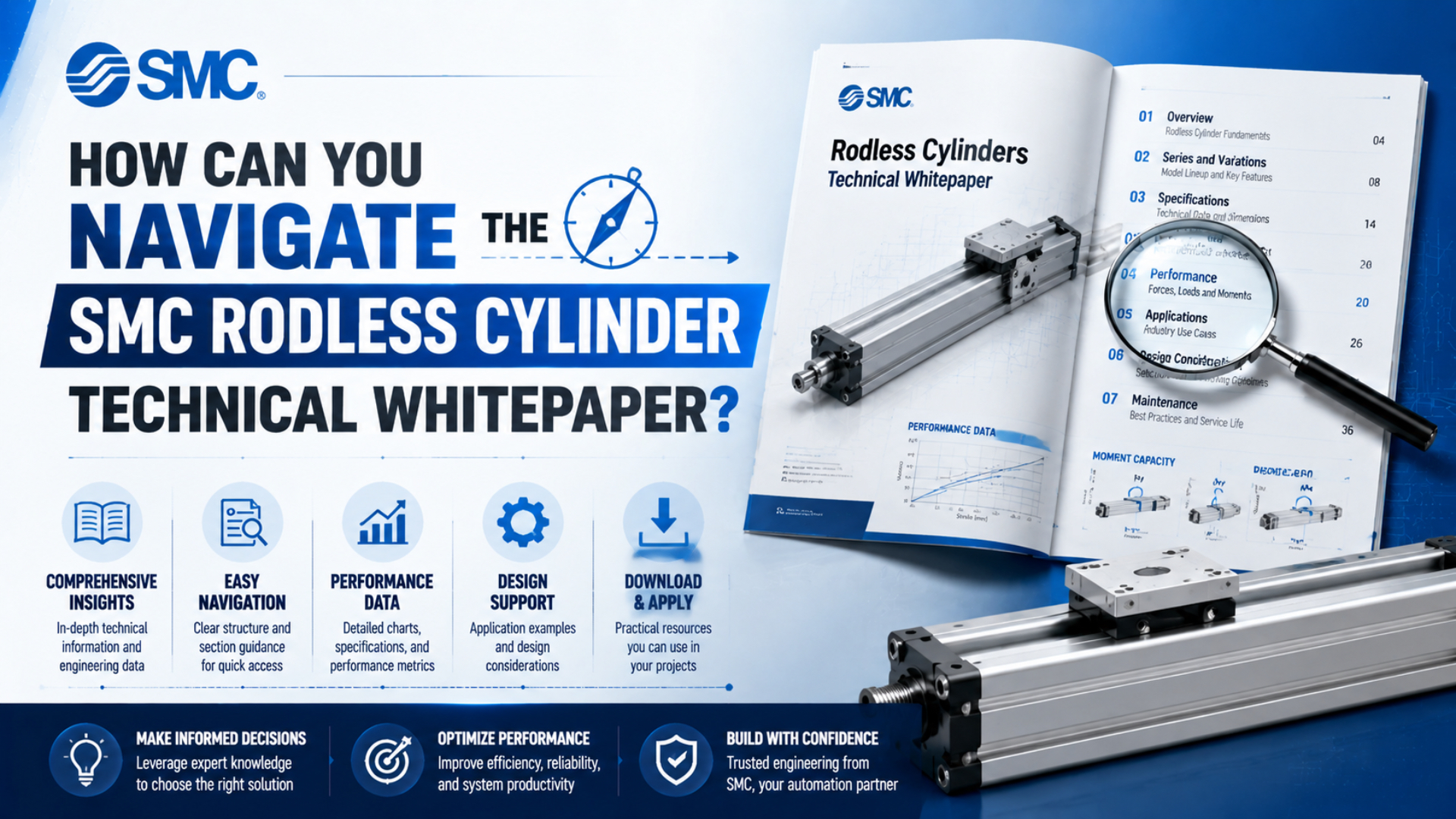
Navigate SMC rodless cylinder technical data as a document set, not as one universal whitepaper. Start with the exact series, generation, bore, stroke, piping arrangement, and option code. Then use the matching model-selection pages, specifications, dimensions, CAD, precautions, manuals, and maintenance records for that configuration.
This order prevents a familiar error: finding a drawing that looks right, then applying ratings from another bore, guide type, or product generation. The catalog is useful only when every extracted value remains tied to the same full part number and document revision.
Key Takeaways
- SMC’s current MY1B page covers 25, 32, and 40 mm bores.
- The new MY1B keeps earlier mounting dimensions while raising maximum load and moment ratings by up to 30%.
- Dimensional fit, rated duty, controls, and service documents must be checked separately.
In this guide
- What does the technical whitepaper actually mean?
- Start with the exact series and generation
- Use the right SMC document for each task
- Read the ordering page before the drawings
- Interpret MY1B mounting dimensions safely
- Check performance after confirming fit
- Control CAD, manuals, and revisions
- Build a replacement or RFQ worksheet
- Resolve catalog and installed-cylinder conflicts
- SMC technical-data FAQs
What Does “SMC Rodless Cylinder Technical Whitepaper” Actually Mean?
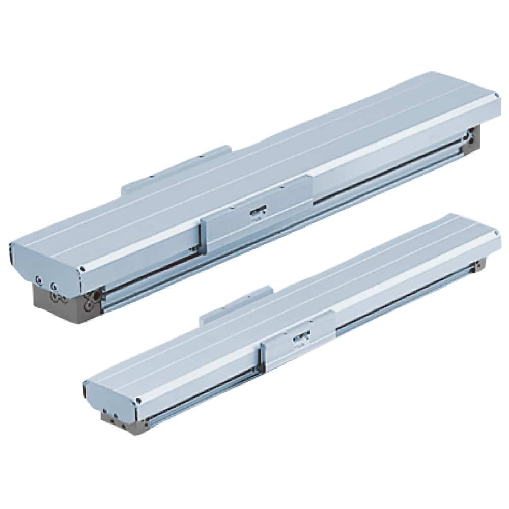
SMC’s current MY1B page lists three bores, 25, 32, and 40 mm, and links separately to model selection, technical data, quick-selection tables, CAD, manuals, and precautions (SMC MY1B Web Catalog, accessed 2026-07-27). Treat those linked resources as the working technical package.
An SMC rodless cylinder technical package is the controlled set of documents needed to identify, size, install, and service one exact configuration. It is not whichever catalog page appears first in a search.
There is no single file that answers every selection, installation, control, and maintenance question. The useful package normally includes:
- a product-family page for series scope and current status;
- a How to Order section for the model code;
- model-selection pages for load, moment, speed, and cushioning;
- specifications for pressure, temperature, stroke, ports, and lubrication;
- dimension drawings for each bore and option;
- 2D or 3D CAD for machine-layout work;
- actuator, auto-switch, and product-specific precautions;
- manuals and maintenance-parts information for service tasks.
The page title can still use the familiar word “whitepaper,” but the engineering method is different. Identify the question first, then open the document that controls that question. A dimension sheet cannot replace the model-selection method, and a CAD file cannot establish the allowable load.
A catalog search is complete only when the engineer records both the value and its source location. “Height = 28 mm” is weak evidence. “Dimension H = 28 mm for the stated bore, piping type, option code, catalog revision, and page” is reviewable evidence.
Start With the Exact Series and Generation
SMC’s CAD search currently returns 13 MY1B-related entries, including legacy bores from 10 to 100 mm and newer MY1B-Z entries for 25, 32, and 40 mm (SMC CAD System, accessed 2026-07-27). The family name alone therefore does not identify one drawing.
First separate the coupling architecture:
| Family | SMC description | Identification consequence |
|---|---|---|
| MY series | Mechanically jointed rodless cylinder | Uses a slit, internal seal belt, and external dust seal band |
| CY series | Magnetically coupled rodless cylinder | Transfers motion through magnetic coupling across a closed tube |
| REA series | Sine rodless cylinder, double acting | Pneumatic specialty cylinder, not an electric actuator |
SMC explains that the MY table connects mechanically through a tube slit, while the CY external slider follows an internal magnet assembly (SMC Rodless Cylinder FAQ, accessed 2026-07-27). Those architectures have different leakage, contamination, overload, and recovery behaviour.
A mechanical-joint rodless cylinder is an actuator whose external carriage connects physically to its piston through a sealed longitudinal slit. A magnetically coupled cylinder keeps the tube closed and transfers motion through magnets.
Do not use a CY3R drawing to answer an MY1B mounting question. Likewise, do not treat REA as an electric-actuator family. If the nameplate is unreadable, identify the coupling type, profile, carriage, ports, sensor rail, guide arrangement, and end hardware before selecting a document.
Generation matters inside one family. SMC states that the updated MY1B keeps the mounting dimensions of the existing MY1B while increasing maximum load mass and allowable moment by as much as 30% (SMC MY1B New Product Information, updated 2025). Same mounting dimensions do not mean identical ratings.
The guide to rodless-cylinder coupling technologies provides a deeper comparison of mechanical-joint and magnetic designs.
Use the Right SMC Document for Each Engineering Task
The MY1B Web Catalog exposes at least six distinct resource groups: product-number check, catalog, digital catalog, CAD, manual, and model-selection or technical-data links (SMC MY1B Web Catalog, accessed 2026-07-27). Select the resource by decision, not by whichever PDF appears first in search.
| Engineering question | Primary document | What to record |
|---|---|---|
| Is this the correct family? | Web Catalog and product page | Series, type, generation, bore range, current status |
| What does the model code mean? | How to Order | Bore, stroke, piping, thread, switch, option and made-to-order suffix |
| Can it carry the load? | Model Selection/Technical Data | Load, moment axes, speed, centre-of-gravity offsets and combination rule |
| Will it fit? | Dimension drawing and CAD | Envelope, carriage, mounting, ports, sensor and service clearances |
| Can it stop the load? | Cushion and stroke-adjustment data | Entry speed, energy, absorber model, adjustment range and frequency |
| How is it installed or serviced? | Precautions, manual and parts list | Alignment, tightening, residual-pressure, inspection and replacement instructions |
Searching inside a PDF works best after this map is clear. Use the exact series and field name, such as “allowable moment,” “standard stroke,” “piping,” “shock absorber,” or a dimension symbol. A search for only “MY1B” can return ordering, legacy, and new-generation pages without showing which one controls your cylinder.
Read the How to Order Page Before the Dimension Drawings
The legacy MY1B catalog spans ten nominal bores from 10 to 100 mm, while the current MY1B-Z1 page lists 25, 32, and 40 mm (SMC CAD System, accessed 2026-07-27). Decode the full installed code before choosing a dimension page or CAD model.
Create an identity record with these fields:
- Series and generation: MY1B, MY1B-Z, MY1B-Z1, or another exact designation.
- Bore: the size symbol must match the dimension and rating pages.
- Stroke: record the ordered stroke, not only the measured exposed travel.
- Piping arrangement: standard and centralized piping can change port details.
- Port thread: distinguish M, Rc, NPT, and G where the catalog offers them.
- Auto switch: include switch model, quantity, lead wire, connector, and mounting hardware.
- Stroke-adjustment unit: record the unit and shock-absorber selection.
- Made-to-order suffix: copy every suffix and retrieve its separate specification.
Do not reconstruct a part number from memory. Copy it from the nameplate, quotation, machine bill of materials, or controlled drawing, then decode it against the matching How to Order page. A missing suffix can conceal a long-stroke body, special thread, material change, or adjustment unit.
When the installed label and machine record disagree, keep both observations. Mark one as physical evidence and the other as document evidence. The conflict must be resolved before a drawing or rating is approved.
How Do You Interpret MY1B Mounting Dimensions Safely?
SMC says the updated MY1B retains existing mounting dimensions while maximum load mass and allowable moment rise by up to 30% (SMC MY1B New Product Information, updated 2025). This proves that mounting equivalence and performance equivalence are separate engineering checks.
Use the dimension drawing in four passes:
- Envelope: overall length, body height and width, carriage height, end-cover envelope, adjustment-unit projection, and switch clearance.
- Mounting: hole count, thread, counterbore, pitch, locating face, end support, carriage pattern, and floating-bracket interface.
- Pneumatic interface: port size, port direction, alternate plugged ports, cushion-needle access, and tube or fitting clearance.
- Service envelope: bowl-free space does not apply here; instead reserve room for seal-band inspection, switch removal, shock-absorber replacement, fasteners, and carriage travel.
Dimension letters are local to a specific drawing or table. Do not assume that an H, L, or P symbol means the same thing in another series. Record the symbol, value, unit, bore, option, page, and revision together.
The article on finding cylinder height for rodless applications explains how to separate profile height, carriage height, installed stack height, and clearance. For replacement work, compare every decisive interface rather than one overall-height value.
In our experience reviewing replacement applications, the fastest dimensional check is a marked comparison drawing. Our team found that one colour can identify equal dimensions, another can mark deviations, and a third can expose missing supplier data. From our work on these reviews, the value is speed: the drawing does not approve the cylinder, but it exposes unresolved fit questions before hardware reaches the machine.
Which Performance Pages Matter After the Cylinder Fits?
The current 25, 32, and 40 mm MY1B catalog specifies 0.1 to 0.8 MPa operating pressure, 5 to 60°C ambient and fluid temperature, and 100 to 1,000 mm/s piston speed without a stroke-adjustment unit (SMC MY1B Catalog, accessed 2026-07-27).
Those limits belong to the named current models and conditions. They are not universal values for every MY1B generation, option, or application.
| Catalog field | Application input required | Common reading error |
|---|---|---|
| Operating pressure | Dynamic pressure at the cylinder during motion | Using only the regulator’s static setting |
| Piston speed | Required speed in both directions | Assuming a needle-valve setting proves the actual speed |
| Load mass | Moving mass and orientation | Ignoring externally guided or cantilevered mass |
| Allowable moment | Force and centre-of-gravity offsets in three axes | Checking mass while omitting pitch, roll, or yaw |
| Cushion or absorber | Mass, approach speed, energy and cycle rate | Selecting by bore without the impact condition |
| Auto switch | Logic, voltage, wiring, position and PLC timing | Checking groove fit only |
| Temperature | Ambient, fluid and nearby heat sources | Applying a room-temperature rating to a hot enclosure |
MY1B is a basic mechanical-joint cylinder. The machine may rely on a separate guide to carry transverse load and moments. The actuator drawing cannot certify the external rail, mounting parallelism, bracket stiffness, or combined system accuracy.
Flow control also needs its own evidence. Meter-out control can stabilize pneumatic motion, but the required valve capacity depends on bore, target speed, pressure, tubing, fittings, load, and exhaust conditions. Use the separate guide to proportional flow-control valves in rodless-cylinder systems instead of a bore-only valve matrix.
For dynamic checks, review pressure drop at cylinder ports and fittings and internal air-cushion energy limits.
How Should You Access CAD, Manuals, and Revision-Controlled Files?
SMC’s current MY1B page states that PDF catalog downloads and 2D or 3D CAD require registered access, while its CAD service can output several formats using full part numbers (SMC MY1B Web Catalog, accessed 2026-07-27). Plan access before an urgent replacement.
For every downloaded file, record:
- official source URL and regional site;
- page title and exact series;
- download date;
- file name and revision or issue date;
- language;
- bore, stroke, piping, switch, and option scope;
- pages used for the engineering decision;
- who reviewed the extraction.
A distributor copy can help when the official portal is unavailable, but verify its revision against the manufacturer’s current product page. Search-engine snippets, forum attachments, screenshots, and isolated CAD files are leads, not controlled selection evidence.
CAD answers geometry questions. It may omit seals, internal flow paths, detailed tolerances, material specifications, load limits, shock-absorber capacity, and product precautions. Keep the CAD model linked to its catalog and model-selection record.
A controlled catalog value is a number stored with its symbol, unit, operating condition, exact model scope, document page, revision, and reviewer. Without that identity, even an accurately copied value can be applied to the wrong cylinder.
Turn the Catalog Into a Replacement or RFQ Worksheet
The 2025 MY1B update kept existing mounting dimensions while increasing load and moment limits by up to 30%, which shows why a replacement worksheet needs both interfaces and ratings (SMC MY1B New Product Information, updated 2025). A cross-reference based on profile shape is incomplete.
Build one row for each requirement:
| Requirement | Installed evidence | SMC document field | Acceptance result |
|---|---|---|---|
| Exact identity | Nameplate, machine BOM, purchase record | How to Order and current product page | Match, conflict, or unknown |
| Envelope and mounting | Measured installation and machine drawing | Bore- and option-specific dimension page | Dimension-by-dimension result |
| Pneumatic interfaces | Port gauge, tube and fitting record | Port and piping-option details | Thread, position and clearance result |
| Load and moments | Mass, centre-of-gravity offsets and orientation | Model-selection data | Calculation and margin |
| Speed and stopping | Cycle trace, approach speed and stop hardware | Speed, cushion and absorber pages | Rated and measured result |
| Sensing | Switch code, PLC logic and timing | Auto-switch compatibility pages | Electrical and position result |
| Environment | Temperature and contamination record | Specifications and precautions | Within scope or supplier review |
| Service | Access, wear parts and maintenance method | Manual and maintenance-parts list | Approved task and stocked parts |
The final RFQ should attach the full incumbent code, marked drawing, application data, photographs, sensor requirements, and acceptance limits. Ask the supplier to identify every deviation rather than using the phrase “drop-in replacement.”
The existing guide to SMC rodless cylinder alternatives covers cross-brand evidence and machine trials. Use this article first to extract the incumbent specification, then use that replacement guide to evaluate a candidate.
The best catalog worksheet is reusable after purchasing. The same identity, interface, duty, sensing, and service fields can become incoming-inspection criteria and a commissioning record. This avoids a common handoff gap in which engineering selects one configuration but maintenance receives only a short purchasing description.
What Should You Do When the Catalog and Installed Cylinder Disagree?
SMC’s CAD search still lists legacy MY1B bores from 10 to 100 mm, whereas the current MY1B-Z1 page lists only 25, 32, and 40 mm (SMC CAD System, accessed 2026-07-27). A mismatch can reflect generation, region, option, or incomplete records.
Use this resolution order:
- Photograph the full nameplate and every visible suffix.
- Check the machine bill of materials, drawing, purchase record, and maintenance history.
- Identify mechanical-joint, magnetic, or sine-cylinder construction.
- Measure only decisive external interfaces with calibrated tools.
- Compare the official current page, applicable legacy catalog, CAD entry, and made-to-order specification.
- Send the unresolved identity evidence to SMC or the responsible supplier.
- Record the final series, revision, deviations, and approval basis in the machine file.
Do not choose the nearest drawing and force the measurements to fit it. If the generation remains unknown, state that uncertainty in the RFQ and require the supplier to close it before quotation.
Also separate catalog disagreement from machine damage. A bent bracket, shifted guide, modified port, replaced shock absorber, or locally machined mounting plate can make the installed assembly differ from its original documentation. Record modifications as installed conditions, not as manufacturer dimensions.
Publisher and engineering context is available on About Bepto. For an application review, use Contact and include the full model code, nameplate photographs, marked dimensions, operating pressure, load, speed, sensors, and unresolved catalog conflicts.
SMC Rodless Cylinder Technical Data FAQs
SMC’s current MY1B page lists three bores, while its CY3 page lists nine bores from 6 to 63 mm for CY3B and CY3R (SMC MY1B; SMC CY3, accessed 2026-07-27). Exact series and generation identification must precede every short answer below.
Is there one SMC rodless cylinder technical whitepaper?
No. SMC distributes the needed information across product pages, catalogs, model-selection data, quick-selection tables, CAD, manuals, precautions, and maintenance resources. Start from the exact series page, decode the complete model, and record which file and page supports each selected dimension or rating.
Can I use MY1B-Z1 dimensions for an older MY1B?
Only after confirming the exact incumbent generation and the dimensions involved. SMC states that the updated 25, 32, and 40 mm MY1B retains existing mounting dimensions, but that statement does not cover every legacy bore, option, accessory, port arrangement, or performance rating. Compare controlled drawings line by line.
Is a CY3R technically equivalent to an MY1B?
No. CY3R transfers motion through magnetic coupling inside a closed tube, while MY1B uses a mechanical joint through a sealed slit. The architectures differ in leakage behaviour, contamination exposure, overload response, available guidance, and selection data. Similar stroke and envelope do not make them interchangeable.
Do identical mounting dimensions prove a drop-in replacement?
No. SMC’s updated MY1B keeps existing mounting dimensions while increasing maximum load and allowable moment by up to 30%. A replacement also needs checks for guide type, pressure, speed, moments, cushioning, ports, sensors, environment, service parts, and representative machine performance.
Which SMC files should be attached to an RFQ?
Attach the series page, decoded ordering information, relevant model-selection pages, specifications, bore- and option-specific dimension drawing, and any made-to-order document. Add the installed nameplate, photographs, marked measurements, load and speed data, sensor requirements, and a list of unresolved conflicts or deviations.