

Select a pneumatic silencer by the installed result, not by thread size or a standalone noise-reduction claim. Define the acoustic target, compare ratings under equivalent test conditions, size for peak exhaust demand, set an allowable back-pressure limit, match the element to the air quality, and verify noise, pressure, and cycle time on the machine.
Festo’s Silencer U catalog shows why shortcuts fail. Three G1/8 examples are rated from 1,340 to 2,050 L/min at 6 bar, even though their connection size matches. Port compatibility is only the first check, not proof of acoustic or pneumatic suitability (Festo Silencer U, 2024).
Key Takeaways
- Freeze the acceptance target before requesting a part number.
- Compare acoustic values only when pressure, distance, and test mode are stated.
- Size the complete exhaust path for peak demand and allowable back pressure.
- Commission the silencer with noise, pressure, and stroke-time baselines.
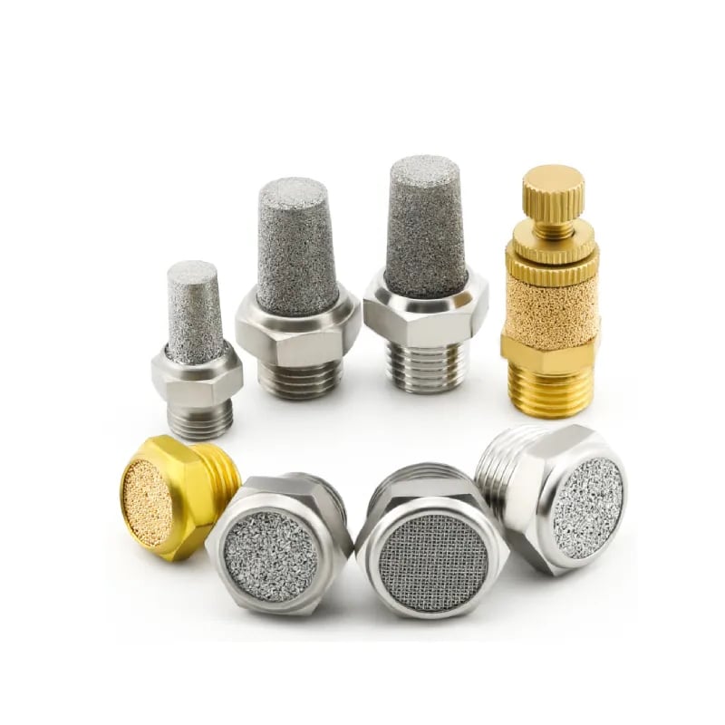
A pneumatic silencer, also called an exhaust muffler, reduces sound as compressed air leaves a valve, actuator, vacuum generator, or other exhaust port. For silencer construction and basic operating principles, start with the pneumatic muffler guide. The ten rules below focus on evidence needed for selection and acceptance.
Pneumatic silencer selection is the process of matching acoustic performance, exhaust conductance, contamination tolerance, installation constraints, and service requirements to one defined machine event.
1. What Must the Installed Silencer Actually Achieve?
SMC’s current silencer ranges publish nominal noise-reduction values from 13 to 40 dB(A) depending on product family. That spread is useful only after the engineer defines where sound will be measured, which cycle is critical, and how much exhaust restriction the machine can tolerate (SMC Silencer Variation).
Write an acceptance statement before comparing catalogs. It should specify:
- the valve or device exhaust port and thread standard;
- the operating pressure at the component during the critical cycle;
- the load, stroke, cycle rate, and simultaneous exhaust events;
- the sound metric, microphone location, and machine state;
- the maximum allowable exhaust-port pressure;
- the maximum allowable extension or retraction time;
- the air-quality class, oil exposure, ambient temperature, and washdown conditions;
- the permitted envelope, orientation, service access, and replacement method.
Do not convert an OSHA exposure action level into a silencer specification. A workplace exposure assessment combines duration, distance, multiple sources, reflections, and worker location. The component requirement may need to be stricter or may address only one contributor.
The most useful silencer “rating” is a paired result: acoustic performance at an identified operating point and pneumatic performance at the same installed cycle. A quiet part that delays exhaust beyond the machine’s timing limit has not met the requirement.
2. Why Is a Product dB Rating Not a Workplace Exposure Result?
OSHA requires a hearing-conservation program when employee exposure equals or exceeds an 8-hour time-weighted average of 85 dB(A). NIOSH also uses 85 dB(A) as its recommended exposure limit, with allowable duration halving for each 3 dB increase (OSHA 1910.95; NIOSH).
A manufacturer’s sound-pressure value describes a component under stated conditions. It does not automatically predict the operator’s dose beside a complete machine. The installed result changes with:
- microphone distance and orientation;
- upstream pressure and exhaust pulse duration;
- background noise and other synchronized exhausts;
- walls, guards, floors, and reflective enclosures;
- mechanical end impact, vibration, and structure-borne sound;
- duty cycle and worker time at the station.
Use the component value for like-for-like screening. Use a calibrated workplace measurement for occupational decisions. If a silencer produces little improvement, identify whether the dominant source is actually exhaust noise. The pneumatic valve acoustic guide separates jet noise, pressure pulsation, resonance, and mechanical impact.
3. How Do You Compare Acoustic Data Without Mixing Test Conditions?
ISO 20145:2026 defines two acoustic measurement methods for pneumatic exhaust silencers: a steady-state method using constant upstream pressure and a discharge method during upstream pressure decrease. Results from those modes describe different events and should not be treated as interchangeable (ISO 20145:2026).
Record these fields beside every candidate value:
| Catalog field | Why it changes the comparison |
|---|---|
| Test method or standard | Steady flow and transient discharge can produce different acoustic results |
| Upstream and downstream pressure | Pressure ratio changes mass flow, jet structure, and event duration |
| Measurement distance and position | Sound pressure falls and directionality changes with geometry |
| Weighting and time response | dB(A), unweighted bands, peak, fast, and equivalent levels answer different questions |
| Silencer model and port | Construction and effective flow area vary within one family |
| Flow state | A constant-flow result does not reproduce every cylinder exhaust pulse |
Festo states that its Silencer U sound values are measured at 6 bar relative pressure against atmosphere from 1 m. That condition makes the numbers traceable. If another datasheet omits pressure or distance, do not rank it as if the test were equivalent.
For tonal complaints or critical hearing-control work, request octave-band or one-third-octave data rather than relying on one A-weighted number. A-weighting is useful for exposure context, but it can hide the frequency band responsible for an objectionable tone or communication problem.
4. Why Must You Size for Peak Exhaust Flow Instead of Thread Size?
Festo lists G1/8 Silencer U variants at 1,340, 2,000, and 2,050 L/min, all with flow measured at 6 bar upstream. The highest published value is about 53% above the lowest, despite the shared thread size (Festo Silencer U, 2024).
Start with the exhausting chamber’s displacement-equivalent average flow from bore, rod diameter, stroke, pressure, and target time. For a screening relationship:
Here, is free-air flow in L/min, is the effective area of the chamber exhausting during that stroke in mm², and is piston speed in mm/min. and are representative absolute chamber conditions. and define the same standard reference used by the catalog. The factor converts mm³ to liters.
This equation gives a displacement-based average, not the instantaneous exhaust peak. Initial blowdown from pressurized dead volume and connected tubing, chamber pressure decay, temperature change, and simultaneous exhausts can raise the peak. Final selection therefore needs model-specific transient or compressible-flow data plus installed pressure and timing verification.
Use the flow converter when supplier data and plant measurements use different reference units. Do not compare NL/min, SLPM, SCFM, and actual L/min until their standard temperature and pressure bases are understood.
The choked-flow guide explains why lowering downstream pressure cannot increase mass flow indefinitely. It also explains why a silencer should be evaluated as part of the controlling effective passage, not as a cosmetic accessory.
5. Which Flow Data Are Better Than a Generic Cv Shortcut?
ISO 6358-1 specifies steady-state methods for pneumatic components and uses compressible-flow characteristics such as sonic conductance. SMC’s current AN documentation likewise publishes sonic conductance or effective area for silencer models, allowing pneumatic comparisons in the manufacturer’s stated framework (ISO 6358-1; SMC AN Series).
Prefer data in this order:
- an exhaust-flow or discharge curve for the exact model and relevant pressure range;
- ISO 6358 sonic conductance and critical pressure ratio;
- effective area or an equivalent manufacturer pneumatic-flow parameter;
- a stated flow value with upstream pressure and reference conditions;
- a controlled installed comparison when the catalog evidence is incomplete.
A generic liquid-style Cv equation is not sufficient for transient compressed-air exhaust. It can hide absolute-pressure requirements, reference-state conversions, critical flow, downstream pressure, temperature, and the manufacturer’s test convention. If only Cv is available, ask the supplier for the gas-flow method and assumptions before approving the part.
Port size still matters mechanically, but it does not reveal the active internal passage. The port size versus internal orifice analysis shows why two components with the same connection can have different flow limits.
6. How Much Exhaust Back Pressure Can the Machine Accept?
SMC warns that silencer noise reduction varies with the pneumatic circuit and operating pressure. Its documentation also pairs acoustic values with flow characteristics, reinforcing that noise and exhaust restriction must be evaluated together rather than as separate purchases (SMC AN Series).
There is no universal allowable back-pressure number. Establish the limit from the machine’s slowest acceptable loaded stroke, force margin, valve behavior, safety function, and exhaust-path layout. Measure pressure dynamically at the exhausting cylinder port or the closest practical upstream point while recording stroke time.
Do not raise supply pressure simply to conceal a restrictive silencer. That response can increase air consumption, stored energy, leakage, impact, and the severity of the next exhaust pulse. First reduce the restriction or select a higher-conductance model, then restore the circuit to its validated operating pressure.
The pneumatic back-pressure guide explains how exhaust pressure subtracts from the useful pressure difference across a moving piston. For component-level measurement, use the valve pressure-drop procedure.
7. Trace Each Exhaust Direction and Every Shared Path
A double-acting cylinder has two exhaust directions, and manifold designs can combine multiple valve exhausts into one shared passage. ISO 4414 treats pneumatic safety and maintenance at system level, which is the correct boundary for tracing those interacting paths before selection (ISO 4414).
Mark the circuit in each machine state:
- which cylinder chamber is exhausting;
- which valve exhaust port is active;
- whether a meter-out control sits upstream of the silencer;
- whether adapters, tubing, or a manifold gallery add series restriction;
- whether pilot exhaust is separate from main exhaust;
- which other valves discharge into the same gallery at that instant.
Then evaluate the worst coincidence. A silencer that supports one cylinder on a bench can become the limiting element when three manifold stations vent together. If only one direction slows after installation, investigate the exhaust route for that direction before changing the supply regulator.
The correct silencer flow requirement belongs to an exhaust event, not merely to a valve port. An event includes the pressurized volume, starting pressure, valve state, simultaneous branches, target discharge time, and every series restriction between the chamber and atmosphere.
8. How Should Air Quality Change the Silencer Construction?
ISO 8573-1 classifies compressed-air purity by particles, water, and oil. Those three contaminant groups affect silencer elements differently, so “oil-resistant” is incomplete before a material is selected unless the supplier also states compatibility, drainage behavior, allowable orientation, and maintenance instructions (ISO 8573-1).
Match the failure mechanism to the environment:
| Exposure | Selection concern | Evidence to request |
|---|---|---|
| Solid particles or pipe scale | Pore blockage and falling conductance | Filtration requirement, pore or mesh design, cleanability |
| Condensed water | Corrosion, swelling, freezing, and drainage | Material, temperature range, orientation, drain path |
| Oil aerosol | Coating of porous media and environmental discharge | Oil compatibility, exhaust-cleaner requirement, disposal method |
| Washdown chemicals | Polymer or adhesive degradation | Chemical compatibility for the exact concentration and temperature |
| Outdoor or cold service | Ice formation and brittle materials | Minimum temperature and validated material limits |
A silencer is not automatically an oil-mist separator. SMC explicitly cautions that exhaust containing oil or oil mist can disperse to the environment and directs users to an exhaust cleaner where collection is required (SMC AN Series).
If an element clogs repeatedly, treat contamination at the source. Check compressor carryover, dryer performance, filter condition, low-point drainage, lubricator setting, and ambient ingress. The silencer-clogging diagnostic guide shows how to verify restriction with pressure and timing rather than appearance.
For a narrower material decision, use the sintered bronze versus plastic silencer comparison. This rule defines the contamination and compatibility evidence; it does not rank materials by name.
9. Installation and Maintenance Rules Are Model-Specific
Festo lists optional mounting position for the cited Silencer U variants and a temperature range of minus 10 to 70°C. Those values apply to identified models under catalog conditions; they do not prove that every silencer can face any direction or survive the same environment (Festo Silencer U, 2024).
Confirm these details on the exact datasheet:
- thread type, sealing method, tightening torque, and permitted adapter;
- mounting orientation and clearance around the discharge surface;
- protection from impact, paint, tape, weld spatter, and washdown residue;
- minimum and maximum ambient and media temperature;
- whether the element is cleanable, replaceable, or disposable;
- approved cleaning fluid, drying method, and inspection limit;
- whether a guard changes the required free discharge area.
Do not assign one replacement interval to every application. Establish a clean-state baseline, trend the loaded stroke time and exhaust pressure, and replace or service the part when the machine crosses its documented limit. A calendar interval can remain as an inspection trigger, but condition evidence should determine whether the element still performs.
ISO 4414 addresses pneumatic-system safety, maintenance, and energy isolation. Before removing a silencer, stop the machine, isolate the energy source, release stored pressure, and follow the machine-specific lockout procedure (ISO 4414).
10. How Do You Prove the Selected Silencer Works on the Machine?
ISO 20145:2026 separates steady-state and discharge acoustic tests, while Festo reports catalog sound at 1 m. Installed commissioning needs the same discipline: define the operating state and sensor locations so a future measurement reproduces the original result (ISO 20145:2026; Festo Silencer U).
Run an A/B comparison with the original configuration and the selected silencer:
- Stabilize supply pressure, load, flow controls, cushioning, and machine temperature.
- Record extension and retraction time separately for repeated loaded cycles.
- Record valve-inlet pressure and exhausting-port pressure on the same time base.
- Measure sound at the specified position with the same instrument settings.
- Check abnormal impact, unstable motion, pilot-valve behavior, and adjacent stations.
- Inspect for oil mist, particles, unsafe discharge direction, and loose mounting.
- Save the part number, lot, settings, traces, and pass/fail limits as the baseline.
If the sound target is met but exhaust pressure or stroke time fails, choose a higher-conductance silencer or redesign the shared exhaust path. If pressure and timing pass but sound does not, verify the test position and identify other sources before installing a more restrictive element.
Pneumatic Silencer Selection Worksheet
The Festo G1/8 examples span 1,340 to 2,050 L/min, and SMC families span nominal noise reductions from 13 to 40 dB(A). A defensible RFQ therefore needs application data rather than one thread and one desired dB number (Festo Silencer U; SMC Silencer Variation).
Send the supplier this minimum dataset:
| RFQ field | Required entry |
|---|---|
| Exhaust source | Valve, cylinder, ejector, air motor, blow-off, or relief device |
| Connection | Thread standard, nominal size, sealing method, adapter restrictions |
| Pressure | Upstream operating range and downstream condition |
| Demand | Peak free-air flow, discharge volume, target time, simultaneous events |
| Acoustic target | Metric, location, weighting, machine state, applicable site limit |
| Pneumatic limit | Maximum exhaust pressure and maximum stroke or discharge time |
| Air quality | ISO 8573-1 class if known; oil, water, particle, and chemical exposure |
| Environment | Temperature, washdown, corrosion, vibration, impact, outdoor exposure |
| Installation | Orientation, envelope, free outlet area, service access |
| Evidence | Test method, model-specific flow data, materials, maintenance instructions |
Ask for the exact model’s acoustic conditions, flow curve or ISO 6358 parameters, material declaration, mounting constraints, and cleaning or replacement instructions. Then make purchase approval conditional on the installed A/B test.
Pneumatic Silencer Selection FAQs
ISO 20145:2026 recognizes two silencer acoustic test modes, and one Festo G1/8 family spans 1,340 to 2,050 L/min at 6 bar. These answers address the recurring decisions that thread-size charts and standalone dB claims cannot resolve (ISO 20145; Festo Silencer U).
Can I select a pneumatic silencer by thread size alone?
No. Thread size proves mechanical compatibility, but models with the same connection can have different internal passages, materials, acoustic ratings, and flow capacity. Compare model-specific sound conditions, sonic conductance or effective area, contamination limits, and installed back pressure before approving an interchangeable part.
What noise-reduction rating should I request?
Start with the installed sound target, microphone position, machine state, and critical exhaust event. Then compare products tested under equivalent pressure, distance, weighting, and ISO 20145 mode. A standalone reduction value cannot predict worker exposure or the contribution from mechanical impact and other simultaneous sources.
How do I know whether a silencer is restricting cylinder speed?
Record loaded stroke time and exhausting-port pressure, then substitute an identical clean, known-good silencer without changing supply, load, flow controls, or cushioning. Restriction is confirmed when exhaust pressure falls and the affected stroke time improves together. Sound or visual appearance alone is not sufficient evidence.
Is an oil-resistant silencer also an oil-mist separator?
Not necessarily. Oil-resistant materials may tolerate lubricant exposure without providing aerosol collection. If exhaust can carry oil mist into the workplace, obtain the manufacturer’s environmental guidance and use a rated exhaust cleaner or recovery device where required. Also correct excessive compressor or lubricator carryover at its source.
How often should pneumatic silencers be replaced?
There is no universal replacement interval. Record clean-state exhaust pressure, loaded cycle time, and installed sound, then trend those values under comparable conditions. Inspect on a planned schedule, but service or replace the exact model according to its instructions when performance crosses the machine’s documented acceptance limit.
Need help comparing two silencer datasheets or preparing an RFQ? Send the exhaust source, pressure, peak-flow estimate, air quality, installation photos, and acceptance limits through our technical contact page.