

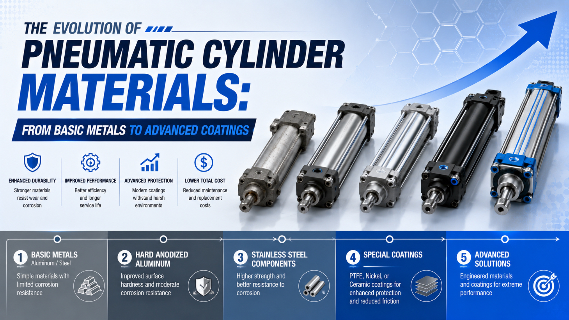
Pneumatic cylinder materials evolved from comparatively simple metal assemblies into component-specific systems that combine aluminum or stainless structures, engineered rod and bore surfaces, polymer seals, bearing materials, and localized coatings. The change was not a straight race toward the hardest or newest material. It was a shift toward assigning each surface one defined mechanical, sealing, corrosion, or manufacturing job.
ISO 15552 shows why material claims need a boundary. The standard covers detachable-mounting cylinders from 32 mm to 320 mm bore at a maximum rated pressure of 1,000 kPa, yet its purpose is dimensional interchangeability rather than prescribing one construction material (ISO 15552:2018). Two interchangeable cylinders can therefore use very different material packages.
Key Takeaways
- ISO 15552 standardizes a 32-320 mm dimensional series, not one material recipe.
- Specify each component, substrate, finish, thickness, and final dimension separately.
- Protective anodizing, hard anodizing, PEO, chromium, nickel-phosphorus, and DLC are not interchangeable.
- Laboratory hardness, friction, and salt-spray results do not predict complete-cylinder life by themselves.
A pneumatic cylinder material package is the documented combination of substrates, surface treatments, seal compounds, guides, lubricants, fasteners, and acceptance requirements used in one actuator configuration. Material selection starts at component level. The pneumatic cylinder coating guide handles present-day harsh-environment coating selection; this article explains how the architecture reached that point.
How Did Pneumatic Cylinder Materials Evolve From Steel to Hybrid Assemblies?
ISO 15552 covers cylinders from 32 mm to 320 mm bore at up to 10 bar, but it standardizes basic and mounting dimensions rather than a historical material sequence. The practical evolution occurred inside that envelope: manufacturers changed substrates, profiles, finishes, seals, and guides while preserving usable interfaces (ISO 15552).
Early industrial designs often concentrated structure, pressure containment, and wear resistance in metal parts. Tie rods clamped machined end covers around a tube. Steel provided strength and familiar manufacturing routes, while paint, plating, oil, and maintenance controlled corrosion and wear. That architecture remains valid where loads, repairability, or established plant standards favor it.
Extruded aluminum profiles changed the design space. A profile could combine the pressure tube, switch grooves, mounting features, and external shape in one part. An anodic oxide layer protected the exterior, while the bore received a finish compatible with the piston seal. Less machining and fewer separate features helped create lighter, modular cylinder families.
Stainless construction expanded where moisture, cleaning chemicals, product contamination, or damaged exterior finishes made a barrier coating insufficient. It did not eliminate the mixed-material cylinder. Stainless barrels and rods still work beside polymer seals, bearing materials, lubricants, magnets, fittings, and sometimes aluminum or engineering-plastic internal parts.
The latest stage is selective surface engineering. Chromium, electroless nickel-phosphorus, carbon-based films, ceramic-containing composites, and other systems can be applied to a defined part or surface. The functional layer may be only one element in a stack that includes substrate preparation, an interlayer, the main coating, finishing, and post-treatment.
The useful definition of “advanced” is not newest, hardest, or most expensive. A material system is advanced when it puts the required property on the correct surface without damaging pressure integrity, seal behavior, dimensions, manufacturability, or repairability.
Which Material Belongs on Each Cylinder Component?
A Festo cylinder datasheet combines a smooth-anodized wrought-aluminum barrel, high-alloy steel or stainless rod choices, aluminum covers, polymer seals, and guide materials in one product. That is four material systems inside one actuator, which is more representative than assigning the cylinder a single material label (Festo datasheet).
Start with the job performed by each component:
| Component or surface | Primary material job | Selection questions | Acceptance evidence |
|---|---|---|---|
| Cylinder barrel structure | Contain pressure and preserve geometry | Alloy, wall section, extrusion or tube process, ports, fatigue boundary | Material identity, dimensions, pressure test, traceability |
| Barrel exterior | Resist handling, moisture, chemicals, cleaning and scratches | Exposure, pretreatment, anodizing or coating system, damaged-edge behavior | Process specification, thickness where relevant, visual criteria |
| Finished bore | Guide the piston seal with controlled form and texture | Diameter, cylindricity, roughness, coating sequence, porosity, lubricant | Final dimensional and surface inspection after treatment |
| Piston rod substrate | Carry axial load and resist bending or impact | Steel grade, stainless grade, strength, corrosion mechanism, repair route | Material certificate, straightness, hardness where specified |
| Rod running surface | Work with the rod seal and wiper | Finish family, final texture, thickness, cracks, pores, adhesion | Final roughness, coating inspection, seal compatibility test |
| Piston and guides | Transfer force and control contact | Aluminum, steel, POM, PTFE composite or another bearing material | Clearance, wear allowance, temperature and lubricant compatibility |
| Dynamic and static seals | Retain pressure over motion and dwell | Exact compound, profile, speed, temperature, air chemistry, grease | Compound declaration, drawing, batch or supplier traceability |
| End covers and fasteners | Close pressure and transfer mounting load | Alloy, thread strength, galvanic couples, washdown exposure | Material and finish specification, torque and pressure test |
A barrel can be corrosion resistant outside and still fail internally from wet compressed air. A hard rod can still destroy a seal if its final texture is wrong. A stainless end cover can still create a weak point when paired with unsuitable fasteners, fittings, sensors, or mounting hardware.
The cylinder seal material guide covers compound-level selection. The honed cylinder tube guide explains why bore geometry and finish need their own inspection plan.
A Component-Level Material Map Prevents Single-Label Decisions
The Festo datasheet identifies at least four material systems in one standards-based cylinder: anodized aluminum, steel or stainless rod material, polymer seals, and separate guide materials. A component map turns that mixed construction into inspectable boundaries instead of one vague “aluminum” or “stainless” label (Festo datasheet).
Why Did Anodized Aluminum Replace So Much Painted Steel?
Two ISO scopes govern aluminum anodizing: ISO 7599 covers decorative and protective oxidation, while ISO 10074 covers hard oxidation for engineering wear and abrasion. This split shows why “anodized aluminum” is not a complete pneumatic cylinder specification (ISO 7599; ISO 10074).
Aluminum profiles can integrate tube geometry, switch slots, mounting features, and external form. Anodizing converts the surface rather than laying a separate metallic plate over it. For example, one profile can replace a plain tube plus separately machined sensor and mounting features. Those manufacturing advantages made aluminum attractive for standardized and modular factory-automation cylinders.
The substrate alloy, temper, extrusion quality, machining, pretreatment, anodizing process, sealing, and final finishing still matter. A dark color does not prove hard anodizing. A specified layer thickness does not by itself prove the bore diameter, surface texture, abrasion behavior, or corrosion performance required after finishing.
Protective anodizing and hard anodizing also serve different priorities. ISO 7599 excludes hard anodic coatings used mainly for engineering abrasion and wear, directing that work to ISO 10074. ISO 10074, in turn, explicitly excludes plasma electrolytic oxidation and related micro-arc processes. Calling all three “advanced Type III” erases their different process and acceptance routes.
For a cylinder barrel, separate the exterior from the bore:
- Exterior: appearance, handling damage, cleaning chemicals, moisture, edge coverage, electrical contact, and mounting interfaces.
- Bore: final diameter, cylindricity, roughness, coating defects, lubricant retention, piston-seal wear, and repair feasibility.
- Machined threads and ports: coating buildup, masking, sealing faces, plug fit, and damage after assembly.
An aluminum cylinder is not automatically light enough, corrosion resistant enough, or suitable for washdown. Compare complete designs, including wall section, end covers, tie rods, mounts, accessories, and protection at every exposed interface.
For a controlled bore-wear comparison rather than this historical overview, use the hard-anodized versus standard barrel test guide.
When Is Stainless Steel Construction Better Than a Coating?
Festo identifies two stainless-steel grades, 1.4301 and 1.4401, in its corrosion-resistant cylinder range and warns that a resistant system involves more than selecting steel. Mounting parts, accessories, seals, lubricant, geometry, and cleaning exposure remain inside the decision (Festo corrosion-resistant cylinders).
Stainless construction is valuable when scratches, cleaning, condensation, or chemical exposure could penetrate a barrier finish and expose a vulnerable substrate. It can simplify damaged-surface behavior and reduce reliance on continuous paint or plating. It is also useful when product-contact or cleanability requirements demand controlled external materials and geometry.
It is not immunity. Stainless steel can pit, suffer crevice corrosion, gall at threads, or interact badly with chlorides, cleaners, deposits, and dissimilar metals. Grade identity, surface condition, fabrication, weld treatment, passivation or electropolishing, drainage, and cleaning chemistry all affect the installed result.
A “stainless cylinder” may also be only partly stainless. Confirm the material of:
- barrel and piston rod;
- front and rear covers;
- rod nut, tie rods, mounting bolts, pins, clevises, and trunnions;
- cushioning needles, retaining rings, and sensor hardware;
- fittings, silencers, tubing connections, and cable glands;
- seals, wipers, guides, grease, and thread compounds.
Use stainless construction when the exposure requires substrate-level resistance or when a damaged coating would be difficult to detect and repair. Use a coated or anodized aluminum package when weight, profile integration, cost, or a proven protective system fits the declared environment better. The washdown corrosion guide develops the exposure and drainage checks.
Rod and Bore Surface Engineering Became a Separate Material System
ISO 6158:2018 is the fourth edition of the engineering chromium standard and provides a designation route for chromium thickness on ferrous or non-ferrous substrates. That is a narrower and more useful specification than “chrome rod,” because substrate, undercoat, thickness, finishing, and significant surfaces remain identifiable (ISO 6158).
The piston rod carries mechanical load, but its outermost surface runs through the rod seal and wiper. Those are separate duties. A substrate may supply strength and straightness while a finish supplies corrosion behavior, hardness, texture, or wear resistance.
Engineering chromium remains one rod-surface option. Stainless steel rods, hardened stainless grades, induction-hardened or plated steels, electroless nickel systems, thermal-spray systems, and carbon-based films may be considered when the application and manufacturing route justify them. Each changes the inspection plan.
The final rod needs more than a coating name:
| Rod requirement | Why it matters |
|---|---|
| Substrate grade and condition | Controls strength, toughness, machinability and response to finishing |
| Straightness and diameter | Affect bearing load, seal alignment, friction and mounting behavior |
| Finish type and thickness | Define the functional surface and dimensional allowance |
| Final roughness and texture | Influence lubricant film, seal wear, leakage and contamination transport |
| Cracks, pores and adhesion | Create corrosion paths or release debris |
| Edge and thread treatment | Prevent assembly damage and uncontrolled buildup |
| Repair and replacement rule | Determines whether a damaged surface can be restored safely |
The bore has the same layered logic. Honing before coating is not equivalent to honing or polishing after coating. A treatment can change diameter, form, texture, porosity, and seal clearance. The drawing must identify the condition in which each dimension and roughness requirement applies.
In our drawing reviews, the most useful clarification is often the inspection state. Does the diameter or roughness apply before coating, after deposition, or after final grinding? A correct substrate certificate and a correct coating certificate can still produce a rejected cylinder when the finished rod or bore misses its dimensional and surface requirements.
What Do Electroless Nickel, DLC, and Ceramic Composites Actually Add?
Three ISO documents separate coating families: ISO 4527 covers electroless nickel-phosphorus, ISO 23363 covers Ni-P-ceramic composites, and ISO 20523 classifies carbon-based films including DLC. They require different specifications, not one generic label (ISO 4527; ISO 23363; ISO 20523).
Electroless nickel-phosphorus can deposit on metallic substrates without the current-distribution pattern of conventional electroplating. The specification still needs substrate preparation, phosphorus range or process designation where relevant, thickness, heat treatment, porosity, adhesion, finishing, and the service exposure. ISO 4527 does not cover nickel-boron, Ni-P composites, or ternary alloys.
Ni-P-ceramic composite coatings add dispersed ceramic material to a nickel-phosphorus matrix. ISO 23363 confirms that this is its own specification route. The ceramic type, distribution, matrix chemistry, thickness, finishing, and counterface determine whether the coating helps a specific rod, bore, guide, or non-sliding exterior surface.
DLC is also a family, not one material. ISO 20523 includes amorphous carbon films, CVD diamond, graphite, and polymer-like films, and it says the classification refers to the carbon-film material rather than the entire coating stack. An interlayer, gradient, dopant, deposition route, substrate temperature, thickness, and post-finish can change the installed result.
Advanced films can be useful when a validated test shows that a conventional substrate and finish cannot meet wear, friction, corrosion, cleanliness, or lubricant constraints. For instance, a qualified rod film may address a specific wear pair without changing the barrel exterior. Advanced films are poor substitutes for an undefined problem.
Before approving one, ask:
- Which exact component and surface receives the coating?
- What failure mechanism is being controlled?
- What substrate and preparation are required?
- What coating designation, thickness, interlayer, and final finish apply?
- Will deposition or heat treatment alter substrate properties or dimensions?
- Which seal, wiper, guide, lubricant, and cleaning chemistry contact it?
- What coupon, component, and assembled-cylinder tests prove acceptance?
- How will damage, repair, and replacement be handled?
No coating hardness or temperature value becomes the rating of the complete pneumatic cylinder. The lowest compatible seal, guide, grease, magnet, sensor, fitting, tube, adhesive, or mounting component can set the actual limit. For thermal applications, use the high-temperature cylinder guide to review the complete assembly.
For an application-specific treatment of HVOF carbide and oxide systems on mining rods, use the ceramic cylinder-rod coating guide.
Why Can’t Hardness, Friction, or Salt-Spray Hours Rank Complete Cylinders?
ISO 9227 defines three salt-spray methods, NSS, AASS, and CASS, but explicitly says they are not intended to rank different materials or predict long-term corrosion resistance. A table that converts test hours into years of cylinder life therefore exceeds the standard’s stated purpose (ISO 9227:2022).
Hardness is also method-dependent. A thin coating, soft substrate, surface curvature, indentation load, preparation, and measurement method can change the result. Reporting HRC, HV, or another scale without the test method and valid thickness range creates false comparability.
Friction coefficient depends on a pair of surfaces and a test condition. Counterface material, finish, load, speed, motion type, temperature, humidity, lubricant, contamination, and running-in all matter. A dry laboratory value cannot be transferred directly to a lubricated rod seal or piston seal.
Wear improvement is not a universal multiplier. The result belongs to the tested material pair, geometry, load, speed, environment, sliding distance, debris condition, and endpoint. Cylinder life adds alignment, pressure cycling, side load, seal design, guide clearance, stroke distribution, dwell, air quality, and maintenance.
Use laboratory tests for controlled questions:
| Test result | Defensible use | Unsafe interpretation |
|---|---|---|
| Salt-spray exposure | Detect defects or verify a named product requirement | Predict years in an unspecified plant |
| Coating hardness | Verify a process or compare qualified specimens under one method | Rank complete cylinders across different substrates |
| Pin-on-disk friction or wear | Compare material pairs under stated test parameters | Predict rod-seal friction or service life directly |
| Coating thickness | Verify deposition allowance and process compliance | Prove corrosion, adhesion or wear by itself |
| Surface roughness | Verify a named final surface and measurement method | Assume one Ra value defines the full texture |
| Pressure and leakage test | Confirm the assembled unit under stated conditions | Prove long-term chemical or wear resistance |
Test the mechanism that matters, then test the finished component, and finally validate the assembled cylinder in representative service. Skipping from coupon data to a lifetime claim is the point where most coating comparisons become unreliable.
Pneumatic Cylinder Material Package Selection Worksheet
ISO 15552 allows dimensional interchangeability across a 32-320 mm, 10 bar series, but it does not make two interchangeable cylinders materially equivalent. A procurement worksheet must therefore sit beside the dimensional drawing and identify every substrate, functional surface, exposure, inspection state, and acceptance criterion (ISO 15552).
Use this sequence before approving a standard, modified, or custom cylinder:
| Review field | Minimum information | Decision or evidence |
|---|---|---|
| Installed exposure | Temperature cycle, humidity, washdown, chemicals, particles, UV, salt, radiation where applicable | Named normal, peak and cleaning conditions |
| Mechanical duty | Bore, stroke, pressure, load, speed, cycle rate, side load, impact, mounting | Load and motion acceptance limits |
| Component map | Barrel, bore, rod, covers, hardware, seals, guides, lubricant, sensors and fittings | Material assignment for every exposed or moving part |
| Substrate specification | Alloy or grade, condition, required properties and traceability | Certificate or supplier declaration |
| Surface process | Standard, process designation, preparation, interlayers, thickness and masking | Approved process route and significant surfaces |
| Final geometry | Diameter, straightness, cylindricity, clearance and thread condition after treatment | Inspection report in the final finished state |
| Final surface | Roughness parameters, measurement method, direction, defects, cleanliness | Recorded surface inspection |
| Compatibility | Seal compound, guide, lubricant, air quality and cleaning media | Compatibility approval for the exact material pairing |
| Qualification | Coupon, component and assembled-cylinder tests with endpoints | Test report linked to the offered construction |
| Change control | Approved suppliers, substitutions, repair route and notification threshold | Documented deviation and requalification rule |
Do not accept labels such as “aircraft aluminum,” “food-grade stainless,” “military-grade coating,” “nano-ceramic,” or “low-friction DLC” without a traceable specification and acceptance method. Marketing names do not define an alloy, coating stack, compound, thickness, or final surface.
For replacement work, record the failed surface before changing material. Corrosion on the barrel exterior, rust under the rod wiper, bore scoring, seal extrusion, guide wear, and thread galling have different causes. A harder coating can make an alignment, moisture, contamination, or clearance problem more expensive without correcting it.
The most reliable material upgrade changes one declared failure mechanism while holding the rest of the acceptance boundary constant. If the new cylinder also changes seal profile, lubricant, clearance, rod finish, mounting, and air quality, the plant cannot attribute the result to the coating alone.
Need a material package reviewed before an RFQ? Send the cylinder drawing or model, photos of the failed surfaces, pressure, stroke, speed, cycle rate, mounting, cleaning chemistry, temperature, air quality, and required evidence through the technical contact page.
Pneumatic Cylinder Material FAQs
Two ISO anodizing standards plus three standards for chromium, Ni-P-ceramic composites, and carbon films define different scopes. That separation prevents one coating name from standing in for substrate, process, thickness, finish, test method, and assembled-cylinder performance (ISO 7599; ISO 10074).
Is anodized aluminum always better than a steel cylinder?
No. Anodized aluminum can reduce mass and integrate profile features, while steel may suit strength, impact, repair, or established plant requirements. Compare complete designs rather than equal-looking tubes. Verify pressure containment, mounting loads, bore finish, exterior exposure, fasteners, seals, and the final dimensions after all surface treatments.
Does a harder coating guarantee longer pneumatic cylinder life?
No. Hardness addresses only one material response and depends on the measurement method, coating thickness, and substrate. Cylinder life can instead be limited by alignment, side load, surface texture, cracks, pores, seal compatibility, lubrication, contamination, corrosion, guide clearance, or an unsuitable coating edge and finishing sequence.
When should stainless steel replace coated aluminum?
Choose stainless construction when the substrate itself needs corrosion resistance after scratches, cleaning, or repeated moisture exposure. Coated aluminum may remain preferable for mass, profile integration, and cost when its protection is qualified. Review the exact stainless grade, crevices, chlorides, fasteners, fittings, seals, lubricant, drainage, and cleaning process.
Can DLC or a ceramic composite be retrofitted to an existing cylinder?
Sometimes, but only after checking the substrate, deposition temperature, interlayer, coating thickness, final machining allowance, bore or rod clearance, seal pairing, and repair route. A film added to a finished diameter can create interference or change texture. Requalification should include the coated component and the assembled cylinder.
What material evidence should a pneumatic cylinder RFQ request?
Request the substrate grade, surface-process standard and designation, significant surfaces, preparation, thickness where relevant, final dimensions, roughness method, defect criteria, seal and lubricant identity, compatibility evidence, pressure and leakage testing, traceability, and change control. Add application-specific corrosion, wear, cleaning, or contamination tests with stated endpoints.