

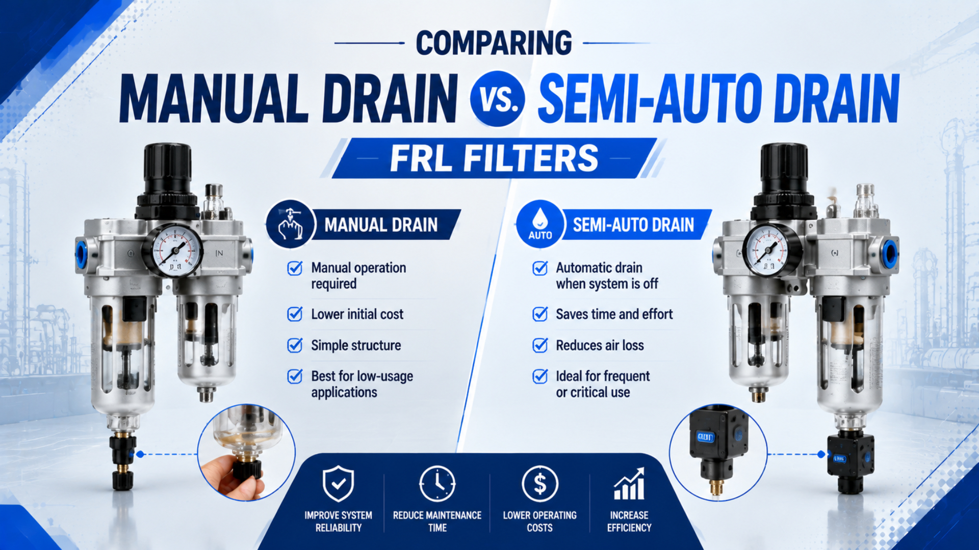
Choose a manual FRL drain when a trained person can inspect and empty the bowl before its usable capacity is reached. A semi-automatic normally open drain fits a system that regularly depressurizes, provided the selected model covers the actual pressure range; for a line that stays pressurized, assess a level-operated or electronic automatic drain instead.
Labels can conceal different trigger events. Manufacturers use separate terms for manual, semi-automatic, fully automatic float and electrically controlled drains, so selection must account for the opening event, condensate accumulation and the consequences of a mechanism that sticks open or closed.
Key Takeaways
- Festo defines four operating variants.
- A common semi-auto drain opens when compressed air is shut off.
- Continuous pressure can prevent drainage.
- Measure usable bowl volume and condensate rate before setting an inspection interval.
- Drain type alone cannot prove particles, water and oil meet the required ISO 8573 classes at the specified measurement point.
What Does Semi-Automatic Mean in an FRL Filter?
Festo identifies four condensate-drain variants: manual; semi-automatic normally open; fully automatic normally open; and fully automatic normally closed. In its terminology, the semi-automatic version opens when compressed air is shut off, while the fully automatic versions add level-dependent operation (Festo, accessed 2026).
That distinction corrects a common purchasing error. A semi-auto drain is not automatically a float drain. It may also be unable to discharge liquid while the FRL remains continuously pressurized. Some catalogs call the same general mechanism an overnight drain or pressure-release drain. Manual drains need deliberate actuation through a screw, pushbutton or valve. Some models permit operation under pressure; others require isolation and depressurization. Fully automatic drains form another group. A float device responds to liquid level. Electronic designs can add a test function plus an alarm output and controlled discharge valve, giving a control system more information than a purely mechanical device. Timed drains respond to a schedule rather than the amount of liquid present. A setting that works in one season can waste air or miss condensate in another.
The useful comparison isn’t “human versus automatic”; it is event-based versus condition-based drainage. Manual drainage depends on a maintenance event, a common semi-auto design waits for pressure release, and a float or level-sensing drain waits for liquid to reach a defined condition.
Four Drain Mechanisms, One Selection Problem
Parker’s compressed-air filter catalog distinguishes three mechanisms: a semi-automatic overnight drain; an automatic pulse drain; and an automatic float drain. The overnight type responds when system pressure is shut off. The float type instead responds to liquid level (Parker, accessed 2026).
Start with the trigger.
Use the following table to define the mechanism before comparing price or maintenance effort:
| Drain type | What initiates discharge? | Suitable starting point | Main verification |
|---|---|---|---|
| Manual | A person operates the drain | Attended equipment with a documented inspection route | Safe access, usable bowl volume, maximum interval |
| Semi-auto, normally open | System pressure falls to the model’s release condition | Equipment that reliably depressurizes before the bowl fills | Closing pressure, shutdown frequency, residual pressure |
| Fully automatic float | Liquid reaches a set level | Variable accumulation or systems that remain pressurized | Minimum pressure/flow, orientation, contaminant tolerance |
| Electronic level-sensing | A sensor detects liquid | Critical or remote service needing alarms or controlled discharge | Power, alarm logic, test method, valve fail state |
| Timed electric | A timer commands the valve | Stable, characterized condensate loads | Interval, open time, air loss, seasonal variation |
Timed operation isn’t automatically the best answer for a continuous-pressure line because a basic timer has no direct knowledge of liquid level. Where compressed-air loss matters, a zero-loss level drain can be a better fit. Float drainage may be simpler when electrical power and alarm integration aren’t required. Before deciding, record the exact manufacturer code: two assemblies with similar external threads can differ in sealing pressure, materials, approved orientation and bowl interface.
How Does Pressure State Change the Choice?
One Festo automatic drain model empties after pressure falls below 50 kPa and needs about 150 kPa plus 125 l/min of flow to close. Those model-specific figures show why universal pressure thresholds are unsafe and cannot be transferred to every semi-auto drain (Festo, 2024).
Pressure state decides this branch.
Map the real pressure cycle at the FRL, not just the machine schedule. A plant can stop production while leaving the branch pressurized. A machine isolation valve may vent downstream components but trap pressure inside the filter bowl. Conversely, a point-of-use filter may lose pressure several times per shift even though the main header stays charged. Does a three-shift machine automatically need a semi-auto drain? No. If it never depressurizes, a normally open design may never receive its discharge event. A continuously pressurized system needs a mechanism that removes condensate under its real operating conditions.
Check four states:
- Normal operation: Record bowl pressure.
- Planned shutdown: Verify whether the filter bowl actually reaches the drain’s opening condition.
- Abnormal stop: Determine whether an emergency stop vents or isolates the FRL, or whether it traps bowl pressure.
- Restart: Confirm closure without sustained air leakage, then verify that the available restart flow reaches the minimum required by the exact drain design.
How Much Condensate Can the Bowl Hold Between Drain Events?
Festo’s four drain variants are selected by operating behavior, not by one universal condensate rate. Actual liquid collection changes with inlet temperature, humidity and seasonal conditions; compressor aftercooling, dryers, receiver drainage, system pressure and airflow also affect what reaches the FRL (Festo, accessed 2026).
Capacity is only a clock.
Measure the collected volume at the FRL during a representative high-load period. Use the bowl manufacturer’s maximum permissible condensate level, not total geometric bowl volume. Then calculate the longest theoretical interval before that usable volume is reached:
Here, is the maximum theoretical interval in hours. The variable is the allowable condensate volume in millilitres between the empty condition and the manufacturer’s maximum level. The measured collection rate in millilitres per hour is .
Suppose a bowl has 90 ml of usable volume and a representative test collects 6 ml per hour. The theoretical interval is 15 hours, but that isn’t the service interval. Treat it as a ceiling. Choose a shorter documented interval that covers measurement uncertainty, higher seasonal humidity, a missed round and the consequence of carryover. Repeat the measurement after changes to compressor operation, dryer settings, production flow, ambient conditions or upstream drainage. When the rate varies widely, a level-operated drain can remove the scheduling guesswork; inspection for blockage, leakage and correct operation is still necessary.
Bowl capacity is a time buffer, not a drainage strategy. The same 90 ml usable volume may be adequate for an attended test stand and inadequate for an unattended process because the required detection and response times differ.
When Is a Manual Drain the Better Choice?
Festo defines manual drainage as one of four available condensate-drain variants rather than an obsolete or universally inferior option. It is sound when safe access and documented inspections are paired with measured accumulation that keeps the bowl below its permitted limit between reliable service events (Festo, accessed 2026).
Simplicity is the benefit.
Manual drainage is often easier to verify because there is no float or pilot mechanism waiting for a particular pressure condition. That simplicity can suit a laboratory bench, maintenance outlet, intermittently used machine or attended workshop station where the inspection responsibility is explicit.
Use a manual drain only when all of these conditions are satisfied:
- Safe access is available.
- The bowl and drain can be reached without entering a hazard zone or defeating a guard.
- Product instructions state whether pressure must be isolated and released before actuation.
- A named role owns the inspection; completed checks are recorded in the maintenance system.
- Measured condensate accumulation remains comfortably below usable capacity between the longest credible pair of checks.
- The process can tolerate the planned service stop, and a missed inspection is detectable before liquid reaches the downstream air path.
Manual drainage becomes weak when the procedure depends on memory alone. A label beside the bowl isn’t a control measure unless someone owns the check and the interval is supported by observed accumulation. For broader filter selection, compare particle and liquid-water duties with aerosol removal in the guide to water separators versus coalescing filters. Drain choice cannot correct a filter element selected for the wrong contaminant.
Where Does a Semi-Automatic Drain Fail the Application?
Festo’s semi-automatic normally open design uses one defined event: it opens when compressed air is shut off. If that event does not occur before the bowl reaches its allowable liquid level, the mechanism cannot provide the intended protection regardless of shift count or operator presence (Festo, accessed 2026).
Test both failure directions.
The first failure mode is no true depressurization. Residual pressure from a check valve or trapped line may keep the drain closed. A slow exhaust path or upstream isolation arrangement can do the same. The second is insufficient capacity between events. A machine that vents once per day can still overfill when condensate reaches the limit in six hours. The third is stuck open or leaking. Dirt on a valve seat can create continuous air loss, as can damage or an incompatible replacement part. Confirm that the valve reseats after pressurization. The fourth is stuck closed or blocked discharge. Ice and contamination are possible causes. So are a pinched tube, discharge back pressure and poor orientation. Route the outlet so discharge can be observed without creating a personnel hazard.
Drain Type Is Not ISO 8573 Compliance
ISO 8573-1 classifies compressed-air purity for three principal contaminants: particles; water; and oil. The class applies at the location where air is specified or measured, so it neither certifies a particular FRL drain nor states that one drain style creates the required purity (ISO, 2010).
A drain cannot dry air.
An FRL filter can separate particles and collected liquid according to its design. Its drain removes that captured liquid. Neither function alone controls all water vapor in the air. When the required water class is expressed by pressure dew point, the treatment train may need an aftercooler and receiver drainage. It may also require a refrigerated or adsorption dryer plus suitable filters. Distribution must prevent recondensation. This is why a semi-auto drain cannot “ensure ISO 8573 compliance.” It can reduce the chance that collected liquid remains in the bowl. Compliance still depends on the specified class and measurement point, as well as operating pressure and sampling method. The complete treatment system and its verification records remain part of the claim.
Use the guide to ISO compressed-air quality standards to define the required contaminant classes. Then check pressure dew point separately from bulk-liquid drainage. A drain is a removal endpoint, not a purity generator. If liquid reaches the FRL faster than the drain can remove it, fix the drainage problem. When water vapor condenses downstream, investigate dew point and pipe temperature rather than expecting a different bowl drain to change the air class.
Retrofit, Commissioning, and Maintenance Checks
One Festo electric condensate-drain specification requires vertical mounting within ±5° and lists an operating-pressure range of 0.8 to 16 bar. These model-specific limits show why thread fit alone cannot establish replacement compatibility. The selected assembly must satisfy its complete datasheet (Festo, 2026).
Thread fit proves very little.
Before retrofitting a drain or complete bowl assembly, compare:
- Record the exact FRL series.
- The complete manufacturer and size designation, including any suffix that changes the bowl or drain option.
- Bowl connection and sealing geometry rather than nominal port size alone.
- Permitted bowl material, guard, temperature and fluid compatibility across the intended pressure range.
- Drain orientation plus closing pressure, discharge-port limits and allowable outlet back pressure.
- For an electric drain, document supply voltage, alarm contact, ingress protection, manual override, approved cable entry, replacement instructions and the specified tightening method.
Commission the assembly in both directions and confirm the intended discharge before checking closure without sustained leakage. Test at minimum operating pressure, normal pressure, shutdown and restart. Introduce test liquid only by a method permitted in the product instructions. During the first representative operating period, inspect the visible level and stop if the bowl approaches its maximum. Review measured accumulation plus upstream separation and drainage. Continuous venting also requires isolation and inspection of the seat, contamination, pressure conditions and part compatibility. ISO 4414 addresses significant pneumatic hazards within installation, adjustment and maintenance; it also covers reliable operation and energy efficiency (ISO, 2010). Apply the machine risk assessment and lockout procedure before opening a pressurized bowl or drain path.
For the wider service-unit context, see why the FRL affects pneumatic-system reliability and the guide to air-source treatment units.
Manual vs. Semi-Auto Drain FRL FAQs
Festo’s four drain variants cover manual; semi-automatic normally open; fully automatic normally open; and fully automatic normally closed operation. The five questions below address the main verification boundaries. These are pressure state and capacity, compatibility and continuous operation, plus air-quality claims (Festo, accessed 2026).
Will a semi-auto FRL drain work on a system that stays pressurized?
Not when the selected drain relies on system shutdown but the bowl never reaches its release condition. Measure residual pressure at the bowl during normal stops, then select a manufacturer-approved float, level-sensing or other automatic design only if it can discharge under the actual pressure and flow conditions.
How do I set a safe manual-drain interval?
Measure the collected volume during a representative high-condensate period. Divide the manufacturer’s usable bowl capacity by that hourly rate, then set a shorter documented interval that covers seasonal change, missed rounds, production variation and carryover risk; recheck after changes to the compressor, dryer, flow or piping.
Can I replace a manual drain with a semi-auto drain using the same bowl?
Only when the FRL manufacturer or qualified replacement supplier confirms the exact body and bowl, plus the seal and drain interface. Matching thread size is insufficient. Check pressure range and orientation. Material compatibility, temperature, discharge connection and bowl guard also matter. Follow the specified assembly instructions.
Does a semi-auto drain guarantee ISO 8573 water-class compliance?
No. ISO 8573-1 classifies water at the specified or measured location, while an FRL drain removes liquid already collected in the bowl. Pressure dew point depends on the complete treatment and distribution system. Verify the required class with an appropriate sampling and measurement plan.
How should I test the drain after installation?
Follow the product instructions and machine safety procedure. Verify the intended discharge event, complete liquid release, resealing at the lowest and normal operating pressures, blocked-discharge detection and continuous-leak response; record pressure, liquid level, orientation, test date and the person responsible for follow-up.