

Key Takeaways
- Galvanic corrosion needs four conditions: dissimilar conductive materials, electrical contact, a shared electrolyte, and enough electrochemical driving force.
- A white deposit, red stain, or pit is evidence of corrosion, not proof of its cause.
- Material state, exposed area ratio, joint sealing, drainage, and coating damage belong in every failure report.
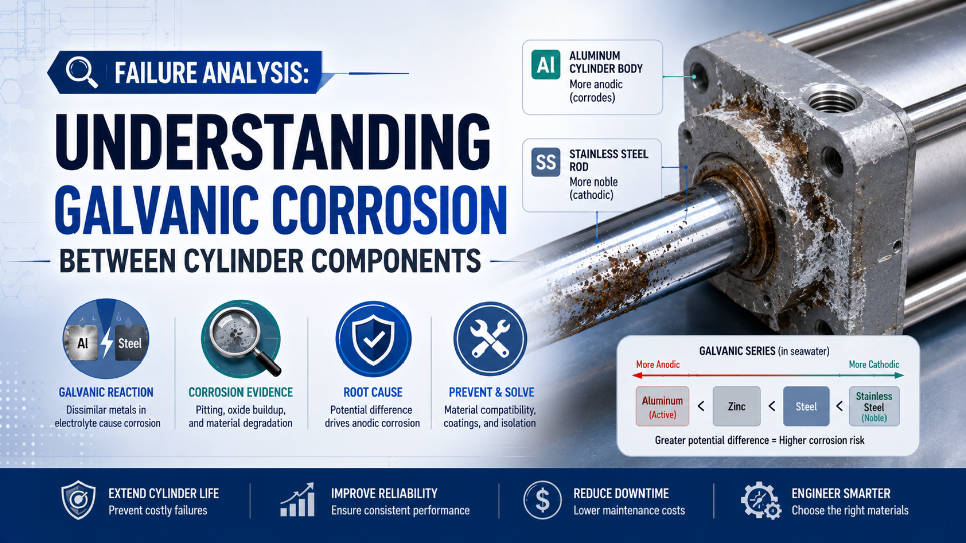
Galvanic corrosion between cylinder components is confirmed only when the damage pattern fits an electrically connected dissimilar-material couple exposed to the same conductive moisture. The anodic member corrodes faster than it would alone. The cathodic member corrodes more slowly. Remove one essential part of the cell to stop the mechanism. This behavior is defined by AMPP’s galvanic-corrosion overview, retrieved in 2026.
That definition matters in a pneumatic cylinder. An aluminum end cap may sit near several other materials without sharing a continuous electrical path or electrolyte. Examples include a stainless rod with plated hardware. Brass fittings or steel mounts can also be nearby. Conversely, damaged aluminum under a wet stainless fastener can become a concentrated anodic site.
The assembly details decide the risk.
What Conditions Turn a Mixed-Metal Cylinder Joint Into a Galvanic Cell?
ASTM G71-81(2024) defines galvanic testing around two dissimilar metals in electrical contact inside an electrolyte. A cylinder investigation can translate that boundary into four checks. Identify both conductive materials. Prove the electrical path. Identify the shared conductive liquid. Then establish a plausible potential difference under the service conditions.
All four conditions must overlap at the damaged joint:
- Different electrochemical behavior. Alloy designation and surface condition matter. “Aluminum” and “stainless” are too broad for a defensible report.
- Electrical continuity. Direct metal contact is common, but current may also pass through a fastener, bracket, bearing, conductive contamination, or another metallic path.
- A shared electrolyte. Wash water, condensate, salt solution, process chemicals, or contaminated cleaner can bridge both surfaces. Dry contact alone doesn’t complete the cell.
- A sustained reaction path. The materials and environment must support anodic dissolution together with the corresponding cathodic reaction.
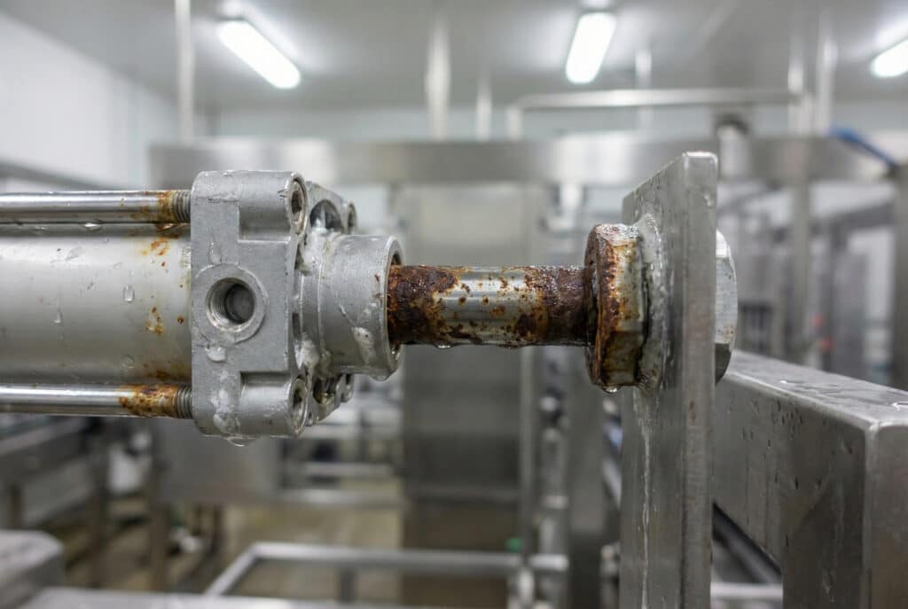 Surface deposits justify a closer inspection. Neither color nor location proves galvanic coupling by itself.
Start at the actual interface. A stainless piston rod normally moves through polymer seals and a bearing system. That construction does not automatically put bare steel in electrical contact with the aluminum tube or end cap. A stainless tie rod installed through a damaged finish creates a more credible couple. A bare fastener can do the same. Measure continuity on the cleaned assembly after de-energizing it. Do not infer continuity from a parts list.
The fastest useful failure tree starts with the current path rather than the galvanic series. A dissimilar-metal explanation is incomplete when no conductive route joins the suspected surfaces.
Then test the alternatives: chemical attack or crevice corrosion may fit the pattern. Coating failure and fretting remain open beside contaminated condensate or corrosion from a third component.
What Can the Damage Pattern Prove, and What Can It Only Suggest?
FAA AC 43-4A describes white-to-gray aluminum products and reddish-brown oxide on low-alloy steel. Stainless damage may instead appear as roughening or dark stains; these clues locate affected material without identifying the mechanism by themselves.
Use appearance as a screening tool:
| Observation | What it supports | What it does not prove |
|---|---|---|
| White or gray deposits on aluminum | Aluminum oxidation or hydroxide products are plausible | That a second metal caused the attack |
| Pitting concentrated beside a fastener | A local cell, coating break, or crevice is plausible | Which mechanism dominated |
| Red-brown residue | Steel or transferred iron contamination may be present | That the stainless part itself is failing |
| Blistered coating around a joint | Moisture has reached or formed beneath the coating | That the substrate loss is galvanic rather than filiform or underfilm corrosion |
| Damage repeated at one material boundary | The interface is relevant | That electrical continuity and shared electrolyte existed during service |
Diagnostic example: evidence that separates cause from appearance
Consider a washdown cylinder with deep pitting beneath one stainless mounting washer yet no comparable loss around the other mounting points. The location supports an interface-driven mechanism without proving galvanic corrosion, so the investigator documents the wetting direction and coating break before cleaning and then checks whether the washer remains electrically connected to the exposed aluminum during assembly. Cleaner records show whether one conductive liquid could reach both surfaces; an unaffected joint on the same machine provides a useful control under nearly the same operating history. If continuity is absent after the actual joint stack is reconstructed or the liquid could reach only one member, the report keeps crevice attack and chemical coating failure open instead of forcing a galvanic verdict from pit shape alone. This sequence preserves the distinction between evidence that identifies the damaged material and evidence that establishes the electrochemical cause.
Location changes the diagnosis.
Look at where metal was lost. In a galvanic couple, the anodic surface should show accelerated attack relative to a comparable uncoupled surface exposed to the same environment. The cathodic part can appear relatively intact. Deep local damage on a small anodic area next to a large cathodic surface is especially significant.
Don’t clean away all evidence before documenting it: photograph the assembly as received with its orientation and drainage direction. Record deposit color; preserve loose products for possible laboratory identification before exposing coating boundaries or pit geometry on the least intrusive path.
Why Can’t a Generic Galvanic Series Predict Cylinder Life?
ASTM G82-98(2021)e1 defines a galvanic series for the environment of interest and the relevant active or passive alloy states. A seawater ranking can guide a wet chloride review; it cannot assign one failure rate to washdown equipment or chemical service or dry indoor conditions.
A galvanic series ranks observed corrosion potentials rather than service life; its order responds to electrolyte chemistry together with temperature and oxygen availability. Deposits or surface films can alter the local alloy state, so passive stainless steel in a seawater table may not behave like stainless steel that loses passivity elsewhere.
Potential separation is only one input. Conductivity controls how readily ionic current passes through the liquid. Wet duration controls reaction time. A chloride-bearing wash can both increase conductivity and disrupt protective films. Cleaner residues trapped behind a mount can keep the interface wet long after the visible machine surface dries.
This is why “aluminum plus stainless equals high risk” is not a complete finding. A proper statement identifies the exact alloys plus finishes. It names the electrolyte and exposure cycle. It records temperature range plus joint geometry. Continuity evidence completes the statement. For washdown equipment, compare those conditions with the selection boundaries in our stainless steel cylinder guide. Marine installations also need the chloride and drainage checks covered in the marine cylinder selection guide.
Cathode-to-Anode Area Ratio and the Failure Pattern
AMPP warns against a small anode coupled to a large cathode because current becomes concentrated on the anodic area. NASA-STD-6012A therefore requires representative test electrode areas; a small coating defect beside a large cathode can lose thickness quickly despite modest total current.
Define the exposed cathode-to-anode area ratio as:
Here, represents wetted cathodic area while represents wetted anodic area in the same electrolyte. Their dimensionless ratio describes geometry; it does not calculate corrosion rate.
If the total galvanic current is , the average current density on the exposed anode is:
Current density is expressed in amperes per square metre when uses amperes and uses square metres. Predicting metal loss also requires exposure time and electrochemical efficiency; alloy behavior together with polarization and the real current distribution remain essential.
Area-ratio example: why total component size can mislead
Suppose a broad stainless bracket remains wet while only a narrow scratch exposes aluminum beneath its edge. Using the complete aluminum end-cap surface as would hide the geometry at the active defect, because most of that surface is electrically insulated from the electrolyte by intact finish; the useful denominator is the aluminum area that is both exposed and wetted in the coupled region. The same care applies to : a stainless rod sealed inside the bearing system does not enlarge the active cathode merely because it appears on the bill of materials. Even after the areas are mapped, expresses geometry rather than time to failure, so any quantitative metal-loss estimate still needs measured or validated current behavior with representative chemistry and exposure duration. This keeps the analysis focused on surfaces that could actually exchange current during the documented exposure.
Geometry changes severity.
Coating only the anodic member can create a severe local geometry after a scratch: most of the anode remains insulated while a small exposed defect stays coupled to a much larger cathode. The plan must therefore cover edges plus fastener holes as well as damage plus drainage paths; inspection access plus repair intervals belong in the same system.
Cylinder Failure-Analysis Workflow
ASTM G71-81(2024) covers materials plus specimen preparation as well as the environment plus result evaluation. Plant investigators should preserve those controls through as-found records plus unaffected comparisons before any laboratory escalation.
1. Make the machine safe and preserve evidence
Follow the machine’s lockout procedure: isolate energy, exhaust stored pressure, and secure any gravity load. Photograph the cylinder before loosening hardware. Include its orientation with spray sources as well as hidden bracket surfaces plus drain paths.
2. Reconstruct the exposure
Start with the cleaner’s product name, working concentration, and temperature; document rinse practice and water quality as separate conditions. Add salt exposure with humidity and drying time. Compare safety data with maintenance records to distinguish a single spill from a repeated washdown film.
3. Identify the materials and surface states
Use drawings, supplier certificates, and part markings to establish the material system; review the coating specification rather than relying on color. Confirm uncertain alloys appropriately. Record surface treatments with passivation plus repairs while separating welds or bare edges from deposited iron contamination.
4. Map continuity and wetted geometry
After safe disassembly clean only contact points needed for continuity while preserving finishes plus insulators in place. Measure resistance across the suspected members; map the likely wet path plus only its electrolyte-exposed electrode areas because a fully enclosed stainless rod is not part of the wetted cathode.
5. Measure damage and compare controls
Measure maximum pit depth, section loss, coating undercut, and seal damage; record fastener condition and leakage separately. Compare metal away from the joint or use an identical cylinder from a drier location; involve a qualified laboratory when safety or fleet replacement requires metallography with deposit analysis or controlled testing.
In our experience, a weak report begins with deposit color before jumping to a material verdict. A stronger report places the current path plus wet path on one marked assembly drawing.
That drawing changes the discussion by locating the next action at the material interface or joint seal. Sometimes drainage is the real control; in other cases cleaner management or a mechanical fault deserves priority.
Which Prevention Strategy Fits the Verified Failure Path?
MIL-STD-889C lists four routes: compatible materials, liquid exclusion, sealed surfaces, and inert barriers where continuity is unnecessary. It also warns against a small anode coupled to a larger cathode; cylinder redesign should break the failure path found during inspection.
| Verified weakness | Preferred design response | Verification evidence |
|---|---|---|
| Direct metal contact is unnecessary | Add an inert, non-absorbing insulating washer, sleeve, gasket, or barrier | No continuity across the protected joint after assembly |
| Wash liquid reaches the interface | Seal faying surfaces and external edges; preserve drainage | Wetting test shows no trapped liquid or blocked drain path |
| Exposed alloys are incompatible in service electrolyte | Select a closer material combination or isolate the couple | Assembly-level compatibility review under representative exposure |
| Coating damage creates a small anode | Protect the joint system, edges, holes, and fasteners; define repair limits | Coating inspection plus controlled defect or service-simulation test |
| Cleaner residue raises conductivity or attacks films | Correct concentration, rinse, material compatibility, and drying | Documented chemistry plus residue and rinse checks |
| Existing geometry cannot be kept dry or inspected | Use a cylinder designed for the environment or relocate/shield it | Model-specific environmental and chemical compatibility evidence |
Avoid absorbing separators because a gasket that wicks cleaner can hold electrolyte against the protected joint. Any insulator needs suitable compressive strength with temperature and chemical resistance; the revised joint must preserve alignment and grounding within the manufacturer’s assembly requirements.
Treat every finish as a system rather than a generic quality label. Specify substrate preparation first. Name the coating type plus its relevant thickness. Define edge treatment and cure. Add the compatible cleaner range. The specification also needs an inspection method plus repair procedure. Where electrical bonding is required, resolve that requirement with corrosion protection at the same design review.
Sacrificial anodes are a valid cathodic-protection principle rather than a default pneumatic-cylinder accessory. A designed system must establish connection, electrolyte exposure, and current demand; most external joints have more direct controls through compatible materials or isolation together with sealing and drainage or a maintainable coating.
Repair, Replace, or Redesign the Cylinder Assembly?
FAA AC 43-4A starts with visual examination before identifying penetrant, magnetic-particle, eddy-current, or ultrasonic methods for suitable materials and flaw locations. Radiography and acoustic emission have different boundaries; select from the suspected defect and consequence because surface cleaning cannot repair structural loss or sealing damage.
Repair may be reasonable only for superficial corrosion within manufacturer limits when load-bearing surfaces and seal tracks remain unaffected. The coating needs an approved repair process with a correctable exposure source; record removed material and restored protection without polishing rod pits before confirming permissible dimensions and finish.
Replacement is the safe default when the manufacturer provides no repair limit. Replace affected parts when pit depth or section loss exceeds tolerance. Damaged threads and fastener seats also disqualify a simple cosmetic repair. The same is true for damage on a rod or seal track. Suspected cracks require an appropriate inspection decision. Pressure containment must remain demonstrable. For internal surface damage compare the symptoms with the barrel scoring and piston-damage guide before assigning corrosion as the only cause.
Redesign the assembly when replacement leaves the same wet conductive joint in place; pooled water or aggressive cleaner or stainless hardware on exposed aluminum can repeat the failure. Review the actuator with its brackets, fittings, guards, and wash direction. Use the corrosion-resistant fittings guide to extend the review beyond the actuator.
What Should the Final Failure Report Conclude?
NASA-STD-6012A requires assembly-level evaluation of incompatible dissimilar-metal systems while treating its seawater compatibility table as guidance. Plant reports should use the same discipline: separate observations from measurements and name excluded alternatives before showing how the proposed control breaks the verified cell.
A useful conclusion contains six items:
- Failure location and extent: material lost, maximum depth, affected interfaces, and functional consequences.
- Material system: exact alloys, finishes, fasteners, repairs, and relevant surface condition.
- Electrical path: measured or physically demonstrated connection between the suspected couple.
- Electrolyte path: liquid identity, entry route, wet duration, deposits, and drainage condition.
- Mechanism decision: evidence supporting galvanic corrosion and evidence against plausible alternatives.
- Corrective action and verification: repair or replacement limit, design change, exposure control, inspection interval, and acceptance evidence.
Use calibrated language. “Confirmed galvanic corrosion” needs the complete chain. “Consistent with galvanic corrosion” fits a case with a matching damage pattern but incomplete evidence. The missing evidence might concern current path or electrolyte. It might instead concern the material state. “Dissimilar metals present” is only an observation.
The final action should remove or control a necessary cell component: compatible materials reduce the driving condition while isolation breaks the current path. Sealing or drainage removes the electrolyte; improved area geometry reduces concentration while a qualified protective system preserves the interface.
Galvanic Corrosion Between Cylinder Components FAQs
ASTM G71-81(2024) treats galvanic behavior as a coupled-material test in a defined electrolyte. ASTM G82-98(2021)e1 requires an environment-specific series; together they rule out universal life claims or a generic ranking without service plus assembly evidence.
Can galvanic corrosion occur if the two metals do not touch directly?
Yes. Direct contact is common, but a fastener, bracket, bearing, or machine frame can also complete the electrical path. Both materials must still contact the same electrolyte. Without an electrical connection or a shared wet path, proximity alone does not establish a galvanic couple.
Is stainless steel always the cathode in a cylinder joint?
No. Exact alloy and surface state determine whether stainless behaves cathodically or anodically. Temperature and deposits can change that behavior. Passive stainless steel is relatively noble in seawater tables, but the label alone cannot assign the anode and cathode for another environment.
Does anodizing an aluminum cylinder eliminate galvanic corrosion risk?
No. Anodizing can add electrical resistance to the aluminum surface. Holes or cut edges can expose the substrate just as scratches or threaded features can. A small wet defect beside a large cathode can concentrate attack, so review the complete joint finish before setting inspection and repair limits.
Can a voltage reading alone confirm galvanic corrosion?
No. A potential difference supports screening. Electrolyte chemistry and surface state affect the response while area ratio changes local current density and wet duration changes exposure. ASTM G71 therefore uses controlled coupled testing. Combine the reading with confirmed materials, damage mapping, service chemistry, and a shared-electrolyte record.
Should a sacrificial anode be added to a corroding pneumatic cylinder?
Not as an improvised fix. A designed cathodic-protection system needs a controlled current path. The anode material, current capacity, placement, inspection access, and replacement plan all need engineering. Most external cylinder joints have more direct controls. Material compatibility or electrical isolation can break the couple; joint sealing with drainage can remove the electrolyte while cleaner control and maintainable coatings protect the interface.
Sources and technical references
- AMPP, “Galvanic Corrosion”. Used for galvanic-cell behavior, anode and cathode response, galvanic-series context, and exposed-area ratio. Retrieved 2026-07-23.
- ASTM International, “ASTM G71-81(2024), Standard Guide for Conducting and Evaluating Galvanic Corrosion Tests in Electrolytes”. Used for test scope, material preparation, defined electrolytes, exposure, and evaluation boundaries. Retrieved 2026-07-23.
- ASTM International, “ASTM G82-98(2021)e1, Standard Guide for Development and Use of a Galvanic Series for Predicting Galvanic Corrosion Performance”. Used for environment-specific galvanic-series interpretation and active/passive material states. Retrieved 2026-07-23.
- NASA, “NASA-STD-6012A: Corrosion Protection for Space Flight Hardware”, approved 2022-03-23. Used for exposed-area representation, dissimilar-metal guidance, and assembly-level verification principles. Retrieved 2026-07-23.
- U.S. Department of Defense, “MIL-STD-889C: Dissimilar Metals”, 2016. Used for isolation, electrolyte exclusion, joint sealing, coating maintenance, and area-ratio design guidance. Retrieved 2026-07-23.
- Federal Aviation Administration, “AC 43-4A: Corrosion Control for Aircraft”, 1991. Used for corrosion-product appearance, visual evidence limits, drainage, and inspection-method context. Retrieved 2026-07-23.