

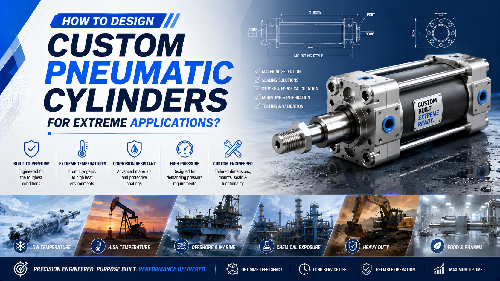
Custom pneumatic cylinder design begins by converting an extreme operating condition into measurable loads, temperatures, pressures, interfaces, and acceptance evidence. The finished actuator is limited by its complete load path and its lowest-rated component, not by the strongest seal material, thickest tube, largest rod, or most precise machining process considered in isolation.
The practical sequence is:
- prove that a catalog or configured cylinder cannot meet the duty;
- freeze the installed load, motion, environment, interfaces, and failure consequences;
- size the pressure boundary and mechanical load path;
- select compatible seals, lubricants, materials, finishes, sensors, and accessories;
- control functional dimensions and verification methods on the drawing;
- validate the released configuration against predefined criteria.
Key Takeaways
- “Extreme” is a condition outside the selected product’s documented capability, not a marketing label.
- Use dynamic pressure at the cylinder, not an unloaded regulator setting, for force review.
- Treat seal compound, profile, lubricant, counterface, clearance, pressure, speed, and temperature as one tribological system.
- Separate axial rod buckling, lateral deflection, guide moments, thermal growth, and mounting alignment.
- A successful pressure or leakage check does not prove environmental life, guide capacity, cushion energy, or installed-machine safety.
What Makes a Pneumatic Cylinder a True Custom Design?
ISO 15552 covers detachable-mount pneumatic cylinders with 32 to 320 mm bores in a 1,000 kPa (10 bar) series, but it standardizes interchangeability dimensions rather than every application limit (ISO 15552, confirmed 2025). A true custom design is justified only when a controlled catalog option cannot satisfy a required function or interface.
Use three levels before releasing new geometry:
| Solution level | What changes | Appropriate evidence |
|---|---|---|
| Standard catalog cylinder | Only the published bore, stroke, mounting, port, cushion, sensor, and seal options | Exact model code, current datasheet, sizing record |
| Configured or modified standard | A controlled rod end, port position, stroke, seal option, scraper, lubricant, sensor, or mounting detail | Supplier-approved option drawing and revised limits |
| True custom cylinder | Pressure boundary, body, rod, guide, end cap, material system, sensing, or acceptance method leaves the established platform | Controlled requirements, calculations, drawing, risk review, test plan, released bill of materials |
Do not choose a true custom design merely because one catalog dimension is inconvenient. A mounting adapter, external guide, heat shield, remote valve, floating joint, or different actuator architecture may solve the problem with less validation burden. Conversely, a standard-looking cylinder is still a special application if its actual temperature, chemistry, duty, side load, or failure consequence falls outside the selected series documentation.
The companion guide on standard versus custom pneumatic cylinders covers the commercial and platform decision. Once a true custom design is justified, the engineering work starts with the application boundary below.
Which Inputs Must Be Frozen Before Cylinder Design Starts?
Festo’s pneumatic sizing workflow starts with three main inputs: positioning time, mass, and stroke, which generate a pneumatic motion chain (Festo, retrieved 2026). An extreme-duty specification must add pressure, load direction, duty, environment, interfaces, safety, and verification before any material or seal is selected.
Freeze the worst credible operating cases, not only the normal cycle:
| Requirement group | Minimum design inputs | Evidence needed at release |
|---|---|---|
| Motion | Working stroke, permitted overtravel, extend/retract time, dwell, cycle rate, position requirements | Sequence chart and timing tolerance |
| Load | Moving mass, process force, gravity, acceleration, friction, center-of-gravity offsets, jam or stop case | Load-case table and dimensioned load-path sketch |
| Air supply | Minimum dynamic pressure, maximum available pressure, air quality, lubricant policy, valve and tube restrictions | Pressure measurement location and circuit |
| Structure | Orientation, mounting style, bracket stiffness, guide arrangement, rod-end geometry, external stops | Interface drawing and reaction-force model |
| Environment | Body temperature, radiant heat, cold startup, dust, water, chemicals, washdown, corrosion, UV, vibration | Measured exposure profile and material-compatibility requirements |
| Interfaces | Envelope, datums, ports, fittings, sensors, cables, guards, service access | Interface-control drawing |
| Safety | Stored energy, vertical load, loss of air or power, unexpected restart, exhaust hazards, maintenance access | Machine risk assessment and required safety functions |
| Acceptance | Dimensions, leakage, function, pressure, temperature, speed, load, cycle profile, documents | Agreed test matrix with instruments and pass/fail limits |
ISO 4414 applies pneumatic safety principles across design, construction, modification, installation, operation, maintenance, and cleaning, not only to the component on the bench (ISO 4414). That means the cylinder specification must include foreseeable fault and service states. A vertical axis, for example, needs a defined safe response to lost pressure; a large bore exhausting near personnel needs a controlled exhaust path.
How Should Pressure and Load Capacity Be Engineered?
ISO 15552’s 10 bar series is a dimensional standard, not permission to assign 10 bar or any higher value to an unverified custom pressure boundary (ISO 15552). Working, maximum, proof, and failure pressures must come from the released geometry, material condition, joining method, applicable requirements, and agreed verification plan.
Start by separating actuator thrust from structural capacity. For a single-rod cylinder extending, a useful first-pass force balance is:
where:
- is cap-end gauge pressure measured during motion;
- is rod-end gauge backpressure during the same event;
- is full piston area;
- is the rod-side annular area;
- represents seal, bearing, and guide friction.
Compare with the required load for each position and direction. Do not replace the two measured chamber pressures with one regulator value when tubing, valves, speed controls, silencers, and flow demand create dynamic loss or exhaust backpressure. The Pneumatic Cylinder Force Calculator is useful for initial bore screening, but the released design still needs the real circuit pressures.
Then trace the same load through every structural interface:
- piston and rod connection;
- rod thread, wrench flat, shoulder, and attachment;
- barrel, end caps, tie rods, retaining features, or profile connections;
- bearings, wear rings, guides, and mounting brackets;
- machine frame, hard stops, and payload connection.
Check axial thrust, transverse force, bending moment, torque, impact, pressure thrust on end closures, thermal preload, and credible jam loads separately. A larger piston rod may improve column stability while increasing retract-side area loss and moving mass. A thicker barrel may improve one stress result while leaving the end connection, port boss, fastener, or mounting bracket as the governing feature.
How Do Seals, Lubricants, and Materials Work as One System?
Parker lists approximate basic-polymer ranges such as −34°C to 121°C for general-service NBR and −26°C to 205°C for fluorocarbon, while warning that the usable range can change significantly with the medium and that actual service testing is required (Parker O-Ring Handbook). Polymer-family labels therefore cannot rate a cylinder assembly.
Define every sealing position by function:
| Position | Main job | Typical design questions |
|---|---|---|
| Piston seal | Separate working chambers during motion and dwell | Leakage limit, pressure reversal, speed, breakaway, bore finish, wear |
| Rod seal | Retain pressure on a moving rod | Rod finish, lubrication, side load, extrusion clearance, temperature |
| Wiper or scraper | Limit ingress from the exposed rod | Particle size, mud or ice, chemical exposure, rod-coating compatibility |
| Static seal | Seal end-cap, port, sensor, or plug interfaces | Compression set, thermal cycling, medium, assembly damage |
| Bearing or wear ring | Control contact and guide the piston or rod | Side load, clearance, temperature growth, creep, debris embedding |
PTFE, filled PTFE, PEEK, FKM, FFKM, polyurethane, silicone, and engineering composites describe material families, not interchangeable solutions. A harder material may require an energizer or tighter surface control. A high-temperature compound may have poor cold-start flexibility. A chemically resistant seal may still fail through abrasion, inadequate lubrication, wrong extrusion clearance, or installation damage.
Select the counterfaces at the same time. Rod coating, bore finish, hardness, waviness, lead, defects, and corrosion behavior affect the sealing pair. Where corrosion is important, define the actual electrolyte and exposure cycle. ISO 9227 salt-spray tests can detect coating discontinuities, but they are not intended to rank materials for service or predict long-term corrosion resistance (ISO 9227, 2022).
Compressed air is also part of the material system. ISO 8573-1 classifies air purity in three primary contaminant groups: particles, water, and oil (ISO 8573-1). State the required class and measurement location. Cold service makes water and dew point critical; hot service can accelerate grease oxidation; dry air and high cycling can change the lubricant film at dynamic seals.
For a dedicated heat review, use the high-temperature pneumatic cylinder guide. The custom design should inherit its measured-temperature and whole-assembly logic rather than repeat a generic seal temperature chart.
How Should Long Strokes and Special Guides Be Designed?
Parker publishes OSP-P rodless-cylinder configurations with standard stroke selection up to 6,000 mm and engineered long-stroke versions beyond that range, demonstrating that usable travel is product- and support-specific (Parker OSP-P). A custom long-stroke actuator must separate rod buckling, lateral deflection, guide loading, profile support, airflow, stopping, and alignment.
A piston rod pushing in compression can be screened as a column:
For a solid circular rod:
Here, is ideal Euler critical load, is elastic modulus, is second moment of area, is the effective-length factor, is unsupported length, and is rod diameter. This screen assumes a straight, elastic, concentrically loaded column with defined end conditions. Real cylinder selection must also use the manufacturer’s mounting and stroke limits, safety method, rod extensions, threads, joints, and load eccentricity.
Lateral deflection is a different problem. Its equation depends on whether the rod or guide behaves as a cantilever, simply supported beam, guided member, or multi-support structure, and whether the load is concentrated or distributed. Do not apply the cantilever expression unless that boundary and load actually describe the part.
Thermal growth requires another independent check:
is length change, is the material’s coefficient of thermal expansion, is the reference length, and is temperature change. For dissimilar guide, frame, rod, and profile materials, compare their individual growth instead of assuming one universal millimetre-per-metre value. Floating connections or one controlled expansion direction can prevent thermal growth from becoming side load.
The long-stroke pneumatic cylinder guide covers architecture, airflow, and stopping in more depth. If impact energy governs the design, use the Cylinder Cushion Energy Calculator and then apply the selected product’s catalog method.
Which Manufacturing Details Belong on the Drawing?
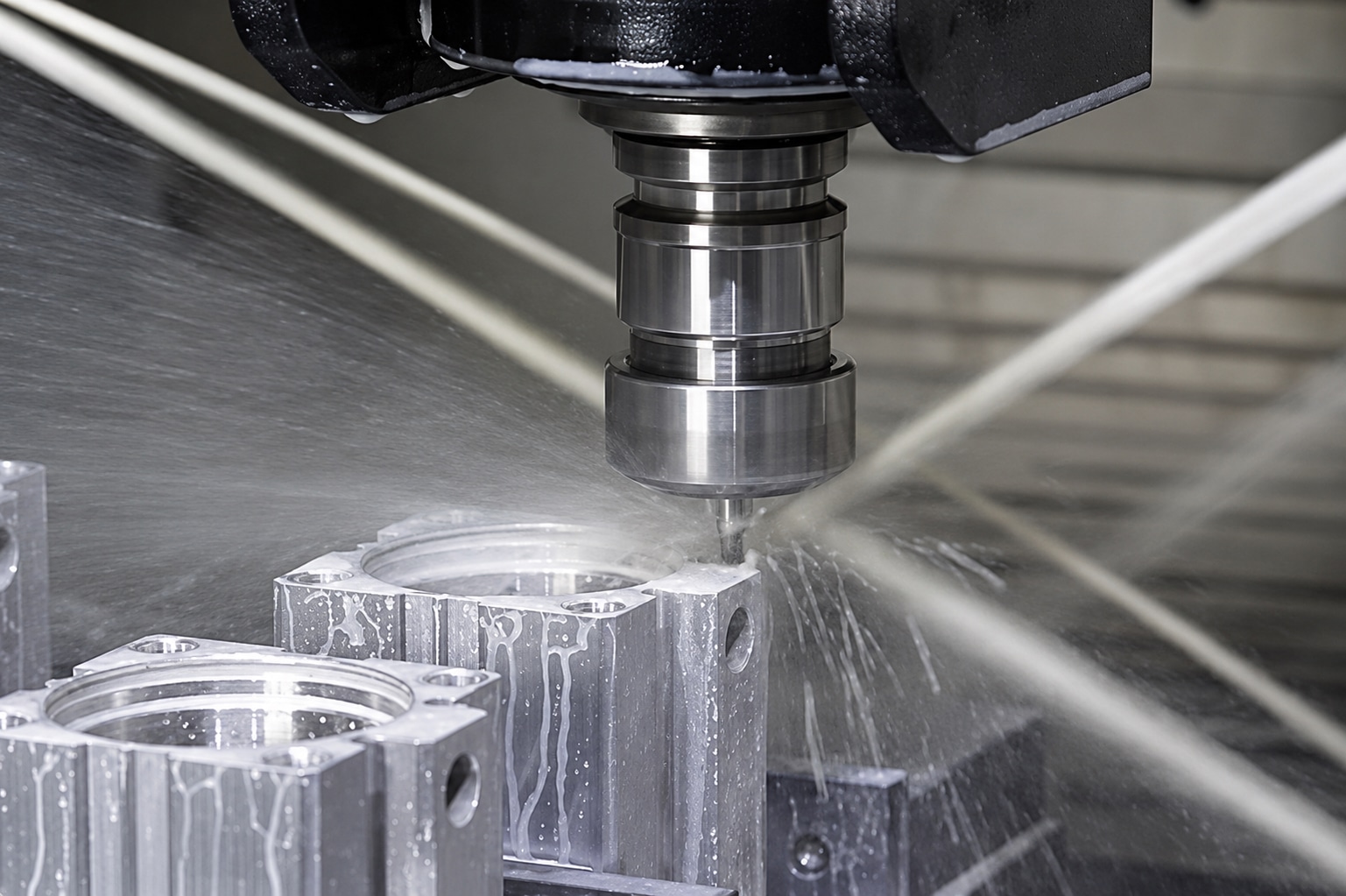
ISO 10099 defines final examination and acceptance criteria for one specific family: double-acting, single-rod pneumatic cylinders (ISO 10099, confirmed 2023). It does not turn “5-axis CNC,” “wire EDM,” “precision grinding,” or “heat treatment” into a universal tolerance. The drawing must control the functional result and its measurement method.
Define only tolerances that protect a known function:
| Functional requirement | Drawing and inspection content |
|---|---|
| Seal motion | Finished diameter, surface texture parameter and cutoff, lead or waviness requirement where relevant, allowable defects |
| Bearing alignment | Datum system, bore-to-rod coaxiality or runout control, measurement setup, assembly condition |
| Guide motion | Rail datums, straightness, parallelism, preload or clearance, load direction, measurement length and temperature |
| Pressure boundary | Material and condition, minimum wall or ligament, thread and port details, joining method, inspection and pressure-test requirement |
| Thermal assembly | Reference temperature, operating clearances, material pair, controlled expansion direction |
| Coated surface | Substrate preparation, finished dimension, coating process and thickness where functional, post-finish, masking, defect and adhesion criteria |
| Service interface | Port orientation, mounting datums, rod-end thread, sensor location, connector clearance, tool and seal access |
Choose the manufacturing route after the functional requirements are known. Wire EDM may suit conductive hardened materials or internal profiles; grinding may control a finished bearing surface; heat treatment may improve wear or strength but can distort the part; coating adds thickness and may change edge condition or fatigue behavior. The process sequence must leave enough stock and access for final control.
In our experience reviewing custom-cylinder drawings, one question exposes unnecessary precision quickly: “What failure does this tolerance prevent, and how will production verify it?” If no one can answer both parts, the tolerance may add cost without controlling the actuator.
How Should the Prototype and Finished Cylinder Be Validated?
ISO 19973-3 reports pneumatic piston-rod cylinder life using two service measures: cycles or kilometres, under defined test conditions and thresholds (ISO 19973-3). ISO/TR 16194 supplies accelerated-life guidance but no universal acceleration procedure, so increasing pressure or cycling rate does not automatically reproduce the intended failure mode (ISO/TR 16194).
Separate four evidence levels:
- Analysis evidence: load cases, force and buckling screens, stress or deflection analysis, tolerance stack, thermal-growth review, material compatibility and risk assessment.
- Manufacturing evidence: material identity where required, critical dimensions, surface measurements, coating or heat-treatment records, assembly controls and nonconformance disposition.
- Component acceptance: visual examination, full-stroke function, internal and external leakage, minimum operating behavior, pressure test, sensors and cushions under the agreed configuration.
- Application qualification: representative load, speed, pressure, temperature, contamination, chemical exposure, duty, fault response, maintenance access and installed-machine interaction.
Write pass/fail limits before testing. Record the cylinder revision, sample quantity, circuit, load, supply condition, temperature, instruments, calibration status, test sequence, raw results, failures and authorized deviations. A statement such as “tested at 1.5 times pressure” is incomplete without the applicable requirement, pressure type, duration, temperature, medium, restrained state, leakage limit and post-test examination.
A proof or function test addresses a different question from reliability. An environmental chamber can reproduce a temperature profile without reproducing side load, contamination, lubricant condition, or heat flow from the real machine. Accelerated cycling can create heat and wear that are absent at normal duty. Qualification should therefore be built from the identified risks rather than one dramatic overload.
What Should Be Released to Purchasing and Production?
ISO 4414 assigns pneumatic-system responsibilities across at least six lifecycle activities: design, construction, modification, installation, maintenance, and cleaning (ISO 4414). A custom cylinder release must therefore carry enough controlled information for the supplier, machine builder, maintenance team, and buyer to preserve the approved configuration after the first unit ships.
Release this minimum package:
- application requirement and load-case table;
- approved interface and manufacturing drawing with revision;
- controlled bill of materials and seal/lubricant definitions;
- critical-process and inspection requirements;
- acceptance and qualification test plan;
- required certificates, reports, markings and traceability fields;
- installation, alignment, air-quality, lubrication and commissioning requirements;
- approved spare parts and seal kits;
- change-notification and deviation-approval process;
- rebuildability, storage and obsolescence expectations.
The existing guide to the custom pneumatic cylinder lifecycle follows this package through drawing approval, manufacturing, FAT, installation and commissioning. This article stops at the design boundary: every released value must trace back to a measured duty or an agreed acceptance decision.
FAQs About Custom Pneumatic Cylinder Design
ISO 10099 addresses final examination for a defined pneumatic-cylinder family, while ISO 19973-3 expresses reliability in cycles or kilometres under controlled conditions. The following five answers keep component acceptance, design verification, environmental qualification, and installed-machine validation separate instead of treating one pressure test as proof of every extreme-duty requirement.
What makes a pneumatic cylinder custom rather than configured?
A configured cylinder stays within an established supplier platform and its approved options, such as stroke, mounting, port, sensor, scraper, or seal package. A true custom cylinder changes geometry, materials, pressure-containing structure, guidance, interfaces, sensing, or verification beyond that platform and therefore needs controlled design and qualification evidence.
Can the seal material’s maximum temperature be used as the cylinder rating?
No. A polymer-family temperature range does not rate the finished cylinder. Confirm the exact compound, seal profile, energizer, lubricant, groove, counterface, pressure, speed, dwell, air quality, sensors, fittings, mounting and measured body temperature. The complete assembly is limited by its lowest-rated relevant component.
Is an Euler calculation enough for a long-stroke custom cylinder?
No. Euler buckling screens an ideal compression member with defined end conditions. A long-stroke cylinder also needs checks for load eccentricity, lateral deflection, rod extensions and threads, bearing load, external-guide moments, body support, alignment, thermal growth, airflow, stopping energy and the exact manufacturer’s mounting and stroke limits.
What tolerance should be specified for a special guide rail?
There is no universal value. Start with payload accuracy, guide clearance or preload, load direction, travel, temperature and acceptable friction. Then define datums, straightness, parallelism, profile, surface texture, measurement length, assembly condition and inspection method. The machining process alone does not establish functional accuracy.
What tests prove that a custom cylinder is ready for an extreme application?
Use a requirement-based combination of analysis, manufacturing inspection, final function and leakage checks, the applicable pressure test, and representative environmental or duty qualification. Record configuration, samples, circuit, load, temperature, instruments, sequence and acceptance limits. Installed-machine safety and alignment still require separate validation.
Sources and Standards
The eight-check design framework in this article combines system safety, dimensional standards, air quality, material guidance, corrosion-test limits, final acceptance and reliability testing. Each reference has a different scope; none independently certifies a custom cylinder for an extreme application or replaces the selected manufacturer’s product data and the machine risk assessment.
- ISO 4414:2010, general rules and safety requirements for pneumatic fluid-power systems and components; confirmed current.
- ISO 15552:2018, detachable-mount pneumatic cylinders, 32 to 320 mm bores, 1,000 kPa series; confirmed 2025.
- ISO 8573-1:2010, compressed-air contaminant and purity classes for particles, water and oil.
- ISO 9227:2022, salt-spray test methods and limits on ranking or long-term prediction.
- ISO 10099:2001, final examination and acceptance criteria for double-acting, single-rod pneumatic cylinders; confirmed 2023.
- ISO 19973-3:2015, reliability assessment by testing for pneumatic cylinders with piston rods.
- ISO/TR 16194:2017, general procedures for accelerated-life assessment of pneumatic components.
- Parker O-Ring Handbook ORD 5700, polymer properties, approximate service ranges, compatibility and seal-design guidance.
- Parker OSP-P catalog, model-specific pressure, temperature, stroke, support, load and mounting data.
- Festo Pneumatic Sizing Tool, motion-chain sizing inputs and product-selection workflow.