

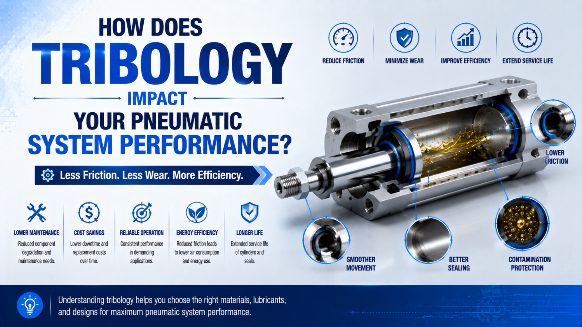
Tribology affects the pressure needed to start a pneumatic cylinder, the stability of low-speed motion, the rate of seal and guide wear, leakage behavior, and the interval between repairs. It is not a material property that can be reduced to one friction coefficient. The result belongs to the complete contact system: seal profile, counterface, pressure, speed, dwell, alignment, lubricant, temperature, and compressed-air contamination.
This distinction changes troubleshooting. A slow or stuttering cylinder does not automatically need oil. The same symptom can come from seal friction, guide side load, insufficient dynamic pressure, a restricted exhaust, a damaged counterface, contaminated grease, or an incompatible replacement seal. Diagnose the contact and the operating state before changing the lubricant.
Key Takeaways
- Friction and wear are system responses, not fixed properties of NBR, polyurethane, PTFE, steel, or aluminum.
- Breakaway friction, running friction, leakage, and stick-slip are different measurements.
- The relation is a useful screening model, not a complete pneumatic-seal model.
- Ra alone cannot define a suitable rod or bore surface; the seal manufacturer’s full counterface specification controls.
- A non-lube cylinder can still contain factory grease, and added airline oil can create a continuing maintenance obligation.
- Life claims need stated test conditions, failure criteria, cycles, and accumulated travel.
What Does Tribology Include in a Pneumatic System?
Tribology is the study of friction, wear, and lubrication where surfaces interact in relative motion. STLE also emphasizes that the materials, geometry, surface features, operating conditions, and environment form one tribological system (STLE, accessed 2026).
In a pneumatic machine, several tribological contacts can act at the same time:
| Contact pair | Intended function | What a tribology problem may look like |
|---|---|---|
| Rod seal against piston rod | Retain pressure while allowing translation | High breakaway force, leakage, lip wear, heat |
| Piston seal against cylinder bore | Separate chambers and transmit pressure force | Internal bypass, speed variation, polished or scored bore |
| Rod wiper against piston rod | Exclude external contamination | Scratched rod, torn wiping edge, debris pulled into gland |
| Wear ring or guide against tube or housing | Carry transverse load and prevent metal contact | One-sided wear, rubbing, rising friction, misalignment |
| Cushion seal or spear against cushion sleeve | Decelerate the piston near end of stroke | End-stroke bounce, impact, localized wear |
| Valve spool and seal system | Route and meter compressed air | Delayed switching, hysteresis, internal leakage |
| Rodless-cylinder sealing band and guides | Seal the slot and support the carriage | Leakage along the slot, drag, uneven carriage motion |
The component producing resistance is not always the component that looks damaged. Side load at the carriage can increase guide friction, tilt the piston, disturb the seal contact, and eventually score the bore. Oil added at the air line may temporarily change motion without removing the mechanical load path.
Treat every pneumatic friction complaint as a contact-pair identification problem before treating it as a lubricant-selection problem. Write down which surfaces move, which surface carries normal load, where pressure energizes a seal, and where debris can enter. That map prevents a valve restriction, bearing problem, or mounting error from being mislabeled as “dry seals.”
Why Is One Friction Coefficient Not Enough?
The coefficient of friction is a property of the tested system and conditions, not a permanent value assigned to one material. STLE notes that wear is also system-dependent and that no universal relationship makes lower friction equal lower wear (STLE Tribology Fundamentals, 2026).
The elementary Coulomb relation is:
Here, is friction force, is the coefficient measured for the specified contact and condition, and is normal load. This model can help compare a controlled sliding pair when load is known and velocity, temperature, surface state, and lubrication are held constant.
A pneumatic seal is more complicated. Its normal contact load can include molded lip interference, elastic deformation, pressure energization, thermal change, and assembly tolerances. Grease shear, seal hysteresis, guide resistance, and the difference between static and running conditions add other effects. The practical question is therefore not “What is the coefficient for polyurethane?” It is “What resistance does this complete cylinder produce at the required pressure, speed, dwell, temperature, and condition?”
Separate at least three values:
- Breakaway force: The peak force needed to initiate motion after a defined dwell.
- Running friction: Resistance during a defined constant-speed interval after acceleration.
- Reversal behavior: The force and delay as motion changes direction and seals reorient.
Use manufacturer sliding-resistance data when it covers the exact model and test condition. Otherwise, measure both cylinder-port pressures and an independently known external load. The residual between net pressure force and external, inertial, and gravity forces can be attributed to assembly resistance within the uncertainty of the test. The cylinder force-loss guide explains that force balance in detail.
How Does Tribology Create Stick-Slip and Unstable Motion?
Stick-slip occurs when pressure buildup, air compressibility, flow restriction, mechanical compliance, and changing friction repeatedly alternate between sticking and sliding. A 2026 experimental study synchronized position, velocity, chamber pressure, and calculated friction for three pneumatic cylinders. It found that conventional velocity-only friction models did not describe every low-speed and dwell-dependent condition (Actuators, 2026).
This is why average stroke time can look acceptable while the workpiece motion is not. The cylinder may stop locally, build differential pressure, jump forward, lose velocity, and repeat. Increasing supply pressure can make the jumps more forceful without removing the friction transition. Opening a meter-out control can change the pressure dynamics, but excessive opening may also reduce motion stability.
Record these signals on one time base:
- motion command or valve command;
- piston or carriage position;
- calculated velocity;
- cap-end and rod-end pressure at the cylinder ports;
- external force when the load can be instrumented;
- dwell time before movement;
- air and component temperature.
Then compare the pressure difference at each stop with the position and velocity trace. If pressure continues to rise while position remains fixed and motion resumes as a jump, friction is part of the mechanism. If commanded flow collapses or exhaust pressure remains high, valve, tubing, flow-control, or silencer restriction may dominate. If motion deteriorates only under one payload or position, investigate alignment, moment, guide load, and counterface damage.
For a full measurement framework, see Quantifying Stick-Slip: The Science Behind “Stuttering” Motion in Cylinders.
How Should Surface Texture Be Specified for Pneumatic Seals?
Specify the counterface with the selected seal and manufacturing process, not with a universal Ra value. ISO 21920-2 defines profile surface-texture terms and parameters, while the acceptable values still come from the seal or cylinder manufacturer for the particular material, profile, pressure, and motion (ISO 21920-2, 2021).
Ra is an arithmetic average. Two surfaces can share the same Ra while having different peaks, valleys, bearing area, lead, and damage potential. Parker therefore discusses parameters including Ra, Rp, Rz, and material ratio, and lists different dynamic counterface recommendations for elastomer, polyurethane, and PTFE seal families (Parker Performance Sealing Products, accessed 2026).
A purchasing or repair specification should identify:
- seal manufacturer, profile, compound, and size;
- rod or bore material, coating, and hardness;
- required texture parameters and evaluation method;
- machining direction and any lead restriction;
- permitted scratches, pits, corrosion, coating pores, and edge damage;
- cleaning and inspection method before assembly.
Too rough is not the only risk. A surface can meet an average roughness value yet contain isolated peaks that cut a lip, deep valleys that create leakage paths, or directional lead that pumps lubricant or gas. Conversely, polishing a surface without the seal supplier’s approval can remove the texture needed by that design or alter geometry.
Do not transfer a finish from one seal family to another. Consult the exact catalog and drawing, then verify the manufactured surface with the specified measurement method. The cylinder barrel honing guide covers bore geometry, crosshatch, and inspection as a separate manufacturing subject.
Does a Non-Lube Cylinder Operate Without Lubricant?
Usually, “non-lube” means the cylinder does not require routine oil mist under its stated conditions; it does not prove that every moving interface is dry. SMC says applicable non-lube cylinders are lubricated at the factory and can operate without added oil. If lubrication is introduced, SMC specifies an approved turbine oil for the relevant products and warns that lubrication must continue because the added oil can displace the original lubricant (SMC MGC Operation Manual, accessed 2026).
Parker likewise describes pneumatic seal arrangements for dry or oil-free air that still receive suitable initial long-life lubrication during assembly (Parker Pneumatic Seals, accessed 2026).
Use the exact product manual to answer four questions:
- What lubricant is applied at the factory?
- Is external oil permitted, optional, required, or prohibited?
- If added oil is permitted, which grade and additive restrictions apply?
- Does starting airline lubrication create a requirement for continuous supply?
If the engineering task is specifically to approve, remove, or change airline oil, use the air-lubrication and seal-material guide for the lubricant-change workflow. This article keeps the wider tribology diagnosis focused on identifying the responsible contact and failure mechanism.
Do not select ZDDP, sulfurized extreme-pressure additives, graphite, PTFE solids, or a “synthetic upgrade” from a general tribology table. An additive useful in a gearbox can be unsuitable for pneumatic elastomers, valves, sensors, exhaust air, clean processes, or the original grease. Compatibility must include the seal compound, base oil, thickener, temperature, air quality, process contamination limit, and manufacturer instruction.
In our experience, a maintenance note that says “cylinder was dry” is not enough to approve an airline lubricator. It may mean that no oil mist was installed, the visible rod carried little grease, a cleaner removed the factory lubricant, or the seal lip actually ran without an adequate film. Record what was cleaned, what grease remained, and which manual applies before changing the lubrication regime.
The self-lubricating seal guide explains the difference between self-lubricating compounds, factory grease, non-lube cylinders, and oil-free compressed air.
How Do Air Quality and Wear Debris Change the Contact?
Compressed air can deliver particles, liquid water, water vapor, oil aerosol, or oil vapor to the moving contact, while external contamination can enter past a damaged or overloaded wiper. ISO 8573-1 defines purity classes for particles, water, and oil, but it does not prescribe one universal class for every actuator (ISO 8573-1, 2010).
Set the point-of-use air requirement from the exact cylinder, valve, process, and environment. Then verify it at the machine under operating conditions. A compressor-room reading does not show contamination released by downstream pipe, incompatible lubricator oil, condensed water at a local low point, or debris introduced during maintenance.
Wear evidence can help separate mechanisms:
| Observation | Possible mechanism | Check before assigning root cause |
|---|---|---|
| Parallel axial scratches on rod or bore | Hard-particle abrasion or embedded debris | Wiper, filter, assembly cleanliness, particle source |
| One-sided guide or piston wear | Side load, angular error, inadequate guidance | Mounting, carriage moment, rod alignment, guide clearance |
| Polished band with rising drag | Contact concentration, swelling, loss of film | Seal compound, cleaner or oil exposure, temperature |
| Torn or rolled lip | Installation damage, pressure direction, groove error | Chamfer, assembly tool, lip orientation, dimensions |
| Corrosion pits beneath the seal path | Water contamination or chemical exposure | Pressure dew point, drainage, material and coating |
| Darkened or hardened grease | Heat, contamination, incompatible lubricant, long service | Temperature history, grease identity, sampling location |
| Leakage with little visible wear | Lip set, pressure energization, surface lead, internal damage | Leakage direction, dwell, pressure, surface metrology |
These are screening clues, not automatic diagnoses. Preserve the failed seal, grease, and debris when the consequence justifies laboratory analysis. Photograph the orientation and wear location before cleaning. If contamination is suspected, sample upstream air and downstream residue separately so a worn polymer particle is not mistaken for incoming dirt.
For selection, connect air-quality evidence with the ISO compressed-air quality guide and verify seal-media compatibility with the pneumatic cylinder seal-material guide.
How Can You Diagnose a Tribology-Related Cylinder Problem?
Change one controlled factor at a time and keep pressure, motion, force, environment, and physical evidence on the same test record. A pneumatic-cylinder friction test apparatus described in the engineering literature measures static, Coulomb, Stribeck, and viscous terms because catalog data or analytical calculation alone may not identify the actual cylinder response (Çukurova University Journal, 2019).
Use this sequence:
- Define the failed requirement. State direction, load, speed, dwell, temperature, position, cycle rate, and the unacceptable symptom.
- Verify the air path. Record valve-inlet pressure and both cylinder-port pressures during the failing event. Check filters, tubing, flow controls, quick exhausts, and silencers.
- Separate the load. Disconnect the machine load where safe, or instrument it. Check mounting alignment, guide preload, transverse load, and moment.
- Capture the friction signature. Record breakaway after a defined dwell, running resistance at specified speeds, reversal behavior, and repeatability in both directions.
- Inspect the contact pair. Examine rod, bore, bands, seals, wiper, guides, grease, and debris without destroying orientation evidence.
- Check configuration records. Confirm the seal kit, compound, counterface specification, lubricant, cleaner, air-quality target, and recent maintenance changes.
- Correct the identified mechanism. Replace damaged parts and correct alignment, contamination entry, surface, lubricant, flow, or pressure conditions as required.
- Repeat the same test. Compare the corrected assembly with the original baseline under the same defined conditions.
If the cylinder drifts, leaks, stalls, or moves slowly in addition to showing friction symptoms, use the pneumatic cylinder troubleshooting guide to test those functions separately.
How Should Tribology Performance Be Specified and Validated?
Convert “low friction” and “long life” into measurable acceptance criteria tied to the application. ISO 19973-3 provides procedures for testing and reporting the reliability of pneumatic cylinders and expresses life in cycles or kilometres under defined conditions (ISO 19973-3, 2015).
A supplier comparison should state:
- cylinder model, bore, stroke, seal and guide configuration;
- pressure at both ports, speed profile, load, orientation, and cycle rate;
- dwell before breakaway and reversal frequency;
- ambient and component temperature;
- compressed-air particle, water, and oil requirements;
- rod and bore material and surface specification;
- lubricant identity and application method;
- sample size, run-in method, and inspection intervals;
- failure thresholds for leakage, friction, motion, wear, and damage;
- results in cycles and accumulated sliding distance.
Do not compare two cycle-life values until stroke, speed, load, pressure, environment, and failure criteria are aligned. A short-stroke test can accumulate many cycles with far less sliding distance than a long-stroke machine. A leakage-based failure threshold also answers a different question from a stick-slip, particle-generation, or guide-wear threshold.
For commissioning, retain a baseline trace of command, position, velocity, and both port pressures. Add breakaway force, external leakage, internal leakage, component temperature, and inspection photographs when the application risk warrants them. That record gives maintenance a transfer function from a vague complaint such as “drag is increasing” to a measurable change.
Conclusion
Tribology affects pneumatic performance through a chain of interacting contacts, not through one universal friction coefficient or lubricant additive. Identify the moving pair, measure the operating state, distinguish breakaway from running friction, and separate air-path restrictions from mechanical resistance. Then use the exact seal, surface, lubricant, and air-quality requirements for the selected component.
The most defensible improvement is not an unsupported percentage. It is a repeatable before-and-after test showing that the corrected system meets its force, motion, leakage, temperature, and life criteria under defined conditions.
FAQs About Tribology in Pneumatic Systems
Tribology questions need configuration-specific answers because friction and wear depend on the complete contact system. The following answers identify the evidence engineers should request before changing a seal, surface, lubricant, or maintenance practice.
Is the coefficient of friction a material property?
No. It is a result measured for a material pair, surface condition, load, speed, temperature, lubricant, environment, and test method. A value for polyurethane or PTFE cannot be transferred automatically to a complete pneumatic cylinder with pressure-energized seals, guides, grease, and alignment effects.
Does a non-lube pneumatic cylinder contain no lubricant?
Not necessarily. Many non-lube cylinders receive factory grease and are designed to operate without routine airline oil under stated conditions. Check the exact manual. If supplemental oil is permitted and introduced, it may displace the original grease and create a requirement for continuous lubrication.
Can an airline lubricator fix pneumatic cylinder stick-slip?
Only if the manufacturer permits lubrication and inadequate lubrication is the verified cause. Stick-slip can also result from low dynamic pressure, exhaust restriction, seal behavior, dwell, misalignment, side load, or surface damage. Measure pressure and motion before altering the lubrication regime.
Is Ra enough to specify a pneumatic seal counterface?
No. Ra does not describe isolated peaks, deep valleys, material ratio, directional lead, hardness, coating defects, or geometry. Use the selected seal manufacturer’s complete counterface specification, including any required Rz, Rp, Rmr, lead, hardness, and process limits.
What measurements belong in a pneumatic tribology diagnosis?
Record the command, position, velocity, both cylinder-port pressures, load or external force, dwell time, direction, temperature, and air condition. Measure breakaway and running resistance separately, then inspect seals, guides, rod, bore, lubricant, and debris while preserving their orientation.
Sources and technical references
-
STLE, Introduction to Tribology. Retrieved 2026-07-27.
-
STLE, Tribology Fundamentals: An Introduction. Retrieved 2026-07-27.
-
Experimental and System-Level Simulation Study of Stick-Slip Characteristics in Pneumatic Cylinders, Actuators 15(5), 2026.
-
ISO 21920-2:2021, Geometrical product specifications, surface texture: Profile, Part 2. Retrieved 2026-07-27.
-
Parker Pneumatic Seals Catalog PTD3351. Retrieved 2026-07-27.
-
Parker Performance Sealing Products, counterface surface finish guidance. Retrieved 2026-07-27.
-
SMC MGC Series Operation Manual. Retrieved 2026-07-27.
-
ISO 8573-1:2010, Compressed air contaminants and purity classes. Retrieved 2026-07-27.
-
ISO 19973-3:2015, Pneumatic fluid power, assessment of cylinder reliability by testing. Retrieved 2026-07-27.
-
Experimental Determination of Friction Characteristics of Pneumatic Cylinders, Çukurova University Journal of the Faculty of Engineering, 2019.