

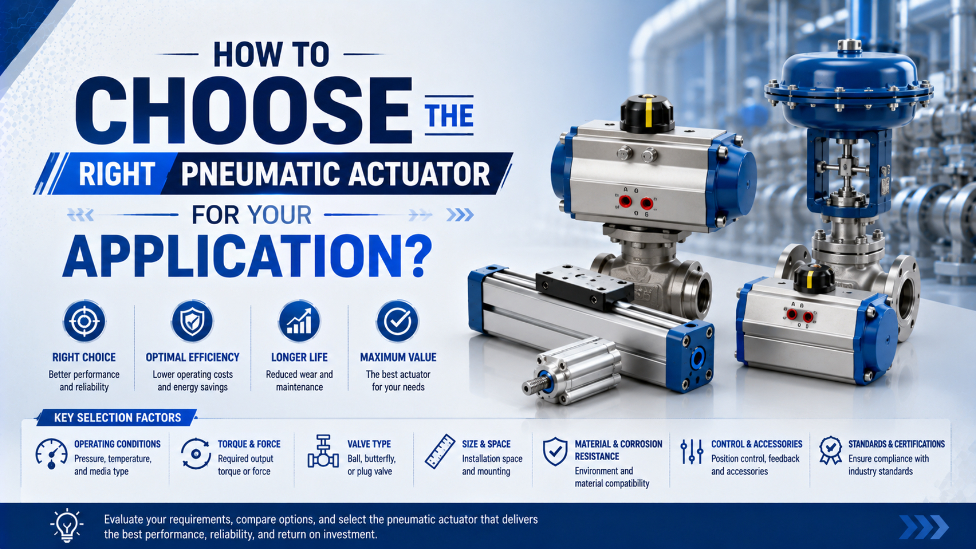
To choose the right pneumatic actuator, define the required motion and safe state before comparing bore sizes or product families. Then check force or torque, load guidance, speed and flow, stopping energy, environment, sensing, and the exact manufacturer’s limits. The pressure-area equation establishes theoretical output, but it does not rate side loads, moments, dynamic response, or failure behavior. SMC’s selection material separates drive-force screening from guide characteristics, while ISO 4414 treats pneumatic safety across design, installation, operation, and maintenance. A valid choice must therefore work at the lowest dynamic pressure, carry every applied force and moment, stop the moving mass, and enter an acceptable state when air or electrical power is lost. The final model is proven by an installed test at the documented worst-case boundary.
Key Takeaways
- Start with the workpiece motion, load path, cycle, and failure state, not a familiar cylinder series.
- Calculate demand from force, gravity, acceleration, friction, and process resistance; compare it with catalog output at the minimum pressure available while moving.
- Keep thrust and load guidance separate. A cylinder can have enough thrust and still fail from side load or an excessive moment.
- Convert stroke time into free-air demand before selecting the valve, tubing, fittings, and exhaust path.
- Verify stopping energy, environment, sensing, mounting, and installed performance before releasing the model for production.
This article is an application-data workflow. If you first need the operating principles and common families, read What Are Pneumatic Actuators and How Do They Work?. For a technology comparison, use the linear actuator guide or the linear vs. rotary actuator guide.
What Information Do You Need Before Selecting an Actuator?
The most useful selection document is a one-page application data sheet. It prevents a supplier from interpreting “move 20 kg quickly” in a way that hides the real load, speed, or safety requirement.
Record these values before comparing products:
| Selection input | Minimum information |
|---|---|
| Motion | Linear, rotary, gripping, clamping, stopping, or indexing |
| Travel | Stroke or rotation angle, usable end positions, installation envelope |
| Moving system | Workpiece, tooling, carriage, cable carrier, hoses, and their centers of gravity |
| Orientation | Horizontal, vertical, inclined, pivoting, or changing during the cycle |
| Process load | Push, pull, clamp, cutting, forming, sealing, or external disturbance force |
| Motion profile | Target travel time, acceleration, deceleration, dwell, and permitted impact |
| Duty | Cycles per minute, operating hours, simultaneous actuators, expected life |
| Air boundary | Minimum dynamic inlet pressure, temperature, air quality, permitted lubrication |
| Guidance | External rail, integrated guide, unsupported load, side forces, and offsets |
| Environment | Dust, washdown, corrosion, cleanroom, food contact zone, temperature, hazardous area |
| Control | Valve state, sensors, intermediate positions, speed adjustment, diagnostics |
| Safe state | Response to loss of air, power, control signal, hose integrity, or component failure |
| Acceptance | Minimum force, maximum stroke time, position window, leakage, noise, and test load |
Use minimum and maximum values rather than one nominal point. A machine may receive 6 bar while idle but only 4.8 bar at the actuator valve during a simultaneous demand peak. Selection against the idle gauge reading can produce a cylinder that stalls only when production is busiest.
Treat the data sheet as a boundary contract. Every calculation, catalog lookup, quotation, and acceptance test should refer to the same load, pressure, orientation, speed, and environment. If one boundary changes, the selection must be checked again.
Minimum dynamic pressure is the lowest pressure available at the relevant valve inlet or actuator chamber while the specified movement occurs. It is more useful for force selection than compressor set pressure or an idle gauge reading.
Actuator Family Selection Starts with Motion and Load Path
Select the mechanical architecture before calculating a final bore. The actuator should create the required motion without being forced to act as a guide, bearing, brake, or safety restraint unless the product was designed and rated for that function.
| Application condition | Actuator family to evaluate | Critical verification |
|---|---|---|
| Straight push or pull with an external guide | Single-rod cylinder | Rod buckling in compression, alignment, mounting reaction |
| Compact guided transfer or pressing table | Guided or twin-rod cylinder | Permissible forces, moments, deflection, bearing type |
| Long stroke with limited axial installation space | Mechanically coupled rodless cylinder | Guide load, sealing band environment, combined-load rule |
| Sealed long-stroke motion with limited drive force | Magnetically coupled rodless cylinder | Magnetic coupling limit, decoupling consequence, external guidance |
| Limited-angle rotation | Vane or rack-and-pinion rotary actuator | Torque curve, inertia, angle, backlash, shaft loads, stopping energy |
| Workpiece gripping | Parallel, angular, or three-jaw gripper | Grip force at actual finger length, jaw moments, loss-of-pressure behavior |
| High-repeatability multi-position motion | Servo-pneumatic or electric axis | Feedback, tuning, load variation, accuracy and settling requirement |
| Holding a vertical load | Cylinder plus a rated holding solution | Risk assessment, stopping distance, lock/brake behavior, release logic |
A standard single-rod cylinder usually needs an external guide when tooling applies side load or an offset moment. A guided cylinder combines drive and guidance, but its table still has finite force, moment, deflection, speed, and life limits. SMC’s guided-cylinder selection material states that load, accuracy, and deflection vary with model, bore, speed, and overhang (SMC Guided Cylinder Characteristics, accessed 2026). Rodless does not mean unlimited load capacity: a basic rodless cylinder may only transmit motion, while a guided series can carry a catalog-defined combination of loads and moments. Anti-rotation is narrower still. A non-round rod, twin rods, or guide rods can resist rotation, but that feature alone does not establish linear accuracy, stiffness, or repeatability. Those properties require product-specific bearing, deflection, mounting, load-offset, and sensing data.
How Do You Calculate the Required Linear Force?
For a double-acting single-rod cylinder, theoretical extension and retraction forces are:
where:
- and are theoretical forces in newtons;
- and are chamber gauge pressures in pascals;
- is piston area in square metres;
- is rod area in square metres;
- is bore diameter and is rod diameter in metres.
These equations describe pressure acting on effective area. They do not include seal resistance, backpressure, acceleration, gravity, misalignment, or process force. Use the lowest chamber pressure expected during the movement, not compressor set pressure.
Build the demand in the direction of travel:
Here, is equivalent moving mass, is required acceleration, is gravitational acceleration, is the travel angle measured from horizontal, and the other terms represent process, friction, and credible external forces opposing motion. Use signs consistently. A descending vertical load, for example, can be an overrunning load rather than a simple addition to cylinder thrust.
For a horizontal axis, the load’s weight is carried by the guide; it is not automatically the horizontal drive force. The horizontal calculation needs guide friction, acceleration, cable and hose drag, seal resistance, slope, and process force. Converting a 50 kg horizontal load directly into 490 N of horizontal resistance would therefore be incorrect.
The calculator is a pre-selection tool. Do not treat its default allowances as a manufacturer rating. SMC’s general cylinder guide, for example, uses different load-factor examples for stationary operation, dynamic operation, and guided horizontal motion, and calls for further reduction in demanding high-speed service (SMC Air Cylinder Selection Guide, accessed 2026). Apply the rule published for the selected series and duty rather than a universal percentage.
A corrected 40 mm bore example
Suppose a 40 mm bore rodless cylinder is being screened at a measured 6 bar chamber pressure:
The result is 754 N theoretical drive force. It does not prove that the actuator can move a 50 kg carriage. The application still needs the acceleration, guide friction, cable drag, process force, minimum dynamic pressure, and product-specific selection factor. Its guide must also carry the vertical weight and every offset moment.
How Should Side Loads and Moments Be Checked?
Separate drive force from guide loading. Start with a coordinate system attached to the candidate actuator, then place every moving mass and external force at its actual center of action. Include tooling plates, brackets, cable carriers, hoses, workpieces, and forces from the process.
For one force acting at a perpendicular distance:
where is moment in newton-metres, is force in newtons, and is the perpendicular offset in metres. Calculate all relevant force and moment components, then apply the catalog’s combined-load method.
Some guided and rodless actuator catalogs use a sum of load ratios:
is one applied force or moment and is its permissible value at the stated speed, stroke, mounting, and load center. Use this equation only when the selected manufacturer specifies that combination rule and its acceptance limit. Do not invent an axial/side/moment table from bore alone.
Combined-load utilization is a catalog-defined comparison between simultaneous applied loads and the corresponding permissible loads. Its axes, equation, speed correction, and pass limit belong to the exact actuator series; they cannot be transferred safely from another model.
SMC’s MY2C catalog requires consideration of piping and cable-carrier forces and states that travel parallelism is not guaranteed by the actuator itself (SMC MY2C Catalog, accessed 2026). That is a useful general lesson: small external loads and accuracy requirements can control the design even when the main workpiece mass looks acceptable.
The side-loading guide explains why a floating joint can correct limited alignment error but cannot replace a load-bearing guide.
Stroke Time, Air Flow, and Valve Selection
Target speed cannot be selected independently of the valve and air path. For a cylinder stroke completed in time , the ideal average chamber volumes and flows are:
is volume per time at chamber conditions. Most valve and compressor comparisons use normalized or free-air flow, which requires an absolute-pressure conversion:
where is normalized flow, is absolute chamber pressure, is the stated reference pressure, and temperatures are absolute. Confirm the supplier’s reference conditions because “NL/min,” “ANR,” “SCFM,” and free-air delivery are not interchangeable without those conditions.
For a 40 mm piston moving at 0.5 m/s, ideal chamber flow is about 37.7 L/min. At roughly 6 bar gauge, or 7 bar absolute, the ideal free-air equivalent is approximately 264 NL/min before dead volume, leakage, pressure transients, and margin. Reporting only 38 L/min without its pressure basis can lead to a severely undersized valve.
Use the Cylinder Flow Requirement Calculator to screen extend and retract demand from bore, rod, stroke, target time, and pressure. Then verify:
- valve flow data at the expected upstream and downstream pressures;
- manifold, fitting, tube, and cylinder-port restrictions;
- meter-out controller and silencer capacity;
- supply pressure during simultaneous actuator events;
- minimum and maximum stable cylinder speed;
- acceptable stroke-time variation as load and pressure change.
The simple relationship is a kinematic screen, not a complete pneumatic motion model. Air compressibility, changing chamber pressure, valve switching, breakaway friction, backpressure, and cushioning shape the actual velocity profile.
How Do You Size a Rotary Actuator?
Rotary selection begins with torque and inertia, not the mass alone:
where is load inertia about the rotation axis, is angular acceleration, and the remaining terms are gravity, friction, and process torques. Include couplings, shafts, tooling, and the workpiece at their actual radii.
Compare demand with the actuator’s torque at the minimum dynamic pressure and throughout the required angle. Rack-and-pinion and vane designs may have different torque characteristics, backlash, allowable shaft loads, and end-stop arrangements. Average output torque is not enough if the mechanism has a high breakaway load or a gravity peak at one angle.
The Pneumatic Rotary Actuator Torque Calculator can organize inertia, angular acceleration, gravity orientation, friction, efficiency, and selection allowance. The final check still needs the exact torque curve, rotation time, allowable kinetic energy, shaft load, stop method, and duty data.
Can the Actuator Stop the Moving Load Safely?
Thrust sizing answers whether an actuator can accelerate the load. Cushion sizing answers whether it can absorb the remaining energy at the end of travel.
Start with translational kinetic energy:
is the equivalent moving mass at the actuator and is approach velocity at the start of deceleration. For rotary motion, use . Add work done by gravity or an external driving force through the stopping distance when it continues to accelerate the load.
Check the candidate’s permissible kinetic energy at the actual speed, load, cushion option, and mounting. Adjustable pneumatic cushioning needs enough pressure and adjustment range; an elastic bumper is not equivalent to a hydraulic shock absorber. If an external shock absorber is used, verify its per-stroke energy, hourly energy, effective mass, return time, alignment, and rated temperature.
Do not use the cylinder’s physical end cap as a production stop unless its catalog explicitly permits the calculated duty. A hard impact can loosen mounting hardware, damage seals, bend tooling, and introduce rebound that sensors misread as a completed position.
What Environmental and Interface Conditions Change the Answer?
An actuator that passes the mechanical calculation can still be unsuitable for the plant. Match every material and accessory to the installed environment:
- Temperature: verify seals, grease, sensors, cushioning, tubing, and speed across start-up and steady operation.
- Dust and chips: protect exposed rods, sealing bands, guides, and sensors; do not assume a scraper excludes every contaminant.
- Water and chemicals: specify corrosion resistance and washdown-compatible sensors, connectors, lubricants, and mounting hardware.
- Cleanroom or food production: request product-specific emissions, lubricant, material, and cleaning documentation for the actual zone.
- Hazardous areas: assess the complete electrical and mechanical assembly, not only the cylinder body.
- Air quality: state particle, water, and oil requirements plus whether downstream lubrication is prohibited, optional, or mandatory.
- Space and access: allow room for ports, fittings, sensors, cushion screws, rod removal, sealing-band service, and lock release.
ISO 15552 defines basic, mounting, and accessory dimensions for a family of detachable-mounting cylinders up to 10 bar; its purpose is dimensional interchangeability (ISO 15552:2018, confirmed 2025). An ISO mounting pattern does not prove equal force margin, rod diameter, cushioning energy, sensor groove, material, leakage, or service life. Replacement review must compare those characteristics separately.
Port size is also not a flow rating. Two valves or actuators with the same thread may have different internal passages. Use pressure-flow data and the complete path rather than choosing tubing from the port label alone.
What Does Safe Failure Require?
Write the required state for each credible loss before choosing the circuit:
- loss of compressed air;
- loss of electrical power;
- broken or disconnected tube;
- stuck valve or sensor;
- internal leakage;
- maintenance isolation and residual pressure;
- restart after pressure or power returns.
ISO 4414 addresses significant hazards in pneumatic systems and applies safety principles to design, installation, adjustment, operation, maintenance, and modification (ISO 4414:2010, confirmed 2021). The machine risk assessment determines which measures and performance level are necessary.
Trapping air with a closed-center valve or pilot-operated check valve may slow movement, but leakage, tube failure, compressibility, and valve failure remain. It is not automatically a personnel-protection holding function. A vertical or suspended load may require a mechanically rated rod lock, brake, counterbalance arrangement, blocking device, or another engineered restraint with monitored control and a defined release sequence.
Stored pneumatic energy must be considered during isolation. Provide a way to isolate, dissipate, verify, and prevent unexpected restoration of energy according to the machine’s safety design. Also control the load while pressure is being exhausted; rapid dumping can create the hazard it was intended to remove.
How Should Sensors, Controls, and Mounting Be Specified?
End-position switches confirm that a magnet entered a sensing window. They do not prove full mechanical seating, adequate clamp force, or safe load restraint. Specify what the control system actually needs to know:
- end-position presence or confirmed mechanical state;
- intermediate position or continuous feedback;
- permitted repeatability and response time;
- diagnostic coverage for disconnected or stuck signals;
- connector, cable, voltage, and environmental rating;
- behavior during manual operation, commissioning, and restart.
Mounting determines the load path. Fixed mounts need alignment through the entire stroke. Pivot mounts need compatible rod-end joints and enough angular freedom. Long push strokes need a rod-buckling check, while an externally guided load needs a coupling that does not force small guide errors into the cylinder bearings.
In our experience, the most revealing application drawing is often a side view showing the actuator, guide, load center, hose loop, and mounting surfaces together. It exposes offsets and reaction paths that disappear from a parts list. The drawing still needs dimensions and catalog checks; it is not a substitute for them.
Use a Ten-Gate Selection Review Before Ordering
Pass each gate with a calculation, catalog page, drawing, or test requirement:
| Gate | Pass condition | Evidence to retain |
|---|---|---|
| 1. Motion | Family produces the required travel or angle inside the envelope | Layout and motion profile |
| 2. Drive output | Force or torque exceeds demand at minimum dynamic pressure | Calculation and catalog curve |
| 3. Guidance | All forces, moments, offsets, and deflection are acceptable | Load diagram and combined-load check |
| 4. Speed | Valve-to-actuator path supplies required free-air flow | Flow calculation and component data |
| 5. Stopping | Cushion, stop, or shock absorber accepts event and hourly energy | Energy calculation and rating |
| 6. Duty | Cycle rate, thermal state, and expected life fit the product | Duty statement and manufacturer confirmation |
| 7. Environment | Materials, seals, lubricant, sensors, and ingress protection fit | Environmental specification |
| 8. Safety | Loss states and stored energy meet the risk assessment | Circuit, risk review, validation plan |
| 9. Interface | Mounting, ports, sensors, access, and replacement constraints fit | Controlled drawing and BOM |
| 10. Acceptance | Installed machine can prove output and behavior | Test procedure and limits |
Do not release a model because nine gates pass. A failed stopping-energy or safety gate can be more important than a large thrust margin.
What should an RFQ include?
Send suppliers the boundary data rather than only a legacy part number:
- application function and motion profile;
- moving masses and centers of gravity;
- force, moment, inertia, and external-load diagrams;
- stroke or angle, target time, dwell, and cycle rate;
- minimum dynamic pressure and air-quality limits;
- mounting orientation, guide arrangement, and available envelope;
- temperature, contamination, cleaning, and corrosion conditions;
- sensor, connector, valve, and speed-control requirements;
- safe state and applicable machine-safety requirements;
- acceptance criteria and required documentation.
Ask the supplier to return the selected model, configuration code, assumptions, force or torque margin, permissible-load check, stopping-energy check, flow basis, exceptions, and service requirements. This makes competing quotations comparable.
How Do You Validate the Installed Actuator?
Installed actuator validation is a controlled test of the selected motion system at its documented worst-case boundary. Use the lowest credible supply pressure, maximum permitted payload, worst orientation, representative temperature, and simultaneous demand state. Measure dynamic pressure and travel time rather than relying on an idle gauge. Check guide behavior, stopping, sensor sequence, leakage, loss of air or power, isolation, exhaust, and restart. The purpose is to prove that the actuator, valve, air path, mounting, controls, and load behave as one system. Record the instruments, test load, software state, regulator and cushion settings, acceptance limits, deviations, and approval. A catalog calculation remains necessary, but it cannot reproduce installation tolerances, hose drag, backpressure, production timing, or the machine’s actual failure response.
Test at the lowest credible supply pressure, maximum permitted payload, worst orientation, representative temperature, and simultaneous demand state. Record:
- valve inlet and relevant chamber pressure during travel;
- extend, retract, or rotation time over repeated cycles;
- minimum position or clamp-force requirement;
- end-of-stroke impact, rebound, and cushion setting;
- guide behavior, deflection, binding, and unusual temperature;
- sensor sequence and fault response;
- air-loss, power-loss, isolation, exhaust, and restart behavior;
- leakage and noise limits where specified.
Freeze the final regulator, flow-control, cushion, stop, and sensor settings. Record the test load, instruments, pressure boundary, software state, deviations, and acceptance signature. If the production boundary differs from the quotation boundary, update the selection record rather than treating the first model number as permanent.
Conclusion: Select the Whole Motion System
The right pneumatic actuator is the one that passes the complete application boundary. Define the motion and safe state, calculate force or torque at the minimum dynamic pressure, map every guide load and offset, convert travel time into free-air demand, and check stopping energy.
Then verify the environment, interfaces, sensing, duty, maintenance access, and failure response. Use ISO dimensions for interface control, but use the exact product catalog for performance. Finish with an installed worst-case test and retain the settings and evidence.
This approach may lead to a larger bore, a guided cylinder, a rodless axis, a rotary actuator, an external guide, or a different technology entirely. That is the purpose of selection: choose the architecture that satisfies the machine, rather than forcing the machine into a familiar component.
Pneumatic Actuator Selection FAQs
Is bore size enough to choose a pneumatic cylinder?
No. Bore determines theoretical pressure-area force, but selection also needs rod area, minimum dynamic pressure, load orientation, acceleration, friction, process force, side loads, moments, speed, stopping energy, mounting, environment, and safe-state requirements. Final limits must come from the exact series catalog.
What pressure should I use for actuator sizing?
Use the lowest pressure expected at the valve or actuator chamber during the movement being designed. Compressor set pressure or an idle regulator gauge can overstate available force when filters, valves, tubing, fittings, simultaneous demand, and exhaust backpressure are included.
Can a pneumatic cylinder carry a side load if it has enough force?
Drive force does not establish guide capacity. A standard cylinder generally needs external guidance for significant side load or offset moment. A guided or rodless actuator can carry only the force and moment combination permitted for its exact model, stroke, speed, mounting, and load center.
How do I know whether the selected valve is large enough?
Calculate the extend and retract free-air demand from effective area, stroke, target time, absolute pressure, and reference conditions. Then compare it with valve and complete-path flow data at the expected pressure ratio. Confirm performance by measuring dynamic pressure and stroke time on the installed machine.
Sources and Technical References
- ISO 4414:2010, Pneumatic fluid power: General rules and safety requirements for systems and their components
- ISO 15552:2018, Pneumatic fluid power: Cylinders with detachable mountings
- SMC, Air Cylinder Selection Guide
- SMC, Basic Characteristics of Cylinders with Guide
- SMC, MY2C Mechanically Jointed Rodless Cylinder Catalog