

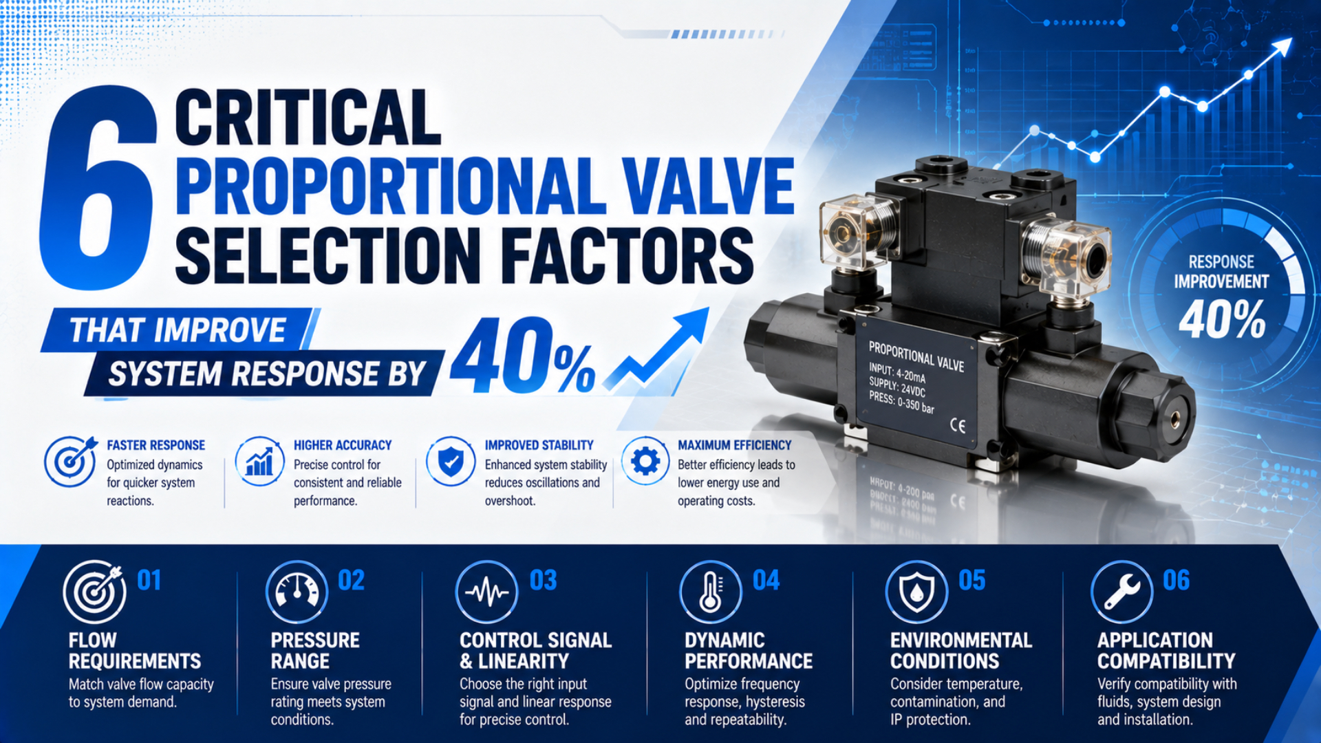
A proportional valve can make a pneumatic system respond faster, but no valve specification guarantees a 40% improvement. That number must come from a controlled comparison on the same machine. The load, tubing, pressure, command step, sensor location, controller settings, and acceptance limits must remain consistent before and after the change.
Valve selection still matters. The wrong valve may saturate before the required flow, react quickly while the cylinder remains slow, deliver different outputs on rising and falling commands, or enter an unsafe state when its signal disappears. A well-matched valve removes one bottleneck without hiding another.
Festo’s MPYE family illustrates the range inside one proportional directional-valve series: nominal flow spans 100 to 2,000 L/min, while its model-dependent 3 dB limit frequency spans 70 to 115 Hz (Festo MPYE Datasheet, 2025). The six factors below show how to compare that data without turning a catalog number into a machine-level promise.
Key Takeaways
- Treat 40% as a measured project result, not a universal valve benefit.
- Choose pressure, flow, or directional control before comparing response data.
- Verify capacity in both supply and exhaust directions.
- Compare hysteresis, signals, failure state, EMC, and environmental limits under stated conditions.
Can Six Valve Factors Really Improve Response by 40%?
SMC lists a 0.1 s response time for its compact ITV regulator without load and says the value is not guaranteed because operating conditions affect it (SMC ITV Catalog, 2024). A 40% improvement is credible only when a repeatable before-and-after test demonstrates it.
Define the response metric first. It might be command-to-pressure settling time, command-to-flow settling time, cylinder stroke time, or command-to-in-position time. Those measurements end at different points in the control chain. They cannot be exchanged without changing the claim.
For a response-time metric, calculate improvement as:
Here, is the measured improvement, is baseline response time, and is response time after the change. Both times must use the same start trigger, end threshold, command amplitude, load, supply pressure, tubing, temperature, and sample rate.
A reduction from a hypothetical 100 ms baseline to 60 ms produces a calculated improvement of 40%. That arithmetic does not prove that a particular valve will deliver it. It only shows how to report a measured result without ambiguity.
The most useful improvement claim names its measurement boundary. “Valve spool response improved by 40%” may leave cylinder motion unchanged. “Command-to-in-position time improved by 40% at the production payload” covers more of the system, but it must also state settling tolerance, overshoot limit, and test conditions.
Factor 1: Control Objective Comes Before Valve Type
ISO 10041-1 specifies supplier-literature characteristics for electro-pneumatic continuous flow-control valves, while ISO 10094-1 covers electro-pneumatic pressure-control valves (ISO 10041-1, 2010; ISO 10094-1, 2021). The split matters because speed, pressure, force, and position require different valve and feedback architectures.
Start with the variable the process must control:
| Process objective | Typical proportional component | What the electrical command changes | Feedback needed for process-level closed loop |
|---|---|---|---|
| Adjustable pressure | Proportional pressure regulator | Regulated outlet pressure | Pressure sensor, often internal |
| Adjustable cylinder speed | Proportional flow valve | Metering restriction or commanded flow | Position or velocity sensor when load-independent speed matters |
| Bidirectional motion | Proportional directional valve | Direction and metering opening | Position or velocity sensor for closed-loop motion |
| Controlled contact force | Pressure regulator or directional valve in a force loop | Pressure or port opening | Load cell or force sensor when actual force must be controlled |
A proportional pressure regulator can regulate pressure at its sensor. It does not directly regulate cylinder force because piston area, opposing chamber pressure, seal friction, linkage geometry, and contact conditions remain outside its internal loop. The proportional pressure regulator guide explains that boundary in detail.
A proportional flow valve can shape velocity, yet open-loop speed still changes with load, pressure ratio, friction, and exhaust back pressure. A proportional directional valve can meter both actuator chambers, but repeatable mid-stroke positioning usually needs continuous position feedback and a controller.
This first decision prevents an expensive category error. If the process needs position, buying a fast pressure regulator will not create a position loop. If it needs pressure, a high-bandwidth directional valve may add complexity without measuring the controlled variable.
Factor 2: How Much Flow Must the Valve Pass?
Festo lists MPYE nominal flow values of 100, 350, 700, 1,400, and 2,000 L/min across five nominal sizes (Festo MPYE Datasheet, 2025). Those values show why port thread alone is not a capacity specification. Select from flow data measured at declared pressure and reference conditions.
The valve must fill one actuator chamber while the opposite chamber exhausts. Both paths affect response. A large supply opening cannot overcome a restricted silencer, undersized exhaust passage, narrow tube, long manifold gallery, or small cylinder port.
For a pressure regulator, review forward-flow and relief-flow characteristics separately. A regulator that fills quickly may reduce pressure slowly if its exhaust capacity is limited. For a directional valve, compare metering behavior around neutral as well as maximum flow. For a two-port flow valve, confirm whether the published curve applies to the required direction.
ISO 6358-1 provides steady-state methods for pneumatic components using compressible fluids and describes flow characteristics rather than treating air like an incompressible liquid (ISO 6358-1, 2013, with 2020 and 2026 amendments). Use the manufacturer’s sonic conductance, critical pressure ratio, standardized flow, or declared pressure-flow curves when available.
Do not rank pneumatic proportional valves with one bare Cv value unless both suppliers define the same medium, reference state, pressure ratio, direction, and valve command. The simple liquid relationship often associated with Cv does not represent choked gas flow, varying density, or a modulating valve’s command-dependent opening.
The required-flow review should include:
- minimum pressure available at the valve during the move;
- downstream or exhaust pressure during peak flow;
- tube inside diameter, length, fittings, manifolds, and silencers;
- actuator chamber volume throughout the stroke;
- required move time and allowable acceleration;
- simultaneous demand from other branches;
- supply and exhaust behavior at the actual command range.
If cylinder response remains slow after installing a larger valve, the next restriction may be in the tubing or actuator port. The cylinder response-time and dead-volume analysis helps separate those delays.
Factor 3: Which Dynamic Specification Matters?
Festo specifies MPYE model-dependent 3 dB limit frequencies of 70, 80, 95, and 115 Hz, while SMC describes an ITV response time of 0.1 s without load (Festo MPYE Datasheet, 2025; SMC ITV Catalog, 2024). These numbers describe different valves, outputs, and tests, so they are not interchangeable rankings.
Ask what moved and what was measured. A frequency limit related to valve-spool travel is not cylinder-position bandwidth. A regulator’s outlet-pressure response is not its internal armature response. A machine’s in-position time includes valve delay, air propagation, chamber filling, load acceleration, friction, mechanical settling, sensing, and PLC logic.
At minimum, a comparable step-response record needs:
- Valve model, size, firmware, and controller configuration.
- Input type, initial command, final command, and command direction.
- Supply pressure, downstream pressure, and exhaust condition.
- Connected volume, tube length, tube ID, actuator, and payload.
- Measured output and sensor location.
- Sample rate, filtering, start trigger, and time origin.
- Definitions for delay, rise time, overshoot, and settling band.
- Temperature and air-quality conditions.
Overshoot can be reported as:
Here, is percent overshoot, is the maximum response after the step, and and are the declared steady values. The same definition, filtering, observation window, and command direction must be used for every candidate.
The fastest valve is not always the best choice. A high-bandwidth valve can expose pressure oscillation, mechanical resonance, sensor noise, or controller tuning limits. Select enough dynamic authority for the required profile, then validate the complete pneumatic axis.
Factor 4: How Do Hysteresis and Deadband Affect Response?
Festo states maximum MPYE hysteresis of 0.4% relative to maximum spool travel, whereas SMC states PVQ flow hysteresis of 10% or less (Festo MPYE Datasheet, 2025; SMC PVQ Catalog, accessed 2026). The percentages refer to different measured outputs and cannot be compared as though they were the same specification.
Hysteresis asks whether output differs at the same command when the command approaches from opposite directions. Deadband asks how far the input can move before a defined output response appears. Linearity compares a measured characteristic with a declared reference line. Repeatability measures agreement across repeated approaches under the same conditions.
Each term can affect response in a different way:
| Characteristic | Response symptom | Evidence to request |
|---|---|---|
| Hysteresis | Different pressure, flow, or spool position at the same rising and falling command | Full up-and-down curve, output variable, normalization basis |
| Deadband | Delay or no response around neutral or reversal | Threshold definition, positive and negative directions |
| Linearity | Command gain changes across the range | Reference-line method and measured curve |
| Repeatability | Response changes across repeated identical commands | Trial count, direction, conditions, and statistic |
| Resolution or sensitivity | Small commands disappear into quantization or noise | Input increment, output threshold, filtering, and instrumentation |
The dedicated hysteresis and linearity guide shows why percentages need a common test basis. Use that analysis instead of hiding every nonlinear effect under the word accuracy.
Dead-zone compensation should follow the valve and controller documentation. A fixed offset may help a repeatable threshold, but too much offset can create a command jump or limit cycle. External dither may conflict with internal current control, built-in compensation, or thermal limits. Do not apply a universal percentage or frequency.
Internal spool feedback can reduce command-to-spool error, yet it does not measure downstream pressure, mass flow, cylinder velocity, or part position. The spool-position feedback guide separates the internal valve loop from the outer machine loop.
A nonlinear but repeatable valve may be characterized and controlled. A valve whose response changes with direction, temperature, contamination, or pressure may be harder to compensate because one command no longer maps reliably to one output. Stability across conditions can matter more than an attractive single-point response time.
Factor 5: Signal, Feedback, and Failure State
Festo’s MPYE accepts model-specific 0 to 10 V or 4 to 20 mA setpoints, operates from 17 to 30 V DC, and permits 5% residual ripple (Festo MPYE Datasheet, 2025). Matching the connector is not enough; signal scaling, grounding, diagnostics, interruption behavior, and available feedback must also match the controller.
A voltage command is simple, but voltage drop, ground offset, and coupled noise can alter the value seen at the valve. A current loop is usually less sensitive to voltage drop and can make an open circuit easier to detect, but the PLC output, valve input impedance, wiring, and fault thresholds still need confirmation.
Check these electrical fields before ordering:
- supply-voltage range and inrush or steady current;
- analog command type, scaling, impedance, and polarity;
- command common and power common arrangement;
- permitted ripple and noise;
- connector pinout and shield termination;
- actual-value output, diagnostic output, or fieldbus objects;
- behavior below and above the valid command range;
- behavior after command loss, power loss, overtemperature, or internal fault.
The word feedback can be misleading. A valve may close an internal loop around spool position or outlet pressure without exposing the actual value to the PLC. A separate analog monitor may report a process variable but not participate in control. Ask for the interface diagram and object list, not just “closed loop” in the product description.
Failure state must be reviewed mechanically and pneumatically. Festo says the MPYE moves to its closed mid-position if the supply cable is interrupted in the cited reliability data, but that component behavior does not prove that an actuator stops safely or holds load. Trapped air, leakage, external forces, valve overlap, and stored energy remain machine-level concerns.
For safety-related behavior, define the required risk-reduction function independently. A normal proportional control channel, feedback signal, or EMC declaration is not automatically a safety function.
Factor 6: What Environment and EMC Evidence Is Required?
Festo specifies IP65, 0 to 50°C ambient temperature, and compressed-air quality ISO 8573-1 class 6:4:4 for MPYE operation (Festo MPYE Datasheet, 2025). These limits affect response and reliability before EMC is considered, so the environmental check must cover air, temperature, ingress, vibration, wiring, and electrical disturbances.
IEC 61000-6-2:2016 is the generic immunity standard for industrial environments when no relevant dedicated product or product-family standard exists (IEC 61000-6-2, 2016). IEC 61000-4-3 covers radiated radio-frequency immunity testing, while IEC 61000-4-4 covers electrical fast transient or burst testing (IEC 61000-4-3, 2020; IEC 61000-4-4, 2012).
Those IEC 61000-4 documents are test methods. They establish test levels and procedures, but the applicable product or generic standard determines which tests, port conditions, levels, and performance criteria are required. Avoid a vague requirement such as “Level 4 EMC valve.”
Instead, ask the supplier for:
- The declaration of conformity and the standards actually applied.
- The exact product code and electronics version covered.
- Port-specific test levels for enclosure, power, signal, and communication ports.
- Performance criteria during and after each disturbance.
- Cable type, length, shielding, grounding, and external filters used in testing.
- Any installation restrictions needed to maintain conformity.
Valve conformity does not establish machine conformity. Long analog cables, shared power supplies, welding currents, variable-frequency drives, poor shield termination, and ground-potential differences can degrade the installed system. The final machine needs an EMC design and validation process appropriate to its market and risk.
Pneumatic conditions matter too. Contamination can increase friction and change deadband. Temperature changes coil resistance, seal behavior, electronics, and air density. Supply-pressure variation changes flow authority. A response specification should therefore be tested across the expected operating envelope, not only at a laboratory midpoint.
A Six-Factor Supplier Comparison Matrix
One Festo MPYE family spans five nominal flow values, two common command types, four listed 3 dB frequency values, and a stated 0.4% maximum spool-travel hysteresis (Festo MPYE Datasheet, 2025). A useful supplier matrix keeps those fields separate instead of collapsing them into a single “fast and accurate” label.
| Selection factor | Supplier A | Supplier B | Acceptance evidence |
|---|---|---|---|
| 1. Controlled variable and valve type | Pressure, flow, or directional | Pressure, flow, or directional | Functional diagram and measured process variable |
| 2. Flow capacity | Supply and exhaust curves at stated pressures | Same basis required | Catalog curves plus production pressure data |
| 3. Dynamic response | Metric, amplitude, volume, load, filtering | Same method required | Raw trace and declared thresholds |
| 4. Hysteresis and deadband | Output variable, direction, range | Same definitions required | Up/down characteristic and neutral-region test |
| 5. Signal and failure state | Input, feedback, diagnostics, power-loss state | Same interface scope required | Wiring diagram, object list, fault test |
| 6. Environment and EMC | Temperature, air class, IP, applied standards | Same installation assumptions required | Data sheet, declarations, and test evidence |
Do not average these six rows into one score without weighting them. A high-flow valve that fails the required power-loss state is not rescued by good bandwidth. A low-hysteresis valve that cannot exhaust the actuator fast enough still misses the move-time target.
Use a pass/fail gate for non-negotiable requirements, then rank the surviving candidates on engineering margin, documentation, maintainability, supply risk, and cost. This keeps marketing language from compensating for a missing safety or performance requirement.
How Should the Valve Be Tested on the Machine?
ISO 10094-2:2021 standardizes comparison tests for electro-pneumatic continuous pressure-control valves and states that those tests are not production tests for every manufactured component (ISO 10094-2, 2021). The machine builder still needs an acceptance test that includes the installed tubing, volume, load, sensors, controller, and environment.
Use the following sequence:
- Freeze the test definition. Name the commanded step, measured output, trigger, thresholds, settling band, overshoot limit, sample rate, filtering, and pass criteria.
- Record the baseline. Capture multiple cycles at normal pressure, temperature, load, and production timing. Preserve raw data, not only screenshots.
- Change one controlled element. If the valve, tubing, controller gain, and silencer all change together, the result cannot isolate the selection decision.
- Repeat under the same conditions. Use the same payload, pressure, command profile, sensor, and data-processing method.
- Test the operating envelope. Include minimum supply pressure, maximum payload, cold start, warmed operation, and both movement directions.
- Test abnormal conditions. Verify signal loss, power loss, blocked or restricted exhaust, diagnostic response, and restart behavior within the machine risk assessment.
- Calculate the result. Report mean, spread, worst case, overshoot, settling, and the improvement formula rather than one favorable trace.
What if the new valve is faster but overshoots more? The acceptance criteria must decide whether the trade is acceptable before testing starts. A shorter initial rise time is not an improvement if the process takes longer to settle or produces an unsafe pressure peak.
For cylinder motion, capture command, valve actual value when available, upstream and downstream pressure, cylinder position, and the PLC in-position bit on the same time base. That trace shows where delay accumulates. It also prevents a fast electrical response from being mistaken for a fast mechanical result.
The best acceptance trace has enough signals to falsify the preferred explanation. If the valve command changes immediately but chamber pressure moves late, look at flow capacity and dead volume. If pressure changes but position does not, inspect friction, load, mechanics, or the position loop.
Better Response Comes From Matching the Whole Chain
Festo’s MPYE data combines 100 to 2,000 L/min nominal flow, 70 to 115 Hz limit frequency, 0.4% maximum spool-travel hysteresis, and model-specific electrical inputs (Festo MPYE Datasheet, 2025). None of those values alone predicts the final motion or pressure response of an installed pneumatic machine.
Select the controlled variable first. Then verify supply and exhaust capacity, dynamic test definitions, hysteresis and deadband, electrical interfaces, failure state, environmental limits, and EMC evidence. Eliminate candidates that miss a non-negotiable requirement before comparing price or headline speed.
A 40% response improvement is meaningful when the baseline, modified system, measurement boundary, conditions, and calculation are documented. Without those details, it is marketing language. With them, it becomes a reproducible engineering result.
For the broader architecture decision, use the proportional-valve motion-control guide. This article’s six-factor matrix then provides the narrower response and acceptance framework for comparing actual candidates.
Proportional Valve Selection FAQs: What Should Engineers Ask?
Festo’s MPYE series alone spans five nominal flow values from 100 to 2,000 L/min and four listed 3 dB limit frequencies from 70 to 115 Hz (Festo MPYE Datasheet, 2025). These FAQs explain how to interpret such values without confusing component data with complete-system performance.
Does a faster proportional valve always make a pneumatic cylinder faster?
No. Cylinder response also depends on supply pressure, valve flow in both directions, tubing volume and restriction, cylinder ports, exhaust silencers, load, friction, and controller settings. A valve upgrade helps only when valve capacity or dynamics are the active bottleneck. Confirm the result with synchronized pressure, command, and position traces.
Can Cv alone be used to size a pneumatic proportional valve?
Not reliably. Compressed-air flow depends on pressure ratio, gas density, reference conditions, and possible choking. A proportional valve also changes effective opening with command. Prefer manufacturer pressure-flow curves or ISO-based conductance data for the exact direction and operating range, then include tubes, fittings, manifolds, ports, and silencers.
Are deadband and hysteresis the same specification?
No. Deadband describes an input region that produces no defined output response, while hysteresis compares output at the same input approached from opposite directions. Linearity, repeatability, sensitivity, and resolution answer other questions. Compare valves only when the measured output, range, direction, normalization, and operating conditions are stated.
Does IEC 61000-4 compliance prove that a valve will resist factory interference?
Not by itself. IEC 61000-4 documents define individual EMC test methods. The applicable product or generic standard specifies required tests, levels, ports, and performance criteria. Installation details such as cable length, shielding, grounding, power quality, nearby drives, and welding equipment still affect the completed machine.
How should a 40% response improvement be verified?
Measure the same response variable before and after the change using an identical command step, load, pressure, tubing, sensor, sample rate, filtering, and settling definition. Calculate improvement from the two response times, then report repeated-cycle spread, worst case, overshoot, temperature, and abnormal-condition results alongside the headline percentage.
Sources and technical references
- Festo MPYE Proportional Directional Control Valve Datasheet: flow, limit frequency, hysteresis, signals, pressure, air quality, temperature, IP, and conformity data.
- SMC ITV Electro-Pneumatic Regulator Catalog: response-time qualification, linearity, hysteresis, repeatability, and input options.
- SMC PVQ Compact Proportional Valve Catalog: flow ranges, hysteresis, repeatability, and pressure-flow behavior.
- ISO 10041-1:2010: supplier-literature characteristics for electro-pneumatic continuous flow-control valves.
- ISO 10094-1:2021 and ISO 10094-2:2021: characteristics and comparison tests for electro-pneumatic pressure-control valves.
- ISO 6358-1:2013: steady-state pneumatic-component flow characteristics using compressible fluids.
- IEC 61000-6-2:2016: generic industrial immunity standard where no relevant dedicated standard applies.
- IEC 61000-4-3:2020 and IEC 61000-4-4:2012: radiated RF and electrical fast-transient immunity test methods.