

予期せぬ機械のシャットダウン、一貫性のない空気圧システムのパフォーマンス、厳しい環境でのセンサーの早期故障を経験していませんか?これらの一般的な問題は、不適切なセンサの選択から生じることが多く、コストのかかるダウンタイム、品質問題、過剰なメンテナンスにつながります。適切な空気圧センサを選択することで、これらの重大な問題を即座に解決することができます。
理想的な空気圧センサーは、システム固有の圧力要件に合わせて適切に校正され、重要なフローイベントを捕捉するのに十分な速さで応答し、使用条件に適した環境保護を提供する必要があります。適切な選定には、校正手順、応答時間試験方法、保護等級規格を理解する必要があります。
昨年、ウィスコンシン州のある食品加工施設を訪問した際、洗浄による損傷で2~3ヶ月ごとに圧力スイッチを交換していたことを覚えている。彼らのアプリケーションを分析し、適切な保護等級IP67のセンサーを導入したところ、交換頻度は翌年にはゼロになり、ダウンタイムと材料費を$32,000ドル以上節約することができました。空気圧業界での長年の経験で学んだことをお話ししましょう。
目次
- 圧力スイッチ校正標準と手順
- フローセンサの応答時間のテストと検証方法
- 過酷な環境のための包括的なIP格付けガイド
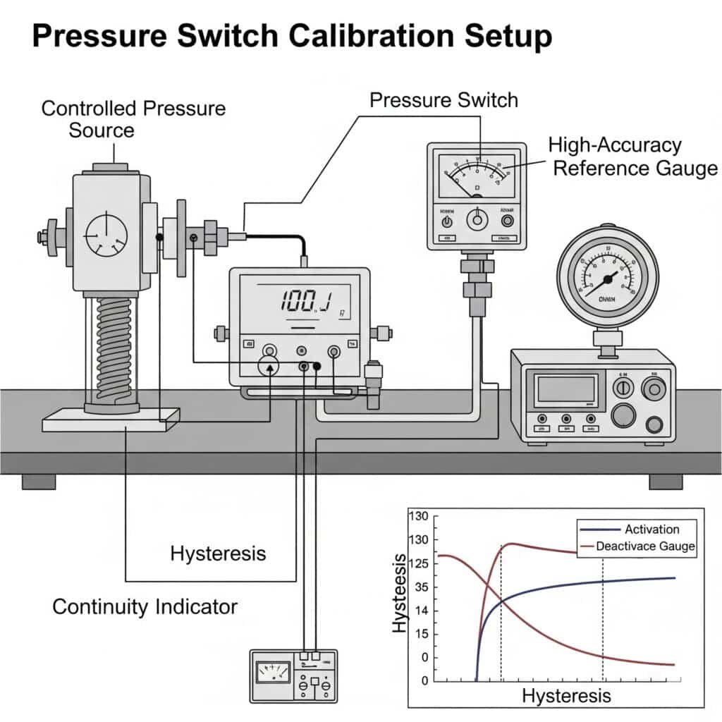
最大限の精度と信頼性を得るための圧力スイッチの校正方法とは?
適切な圧力スイッチ較正により、正確なトリガーポイントを確保し、誤ったアラームを防止し、システムの信頼性を最大化します。
圧力スイッチの校正は、ヒステリシス効果を考慮しながら、正確な作動および非作動のセットポイントを確立します。標準的な校正手順には、制御された圧力印加、セットポイントの調整、実際の動作条件下での検証テストが含まれます。確立された校正プロトコルに従うことで、一貫した性能が保証され、センサーの寿命が延びます。
圧力スイッチの基礎を理解する
校正手順に入る前に、主要な圧力スイッチの概念を理解することが不可欠です:
圧力スイッチの主要パラメータ
- セットポイント(SP): スイッチの状態が変化する圧力値
- リセットポイント(RP): スイッチが元の状態に戻る圧力値
- ヒステリシス1: セットポイントとリセットポイントの差
- 再現性: 同じ圧力値でのスイッチングの一貫性
- 正確さ: 真の圧力値からの乖離
- デッドバンド: ヒステリシスの別称、活性化と不活性化の間の圧力差
圧力スイッチの種類と校正特性
| スイッチ・タイプ | 校正方法 | 標準精度 | ヒステリシス範囲 | ベストアプリケーション |
|---|---|---|---|---|
| メカニカル・ダイアフラム | 手動調整 | ±2-5% | 範囲の10-25% | 一般産業、コスト重視 |
| ピストン式 | 手動調整 | ±1-3% | レンジの5-15% | 高圧用途 |
| ディスプレイ付き電子式 | デジタル・プログラミング | ±0.5-2% | 0.5-10%(調整可能) | 精密アプリケーション、データモニタリング |
| スマート/IoT対応 | デジタル+リモート・キャリブレーション | ±0.25-1% | 0.1~5%(プログラム可能) | インダストリー4.02遠隔監視 |
| ベプト・デジセンス | 自動補正機能付きデジタル | ±0.2-0.5% | 0.1~10%(プログラム可能) | 重要な用途、さまざまな条件 |
標準圧力スイッチ校正手順
この包括的な校正手順に従って、正確で信頼性の高い圧力スイッチの性能を確保してください:
機材要件
- 圧力源: 必要な範囲内で安定した圧力を発生させることが可能
- 基準ゲージ: 校正されるスイッチより少なくとも4倍の精度
- 接続ハードウェア: 適切な継手とアダプター
- 文書作成ツール: 校正記録用紙またはデジタルシステム
ステップごとの校正プロセス
準備段階
- スイッチを周囲温度に慣らす(最低1時間)
- リファレンスゲージの校正が最新であることを確認する
- スイッチに物理的な損傷や汚染がないか点検する
- 変更する前に初期設定を文書化する
- システムの圧力をすべて開放する最初の検証
- スイッチを校正システムに接続する
- 現在の設定値にゆっくりと圧力を加える
- 実際のスイッチング圧力を記録する
- リセットポイントまでゆっくりと圧力を下げる
- 実際のリセット圧を記録する
- 実際のヒステリシスを計算する
- 再現性を確認するために3回繰り返す調整手順
- 機械式スイッチの場合:
- 調整カバー/ロックを外す
- メーカーの指示に従い、セットポイント機構を調整
- ロックナットを締めるか、調整機構を固定する
- 電子スイッチ用:
- プログラミングモードに入る
- 希望のセットポイントとヒステリシス/リセット値を入力
- 設定を保存してプログラミングモードを終了する検証テスト
- 最初の検証手順を繰り返す
- 設定値が許容範囲内であることを確認する
- リセットポイント/ヒステリシスが要求される許容範囲内であることを確認する。
- 再現性を確認するために最低5サイクルを実施する。
- 最終設定とテスト結果を文書化システムのインストール
- 実際のアプリケーションにスイッチを取り付ける
- 通常の動作条件下で機能テストを行う
- 可能であれば、プロセスの極限でスイッチの動作を確認する
- 最終的な設置パラメータを文書化する
校正頻度と文書化
定期的な校正スケジュールを立てる:
- メーカー推奨: 通常6~12カ月
- アプリケーションの重要性: セーフティ・クリティカルなアプリケーションの頻度が高い
- 環境条件: 過酷な環境での使用頻度が高い
- 規制要件: 業界固有の基準に従う
- 過去の実績: 前回の校正で観察されたドリフトに基づいて調整する
以下を含む詳細な校正記録を保持する:
- 日付と技術者情報
- 発見時と放置時の設定
- 使用した基準機器とその校正状況
- 校正時の環境条件
- 観察された異常または懸念事項
- 次回校正予定日
様々なアプリケーションのためのヒステリシス最適化
ヒステリシスを適切に設定することは、アプリケーションの性能にとって非常に重要です:
| アプリケーション・タイプ | 推奨ヒステリシス | 推論 |
|---|---|---|
| 精密圧力制御 | 0.5~2%の範囲 | 圧力変動を最小限に抑える |
| 一般的なオートメーション | レンジの3-10% | 急激なサイクリングを防ぐ |
| コンプレッサーコントロール | レンジの10-20% | スタート/ストップの頻度を低減 |
| アラーム監視 | レンジの5-15% | 迷惑なアラームを防ぐ |
| 脈動システム | 範囲の15-25% | 通常の変動に対応 |
一般的な校正の課題と解決策
| チャレンジ | 考えられる原因 | ソリューション |
|---|---|---|
| 一貫性のないスイッチング | 振動、圧力脈動 | ヒステリシスを増やし、ダンパーを加える |
| 経時変化 | 温度変化、機械的摩耗 | より頻繁な校正、電子スイッチへのアップグレード |
| 必要な設定値を達成できない | 調整範囲外 | 適切なレンジスイッチに交換する |
| 過度のヒステリシス | 機械的摩擦、設計上の制限 | ヒステリシスを調整できる電子スイッチにアップグレード |
| 再現性の低さ | 汚染、機械的摩耗 | スイッチの清掃または交換、ろ過装置の追加 |
ケーススタディ圧力スイッチ校正の最適化
私は最近、ニュージャージー州のある製薬工場と仕事をした。その工場では、重要なプロセスラインを監視する圧力スイッチから断続的な誤報が発生していた。既存の校正手順は一貫性がなく、文書化も不十分でした。
アプリケーションを分析した結果
- 必要設定点精度:±1%
- 作動圧力:5.5 bar
- 周囲温度の変動18-27°C
- 往復運動する機器から発生する圧力脈動
私たちは包括的なソリューションを導入した:
- Beptoデジセンス電子圧力スイッチにアップグレード
- 温度補正を伴う標準化された校正手順を開発
- 8%に最適化されたヒステリシス設定で圧力の脈動に対応
- 四半期ごとの検証と年1回のフルキャリブレーションを実施
- デジタル・ドキュメンテーション・システムの構築
結果は有意であった:
- 98%により誤報が減少
- 校正時間が1スイッチあたり45分から15分に短縮
- ドキュメンテーション・コンプライアンスを100%に改善
- プロセスの信頼性が大幅に向上
- ダウンタイムの削減により、年間約$4万5,000ドルを節約
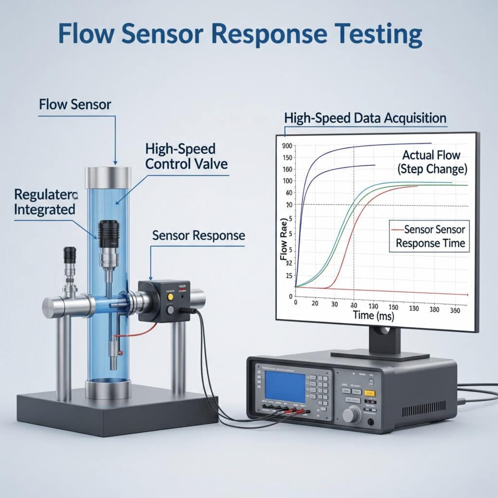
クリティカルなアプリケーションでフローセンサの応答時間を正確にテストするには?
流量センサーの応答時間は、特に安全システムや高速プロセスなど、流れの変化を迅速に検出する必要があるアプリケーションにとって非常に重要です。
流量センサーの応答時間は、センサーが流量条件の変化をいかに迅速に検知し、信号を発するかを測定する。標準的なテストでは、高速データ収集装置でセンサー出力を監視しながら、制御された段階的な流量変化を作成します。応答特性を理解することで、センサーがシステムの損傷が発生する前に重要なイベントを検出できるようになります。
流量センサーの応答ダイナミクスを理解する
流量センサーの応答時間には、いくつかの異なる要素が含まれる:
主要な応答時間パラメータ
- デッドタイム(T₀): センサーの反応が始まるまでの初期遅延
- 立ち上がり時間(T₁₀₉₀): 最終値の10%から90%までの上昇時間
- セトリング時間 (T↪Lm_209B): 最終値の±2%以内に到達するまでの時間
- 応答時間(T₉₀): 最終値の90%に達するまでの時間(最も一般的に指定されるもの)
- オーバーシュート: 最大値が最終安定値を超えた
- 回復には時間がかかる: フローが初期状態に戻った後、正常に戻るまでの時間
流量センサーの応答時間試験方法
流量センサーの応答を適切にテストするには、専門的な装置と手順が必要です:
試験装置の要件
- フロー・ジェネレーター: 迅速で再現性のあるステップチェンジが可能。
- 基準センサー: 被検査センサーの5倍以上の応答速度
- データ収集システム: 予想される応答時間より少なくとも10倍速いサンプリング・レート
- シグナル・コンディショニング: センサー出力タイプに適合
- 分析ソフトウェア: 応答パラメータの計算が可能
標準テスト手順
試験準備
- メーカーの仕様に従ってセンサーを取り付ける
- データ収集システムに接続
- 定常状態におけるセンサーの適切な動作を確認する
- ラピッドアクションバルブまたはフローコントローラの設定
- ベースラインの流量条件を確立するステップチェンジテスト(流量増加)
- 安定した初期フローを確立する(通常はゼロまたは最小)。
- ベースライン出力を少なくとも30秒間記録する
- 流量の急激な段階的増加(バルブの開弁時間は予想応答時間の10%未満であること)
- センサー出力を高サンプリングレートで記録
- 出力が完全に安定するまで最終流量を維持する
- 統計的妥当性のために最低5回繰り返すステップチェンジテスト(流量減少)
- 最大試験値で安定した初期流量を確立する
- ベースライン出力を少なくとも30秒間記録する
- 急激な段階的流量減少
- センサー出力を高サンプリングレートで記録
- 出力が完全に安定するまで最終流量を維持する
- 統計的妥当性のために最低5回繰り返すデータ分析
- 複数のテストから平均応答パラメータを計算する
- 一貫性を評価するために標準偏差を決定する
- アプリケーションの要件と比較する
- すべての結果を文書化する
流量センサーの応答時間の比較
| センサータイプ | テクノロジー | 典型的なT₉₀応答 | ベストアプリケーション | 制限事項 |
|---|---|---|---|---|
| 熱質量流量 | 熱線/フィルム | 1~5秒 | クリーンガス、低流量 | 反応が遅く、温度に影響される |
| タービン | 機械的回転 | 50~250ミリ秒 | クリーンな液体、中流量 | 可動部品、メンテナンスが必要 |
| ボルテックス | ボルテックスシェディング | 100~500ミリ秒 | 蒸気、工業用ガス | 最低必要流量 |
| 差圧 | 圧力降下 | 100~500ミリ秒 | 汎用、経済的 | 密度変化の影響を受ける |
| 超音波 | トランジットタイム | 50~200ミリ秒 | 液体、太いパイプの洗浄 | 気泡/粒子の影響を受ける |
| コリオリ3 | 質量測定 | 100~500ミリ秒 | 高精度、マスフロー | 高価、サイズ制限 |
| ベプト・クイックセンス | 熱と圧力のハイブリッド | 30~100ミリ秒 | クリティカル・アプリケーション、漏水検知 | プレミアム価格 |
アプリケーション固有の対応要件
さまざまなアプリケーションには、特定の応答時間要件がある:
| 申し込み | 必要な応答時間 | 重要な要素 |
|---|---|---|
| 漏れ検知 | <100ミリ秒 | 早期発見により、製品の損失や安全性の問題を防ぐ |
| マシン保護 | <200ミリ秒 | 損害が発生する前に問題を検知しなければならない |
| バッチ制御 | <500ミリ秒 | 投与精度と製品品質に影響 |
| プロセス監視 | <2秒 | 一般的な傾向と監督 |
| 請求書発行/保管振替 | <1秒 | スピードよりも正確さが重要 |
応答時間の最適化技術
フローセンサーの応答時間を改善する:
センサーの選択要因
- 必要に応じて、より高速な技術を選択する
- 適切なセンサーサイズを選択する(通常、小さいセンサーの方が反応が速い)
- 直接浸漬とタップオフ設置の比較
- デジタル出力とアナログ出力の比較インストールの最適化
- センサー接続のデッドボリュームを最小化
- プロセスとセンサー間の距離を縮める
- 不必要な金具や制限をなくす
- 適切な向きと流れの方向を確認する信号処理の改善
- 高いサンプリングレートを使用する
- 適切なフィルタリングの実施
- 重要なアプリケーションの予測アルゴリズムを検討する
- ノイズ除去と応答時間のバランス
ケーススタディフロー応答時間の最適化
私は最近、ミシガン州のある自動車部品メーカーに相談した。そのメーカーは、冷却システムのテストスタンドで品質上の問題を抱えていた。既存の流量センサーでは、現場での部品故障の原因となっている短時間の流れの中断を検出できなかったのです。
分析が明らかにした:
- 既存センサーの応答時間:1.2秒
- フロー中断の時間200~400ミリ秒
- 臨界検出閾値50%フロー減少
- テストサイクル時間45秒
ベプト・クイックセンス・フローセンサーを導入することで
- 応答時間 (T₉₀):75ミリ秒
- 1 kHzサンプリングによるデジタル出力
- 最適な設置位置
- カスタム信号処理アルゴリズム
結果は印象的だった:
- 100% 100ミリ秒を超えるフロー中断の検出
- 偽陽性率 <0.1%
- テストの信頼性がシックス・シグマ・レベルまで向上
- 顧客からの保証請求が87%減少
- 年間約$28万ドルの節約
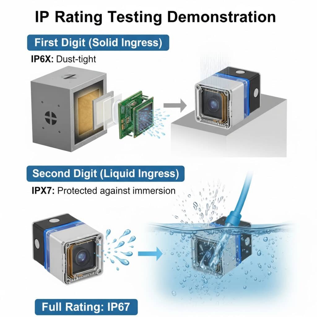
過酷な環境に対応する空気圧センサーに必要なIP保護等級は?
適切な選択 IP(侵入保護)等級4 これにより、センサーは早期に故障することなく、厳しい環境条件に耐えることができます。
IP定格は、標準化された2桁のコードを使用して、固体粒子および液体の侵入に対するセンサーの耐性を定義します。1桁目(0~6)は固形物に対する保護を示し、2桁目(0~9)は液体に対する保護を示します。IP定格を環境条件に適切に適合させることで、センサーの信頼性と寿命が劇的に向上します。
IPレーティングの基礎を理解する
IP(Ingress Protection)等級システムは、IEC規格60529で定義されており、以下の項目で構成されています:
- IPプレフィックス: 使用されている規格を示す
- 1桁目(0~6): 固形物や粉塵に対する保護
- 2桁目(0~9): 水や液体に対する保護
- オプションの文字: その他の特別な保護
総合IPレーティング参照表
| IP等級 | 強固なプロテクション | 液体保護 | 適した環境 | 代表的なアプリケーション |
|---|---|---|---|---|
| IP00 | 保護なし | 保護なし | 清潔で乾燥した室内環境 | 実験装置、内部部品 |
| IP20 | 12.5mmを超える物体から保護 | 保護なし | 基本的な室内環境 | 制御盤部品 |
| IP40 | 1mmを超える物体から保護 | 保護なし | 一般的な屋内使用 | パネルマウント・ディスプレイ、密閉式コントロール |
| IP54 | 防塵(侵入制限あり) | 水しぶきからの保護 | 軽工業、屋外保護 | 一般機械、屋外制御ボックス |
| IP65 | ダストタイト(侵入不可) | ウォータージェットからの保護 | 洗浄エリア、屋外露出 | 食品加工機器、屋外センサー |
| IP66 | ダストタイト(侵入不可) | 強力な噴流水からの保護 | 高圧洗浄 | 重工業用機器、船舶用機器 |
| IP67 | ダストタイト(侵入不可) | 一時的な浸水に対する保護(1m、30分まで) | 時々水没、激しい洗浄 | 水中ポンプ、洗浄環境 |
| IP68 | ダストタイト(侵入不可) | 連続浸漬に対する保護(1m以上、メーカー指定) | 連続水没 | 水中機器、水中センサー |
| IP69K5 | ダストタイト(侵入不可) | 高温、高圧のウォッシュダウンに対応 | スチーム洗浄、アグレッシブ洗浄 | 食品加工、製薬、酪農 |
一桁目固体粒子保護
| レベル | 保護 | 試験方法 | 有効な対策 |
|---|---|---|---|
| 0 | 保護なし | なし | 保護なし |
| 1 | 50mmを超えるもの | 50mmプローブ | 体の大きな部分(手) |
| 2 | 12.5mmを超えるもの | 12.5mmプローブ | 指 |
| 3 | 2.5mmを超えるもの | 2.5mmプローブ | 工具、太いワイヤー |
| 4 | 1mmを超えるもの | 1mmプローブ | ほとんどのワイヤー、ネジ |
| 5 | 防塵 | ダストチャンバー試験 | 粉塵(限定的な侵入を許可) |
| 6 | ほこりがたまりにくい | ダストチャンバー試験 | ほこり(侵入なし) |
2桁目液体浸入保護
| レベル | 保護 | 試験方法 | 有効な対策 |
|---|---|---|---|
| 0 | 保護なし | なし | 保護なし |
| 1 | 滴る水 | 滴水テスト | 結露、軽い水滴 |
| 2 | 水滴(15°傾けた状態) | 15°傾斜テスト | 傾けると水滴が垂れる |
| 3 | 散水 | スプレーテスト | 雨、スプリンクラー |
| 4 | 水しぶき | スプラッシュテスト | あらゆる方向からの飛沫 |
| 5 | ウォータージェット | 6.3mmノズルテスト | 低圧洗浄 |
| 6 | 強力なウォータージェット | 12.5mmノズルテスト | 激しい海、強力な洗濯 |
| 7 | 一時的な浸漬 | 1m浸漬で30分 | 一時的な洪水 |
| 8 | 連続浸漬 | メーカー指定 | 連続水没 |
| 9K | 高温高圧ジェット | 80℃、8-10MPa、10-15cm | スチーム洗浄、高圧洗浄 |
業界固有のIP定格要件
さまざまな産業には、適切な保護を必要とする特有の環境課題がある:
食品・飲料加工
- 典型的な要件: IP65からIP69K
- 環境問題への挑戦:
- 化学薬品による頻繁な洗浄
- 高圧温水洗浄
- 食品粒子汚染の可能性
- 温度変動 - 最低限を推奨する: 一般エリア用IP66、直接ウォッシュダウンゾーン用IP69K
屋外および重工業
- 典型的な要件: IP65からIP67
- 環境問題への挑戦:
- 気象条件にさらされる
- 粉塵と浮遊粒子
- 時折、水にさらされる
- 極端な気温 - 最低限を推奨する: 保護構造IP65、露出構造IP67
自動車製造
- 典型的な要件: IP54からIP67
- 環境問題への挑戦:
- オイルと冷却水の暴露
- 金属片と粉塵
- 溶接スパッタ
- 洗浄工程 - 最低限を推奨する: 一般エリア用IP65、クーラント露出エリア用IP67
化学処理
- 典型的な要件: IP65からIP68
- 環境問題への挑戦:
- 腐食性化学物質への暴露
- ウォッシュダウンの要件
- 爆発の可能性のある雰囲気
- 高湿度 - 最低限を推奨する: 適切な耐薬品性を備えたIP66
IP規格を超えるセンサー保護
IP定格は侵入保護に対応しているが、その他の環境要因も考慮する必要がある:
耐薬品性
- ハウジング材料とプロセス化学物質との適合性を確認する
- 化学環境用にはPTFE、PVDF、ステンレス鋼を検討
- ガスケットとシール材の評価
温度に関する考察
- 動作温度と保管温度の範囲を確認する
- 熱サイクル効果を考慮する
- 断熱や冷房の必要性を評価する
振動と機械的保護
- 振動と衝撃の仕様を確認する
- 振動を減衰させるための取り付けオプションを検討する
- ケーブルのストレインリリーフと保護の評価
電磁波保護
- EMC/EMIイミュニティ定格の検証
- シールドケーブルと適切なアースを考慮する
- 追加電気保護の必要性を評価する
ケーススタディIPレーティング選定の成功
私は最近、CIPシステムでセンサーの故障が頻発しているカリフォルニアの乳製品加工工場と仕事をした。IP65の既存のセンサーは2~3ヶ月使用すると故障していました。
分析が明らかにした:
- 85℃の苛性溶液で毎日洗浄
- 週1回の酸洗浄サイクル
- 手動洗浄時の高圧スプレー
- 5℃~40℃の周囲温度サイクル
ベプト・ハイジセンス・センサーの導入により:
- 高温・高圧保護等級 IP69K
- 316Lステンレス鋼ハウジング
- 化学的適合性のためのEPDMシール
- 工場で密閉されたケーブル接続
結果は有意であった:
- 18ヶ月以上の運用でセンサーの故障はゼロ
- 85%によるメンテナンスコストの削減
- システムの信頼性が99.8%に向上
- 生産稼働時間が3%増加
- 年間約$67,000の節約
環境別IP等級選択ガイド
| 環境 | 最低推奨IP定格 | 主な検討事項 |
|---|---|---|
| 屋内、管理された環境 | IP40 | 防塵、時々清掃 |
| 一般産業用屋内 | IP54 | 粉塵、時々水濡れ |
| 機械工場、軽工業 | IP65 | クーラント、洗浄、金属片 |
| 屋外、保護 | IP65 | 雨、ほこり、気温の変化 |
| 屋外、露出 | IP66/IP67 | 直接天候にさらされる、水没の可能性 |
| ウォッシュダウン環境 | IP66からIP69K | 洗浄剤、圧力、温度 |
| 水中アプリケーション | IP68 | 連続的な水への暴露、圧力 |
| 食品加工 | IP69K | 衛生、化学薬品、高温洗浄 |
結論
適切な空気圧センサーを選択するには、圧力スイッチの校正手順、フローセンサーの応答時間試験方法、および特定の環境に適した IP 保護等級を理解する必要があります。これらの原則を適用することで、システム性能を最適化し、メンテナンスコストを削減し、どのような用途においても空気圧機器の信頼性の高い動作を保証することができます。
空気圧センサーの選択に関するFAQ
一般的な産業環境では、圧力スイッチはどのくらいの頻度で校正する必要がありますか?
一般的な産業環境では、圧力スイッチは6~12ヶ月ごとに校正する必要があります。ただし、重要な用途、過酷な環境、または以前の校正でドリフトが観察された場合は、この頻度を増やす必要があります。規制産業によっては、特定の要件がある場合があります。メーカーの推奨と特定の動作条件に基づいて校正スケジュールを確立し、過去の性能データに基づいて調整します。
流量センサーの応答時間には、センサー技術以外にどのような要因が影響するのでしょうか?
センサー技術だけでなく、流量センサーの応答時間は、設置要因(配管径、センサー位置、流れの外乱からの距離)、媒体特性(粘度、密度、温度)、信号処理(フィルタリング、サンプリングレート、平均化)、および環境条件(温度変動、振動)によって影響を受ける。さらに、測定される流量変化の大きさは、知覚される応答時間に影響を与えます。
筐体のような保護を追加した場合、IP定格の低いセンサーを使用できますか?
エンクロージャ自体が環境要件を満たし、適切に設置されていれば、適切なエンクロージャ内でより低いIP定格のセンサを使用することは可能です。ただし、この方法では、エンクロージャのシールやケーブルの入口で潜在的な故障が発生する可能性があります。メンテナンスのためのアクセシビリティの必要性、筐体内の潜在的な結露の問題、および放熱要件を考慮してください。クリティカルなアプリケーションでは、適切なネイティブIP定格のセンサーを使用する方が一般的に信頼性が高い。
圧力スイッチのヒステリシスは、空気圧システムの性能にどのような影響を与えますか?
圧力スイッチのヒステリシスは、作動ポイントと非作動ポイントの間にバッファを作り、圧力がセットポイント付近で変動する際の急激なサイクルを防ぎます。ヒステリシスが小さすぎると、「チャタリング」(急速なオン/オフサイクル)を引き起こし、スイッチと接続された機器の両方を損傷させ、不安定なシステム性能を生み出します。ヒステリシスが大きすぎると、システム内の圧力変動が過大になります。最適なヒステリシス設定は、特定のアプリケーション要件に基づいて、安定性と圧力制御精度のバランスを取ります。
IP67とIP68の違いは何ですか?また、どちらが必要かを知るにはどうすればよいですか?
IP67とIP68は、どちらも塵埃の浸入に対する完全な保護を提供しますが、水の保護については異なります:IP67は一時的な浸水(水深1mで最大30分)に対して保護され、IP68はメーカーが指定する水深と時間での継続的な浸水に対して保護されます。時折、短時間の水没が発生するような用途にはIP67をお選びください。連続的に水没しても確実に動作しなければならない場合はIP68を選択する。アプリケーションで水没深度と時間が指定されている場合は、これらの要件をメーカーのIP68仕様に合わせてください。
流量センサーが私のアプリケーションに十分な速さで反応しているかどうかは、どのように確認できますか?
流量センサーの応答時間が適切かどうかを確認するには、センサーが指定する T₉ ₀応答時間(最終値の 90% に達するまでの時間)をアプリケーションのクリティカルタイムウィンドウと比較します。正確な検証のためには、高速データ収集システム(予想応答時間より少なくとも10倍速いサンプリング)と急速作動バルブを使用して、ステップ変化試験を実施してください。センサー出力を記録しながら、アプリケーションと同様の急激な流量変化を発生させます。応答曲線を分析して実際の応答パラメータを計算し、アプリケーション要件と比較します。
-
センサーと制御システムの文脈におけるヒステリシスの明確な定義を提供し、特定の入力点における出力が、その点が増加入力で近づいたか減少入力で近づいたかに依存する現象であると説明する。 ↩
-
モノのインターネット(IoT)、クラウドコンピューティング、AIといった最新のスマートテクノロジーを駆使して、従来の製造業や産業慣行を自動化することを指す。 ↩
-
コリオリ式流量計の動作原理を説明。コリオリ式流量計は、流体が通過するチューブを振動させ、その結果生じるねじれを測定することで、コリオリ効果を利用して質量流量を直接測定する。 ↩
-
国際規格IEC 60529の詳細。この規格は、侵入、ほこり、偶発的な接触、水に対する機械的ケーシングと電気的エンクロージャの保護等級を分類している。 ↩
-
ISO 20653およびDIN 40050-9規格で規定された最高レベルの保護等級であり、高圧・高温の洗浄に対する保護を意味するIP69K等級に関する具体的な情報を提供します。 ↩
