
When pneumatic systems suddenly lose efficiency and cylinders move sluggishly, engineers often overlook one critical culprit: choked flow. This phenomenon silently throttles your system’s performance, leading to costly downtime and frustrated operators. Without proper understanding, what should be a smooth operation becomes an expensive headache.
Choked flow in pneumatic systems occurs when air velocity reaches sonic speed (Mach 11) at the narrowest point of a flow restriction, creating a flow rate ceiling that cannot be exceeded regardless of upstream pressure increases. This limitation fundamentally caps your system’s performance potential.
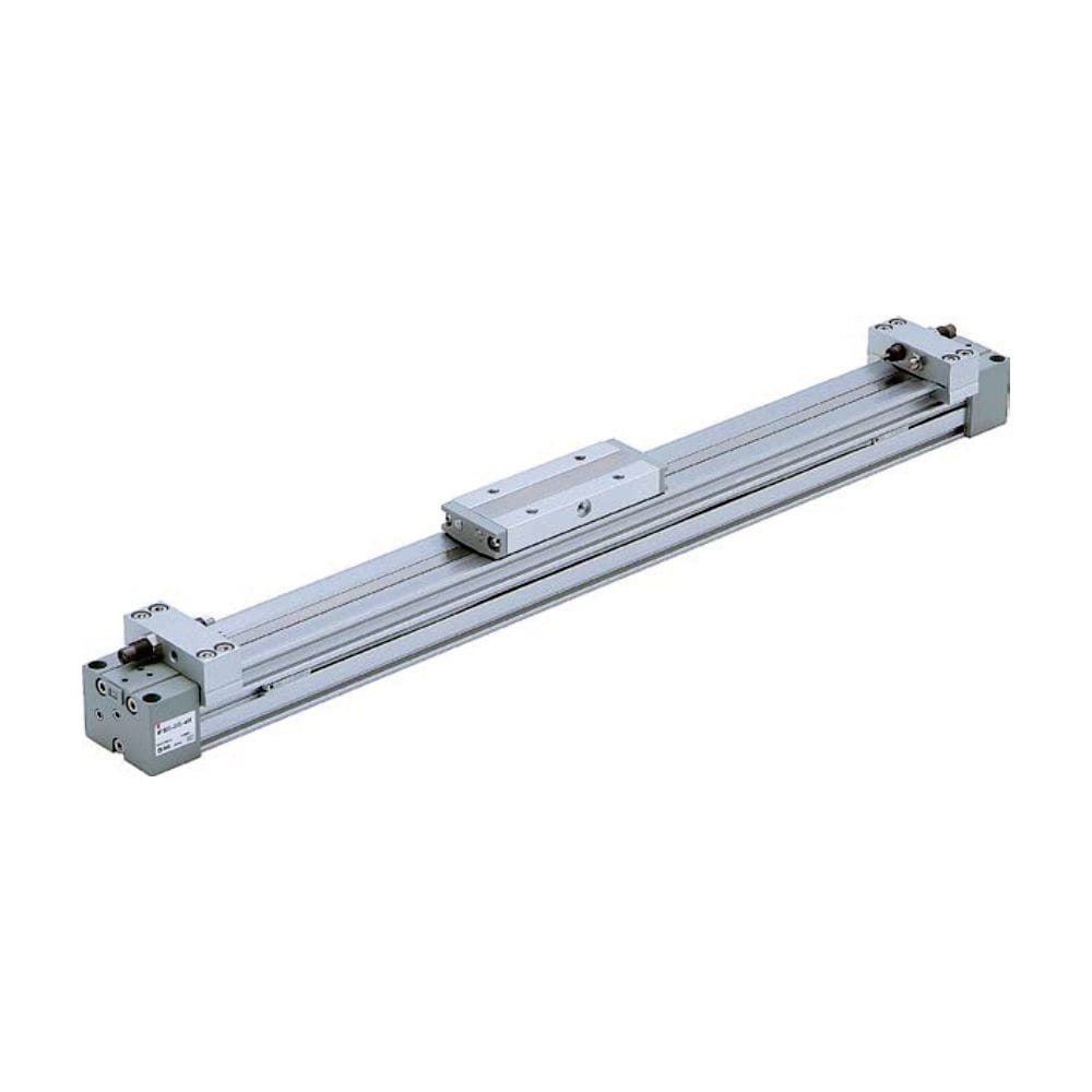
As a Sales Director at Bepto Pneumatics, I’ve witnessed countless engineers struggle with mysterious performance drops in their ロッドレスシリンダー2 applications. Just last month, a senior maintenance engineer named Robert from a Michigan automotive plant contacted us, baffled by his production line’s sudden 40% speed reduction. The answer? Choked flow conditions that nobody had diagnosed properly.
目次
- What Exactly Is Choked Flow in Pneumatic Applications?
- How Do You Identify Choked Flow Symptoms in Your System?
- What Are the Primary Causes of Choked Flow Conditions?
- How Can You Prevent and Resolve Choked Flow Issues?
What Exactly Is Choked Flow in Pneumatic Applications?
Understanding choked flow requires grasping the physics behind high-speed air movement through restrictions.
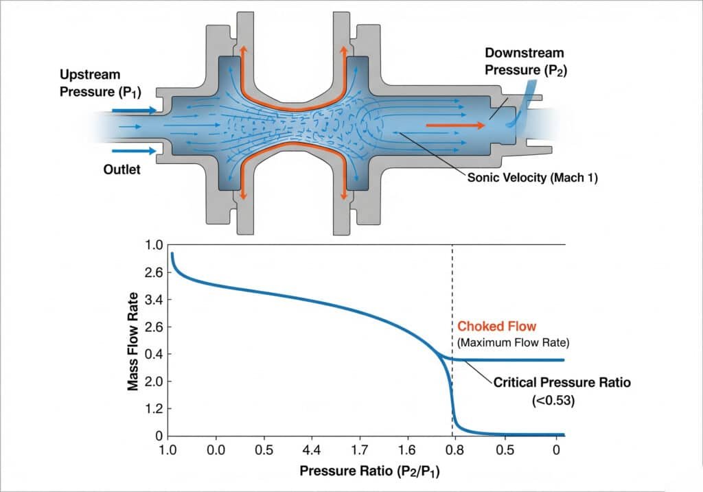
Choked flow represents the maximum mass flow rate achievable through any given orifice or restriction when downstream pressure drops below approximately 53% of upstream pressure, causing air velocity to reach sonic speed at the restriction point.
The Physics Behind Sonic Velocity
When compressed air accelerates through a narrowing passage, its velocity increases while pressure decreases. Once the air reaches sonic velocity (approximately 1,125 feet per second at room temperature), further pressure drops downstream cannot increase flow rate. This creates the “choked” condition.
臨界圧力比
The magic number in pneumatic systems is 0.528 – the critical pressure ratio3. When downstream pressure falls below 52.8% of upstream pressure, choked flow occurs regardless of how much lower the downstream pressure drops.
| コンディション | Upstream Pressure | Downstream Pressure | Flow Status |
|---|---|---|---|
| Normal Flow | 100 PSI | 60 PSI | Subsonic, variable |
| Critical Point | 100 PSI | 53 PSI | Sonic velocity reached |
| チョークド・フロー | 100 PSI | 30 PSI | Maximum flow, sonic |
How Do You Identify Choked Flow Symptoms in Your System?
Recognizing choked flow symptoms early prevents costly production delays and equipment damage.
Key indicators include: cylinders moving slower than expected despite adequate supply pressure, unusual hissing sounds from exhaust ports, inconsistent cycle times, and flow rates that don’t increase with higher supply pressure.
Performance Indicators
The most obvious symptom is when increasing supply pressure fails to improve cylinder speed. If your rodless cylinder operates at the same speed whether supplied with 80 PSI or 120 PSI, you’re likely experiencing choked flow conditions.
アコースティック・サイン
Choked flow produces distinctive high-pitched whistling or hissing sounds, particularly noticeable at exhaust ports and quick-disconnect fittings. These sounds indicate air reaching sonic velocities.
What Are the Primary Causes of Choked Flow Conditions?
Multiple factors contribute to choked flow, often working in combination to restrict system performance.
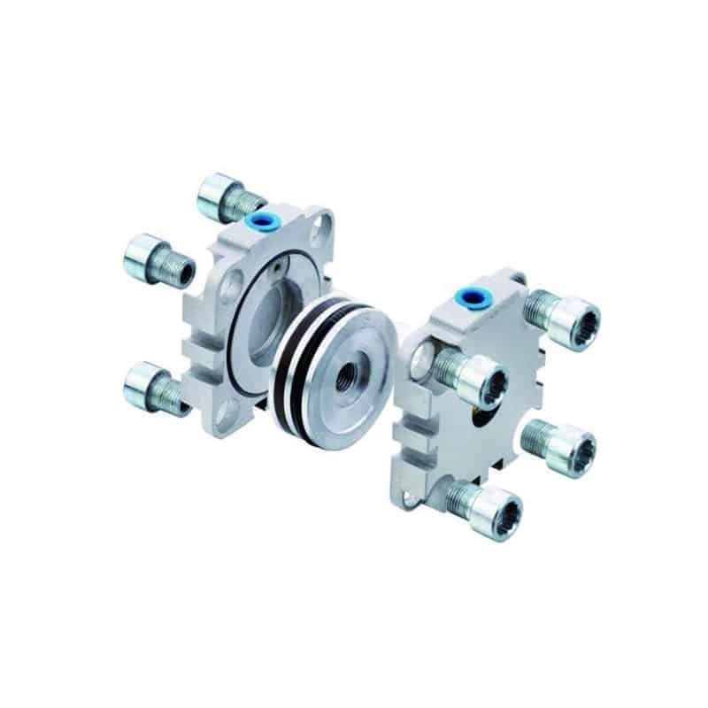
The most common causes include undersized fittings and tubing, contaminated or worn valve seats, excessive 背圧4 from restrictive exhaust systems, and improperly sized flow control valves that create unnecessary restrictions.
Component Sizing Issues
I remember helping Maria, who runs a packaging machinery company in Stuttgart, Germany. Her new production line consistently underperformed despite using premium components. The culprit? 1/4″ fittings on a system designed for 3/8″ flow rates. By upgrading to properly sized Bepto quick-connects, her cycle times improved by 35%.
システム設計要因
| コンポーネント | Undersized Impact | Proper Sizing Benefit |
|---|---|---|
| Supply Tubing | Creates bottleneck | Maintains pressure |
| Exhaust Fittings | Causes back pressure | Enables free flow |
| Valve Ports | Limits flow capacity | Maximizes performance |
Maintenance-Related Causes
Contamination, worn seals, and damaged valve seats gradually reduce effective orifice sizes, eventually triggering choked flow conditions even in properly designed systems.
How Can You Prevent and Resolve Choked Flow Issues?
Effective choked flow management combines proper system design with proactive maintenance strategies.
Prevention strategies include: selecting appropriately sized components for maximum flow rates, maintaining pressure ratios above critical thresholds, implementing regular maintenance schedules, and using high-quality replacement parts that maintain original flow characteristics.
Design Solutions
The most effective approach involves sizing all components – tubing, fittings, valves, and ports – for the maximum required flow rate rather than average operating conditions. This provides safety margin against choked flow conditions.
メンテナンスのベストプラクティス
Regular inspection and replacement of wear components prevents gradual restriction buildup. At Bepto, our replacement cylinders maintain OEM flow characteristics while offering superior durability and faster delivery times.
コンポーネントの選択基準
Choose components with flow coefficients (Cv values)5 appropriate for your maximum flow requirements. When replacing OEM parts, ensure alternatives maintain or exceed original flow specifications.
結論
Understanding and managing choked flow transforms pneumatic system performance from frustrating limitations to predictable, optimized operations that maximize productivity and minimize downtime costs. 🎯
FAQs About Choked Flow in Pneumatic Systems
Q: At what pressure ratio does choked flow occur in pneumatic systems?
A: Choked flow occurs when downstream pressure drops below 52.8% of upstream pressure, creating sonic velocity conditions that limit maximum flow rate regardless of further pressure reductions.
Q: Can choked flow damage pneumatic components?
A: While choked flow itself doesn’t directly damage components, the associated high velocities and pressure fluctuations can accelerate wear in valve seats, seals, and fittings over time.
Q: How do I calculate if my system will experience choked flow?
A: Compare your system’s pressure drop across restrictions to the critical ratio of 0.528. If downstream pressure divided by upstream pressure is less than 0.528, choked flow conditions exist.
Q: What’s the difference between choked flow and pressure drop?
A: Pressure drop is the reduction in pressure due to friction and restrictions, while choked flow is the specific condition where air velocity reaches sonic speed, creating a flow rate ceiling.
Q: Can larger tubing eliminate choked flow problems?
A: Larger tubing reduces pressure drops and can help maintain pressure ratios above critical thresholds, but the smallest restriction in your system will ultimately determine choked flow potential.
-
Learn about the Mach number and its significance as a dimensionless quantity in fluid dynamics representing the ratio of flow velocity past a boundary to the local speed of sound. ↩
-
Discover the design, types, and advantages of rodless cylinders in industrial automation applications. ↩
-
Explore the thermodynamic principles and derivation of the critical pressure ratio for compressible flow. ↩
-
Understand the causes of back pressure in pneumatic systems and its negative impact on performance and efficiency. ↩
-
Learn how the Flow Coefficient (Cv) is used to measure and compare the flow capacity of pneumatic and hydraulic valves. ↩
