
| Bore(mm) | 12 | 16 | 20 | 25 | 32 | 40 | 50 | 63 | 80 | 100 | |
| Working Medium | Air | ||||||||||
| Motion Pattern | Double-action | ||||||||||
| Ensured Pressure Resistance | 1.5Mpa(15.3kgf/cm2) | ||||||||||
| Max.Operating pressure | 1.0Mpa(10.2kgf/cm2) | ||||||||||
| Min. Operating pressure | 0.12Mpa(1.2kgf/cm2) | ||||||||||
| Ambient and Medium Temperature | -10~+60℃ | ||||||||||
| Piston Speed | 50~500mm/s | 50~400mm/s | |||||||||
| Buffer | Rubber Cushion | ||||||||||
| Tolerance of Stroke | +1.5 0 mm |
||||||||||
| Bearing | (Slide bearing/ball guide bdaring) | ||||||||||
| Precision of Piston rod Non-rotating |
Slide Bearing | ±0.08° | ±0.07° | ±0.06° | ±0.05° | ±0.04° | |||||
| Ball Guide Bearing | ±0.10° | ±0.09° | ±0.08° | ±0.06 | ±0.05° | ||||||
| Port size | M5×0.8 | G1/8″ | G1/4″ | G3/8″ | |||||||
| Bore size(mm) | Standard stroke(mm) |
| 12, 16 | 10 20 30 40 50 75 100 125 150 175 200 250 |
| 20, 25 | 20 30 40 50 75 100 125 150 175 200 250 300 350 400 |
| 32 to 100 | 25 50 75 100 125 150 175 200 250 300 350 400 |
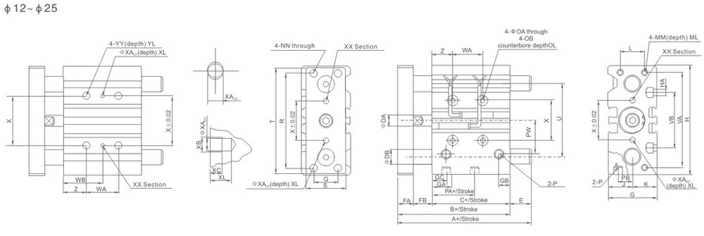
| Bore size | Standard stroke (mm) | B | C | DA | FA | FB | G | GA | GB | H | HA | J | K | L | MM | ML | NN | OA |
| 12 | 10 20 30 40 50 75 100 | 42 | 29 | 6 | 8 | 5 | 26 | 11 | 7.5 | 58 | M4 | 13 | 13 | 18 | M4×0.7 | 10 | M4×0.7 | 4.3 |
| 16 | 46 | 33 | 8 | 8 | 5 | 30 | 11 | 8 | 64 | M4 | 15 | 15 | 22 | M5×0.8 | 12 | M5×0.8 | 4.3 | |
| 20 | 20 30 40 50 75 100 125 150 175 200 | 53 | 37 | 10 | 10 | 6 | 36 | 10.5 | 8.5 | 83 | M5 | 18 | 18 | 24 | M5×0.8 | 13 | M5×0.8 | 5.6 |
| 25 | 53.5 | 37.5 | 12 | 10 | 6 | 42 | 11.5 | 9 | 93 | M5 | 21 | 21 | 30 | M6×1.0 | 15 | M6×1.0 | 5.6 |
| Bore size | Standard stroke (mm) | OB | OL | P | PA | PB | PW | Q | R | S | T | U | VA | VB | X | XA | XB | XC | YL | Z |
| 12 | 10 20 30 40 50 75 100 | 8 | 4.5 | M5×0.8 | 13 | 8 | 18 | 14 | 48 | 22 | 56 | 41 | 50 | 37 | 23 | 3 | 3.5 | 3 | 10 | 5 |
| 16 | 8 | 4.5 | M5×0.8 | 15 | 10 | 19 | 16 | 54 | 25 | 62 | 46 | 56 | 38 | 24 | 3 | 3.5 | 3 | 10 | 5 | |
| 20 | 20 30 40 50 75 100 125 150 175 200 | 9.5 | 5.5 | RC1/8 | 12.5 | 10.5 | 25 | 18 | 70 | 30 | 81 | 54 | 72 | 44 | 28 | 3 | 3.5 | 3 | 12 | 17 |
| 25 | 9.5 | 5.5 | RC1/8 | 12.5 | 13.5 | 28.5 | 26 | 78 | 38 | 91 | 64 | 82 | 50 | 34 | 4 | 4.5 | 3 | 12 | 17 |
| Bore size | Standard stroke (mm) | WA | WB | XL | YY | ||||
| 30 st or less | Over 40 st to 100 st | 125 st or less | 30 st or less | Over 40 st to 100 st | 125 st or less | ||||
| 12 | 10 20 30 40 50 75 100 | 20 | 40 | – | 15 | 25 | – | 6 | M5×0.8 |
| 16 | 24 | 44 | – | 17 | 27 | – | 6 | M5×0.8 | |
| 20 | 20 30 40 50 75 100 125 150 175 200 | 24 | 44 | 120 | 29 | 39 | 77 | 6 | M6×1.0 |
| 25 | 24 | 44 | 120 | 29 | 39 | 77 | 6 | M6×1.0 | |
| MGPG Slide bearing | MGPL Ball bushing bearing | |||||||||||||||||||||||||||||||||||||||||||||||||||||||||
|
|
|||||||||||||||||||||||||||||||||||||||||||||||||||||||||
| MGPM Slide bearing | MGPL Ball bushing bearing | |||||||||||||||||||||||||||||||||||||||||||||||||||||||||||||||||
|
|
|||||||||||||||||||||||||||||||||||||||||||||||||||||||||||||||||

| Bore size | Standard stroke (mm) | B | C | DA | FA | FB | G | GA | GB | GC | H | HA | J | K | L | MM | ML | NN | OA | OB | OL | P | PA | PB | PW | Q |
| 32 | 25,50, 70, 100,125, 150,175, 200 |
59.5 | 37.5 | 16 | 12 | 10 | 48 | 12.5 | 9 | 12.5 | 112 | M6 | 24 | 24 | 34 | M8×1.25 | 20 | M8×1.25 | 6.6 | 11 | 7.5 | RC1/8 | 7 | 15 | 34 | 30 |
| 40 | 66 | 44 | 16 | 12 | 10 | 54 | 14 | 10 | 14 | 120 | M6 | 27 | 27 | 40 | M8×1.25 | 20 | M8×1.25 | 6.6 | 11 | 7.5 | RC1/8 | 13 | 18 | 38 | 30 | |
| 50 | 72 | 44 | 20 | 16 | 12 | 64 | 14 | 11 | 12 | 148 | M8 | 32 | 32 | 46 | M10×1.5 | 22 | M10×1.5 | 8.6 | 14 | 9 | RC1/4 | 9 | 21.5 | 47 | 40 | |
| 63 | 77 | 49 | 20 | 16 | 12 | 78 | 16.5 | 13.5 | 16.5 | 162 | M10 | 39 | 39 | 58 | M10×1.5 | 22 | M10×1.5 | 8.6 | 14 | 9 | RC1/4 | 14 | 28 | 55 | 50 |
| R | S | T | U | VA | VB | X | XA | XB | XC | XL | Z |
| 96 | 44 | 110 | 78 | 98 | 63 | 42 | 4 | 4.5 | 3 | 6 | 21 |
| 104 | 44 | 118 | 85 | 106 | 72 | 50 | 4 | 4.5 | 3 | 6 | 22 |
| 130 | 60 | 146 | 110 | 130 | 92 | 66 | 5 | 6 | 4 | 8 | 24 |
| 130 | 70 | 158 | 124 | 142 | 110 | 80 | 5 | 6 | 4 | 8 | 24 |
| MGPM Slide bearing | |||||||
| Bore size | A | DB | E | ||||
| 50st≥ | 50st<200st≥ | 200st< | 50st≥ | 50st<200st≥ | 200st< | ||
| 32 | 97 | 102 | 140 | 20 | 37.5 | 42.5 | 80.5 |
| 40 | 97 | 102 | 140 | 20 | 31 | 36 | 74 |
| 50 | 106.5 | 118 | 161 | 25 | 34.5 | 46 | 89 |
| 63 | 106.5 | 118 | 161 | 25 | 29.5 | 41 | 84 |
| MGPL Ball bushing bearing | |||||||||
| Bore size | A | DB | E | ||||||
| 50st≥ | 50st<100st≥ | 100st<200st≥ | 200st< | 50st≥ | 50st<100st≥ | 100st<200st≥ | 200st< | ||
| 32 | 81 | 98 | 118 | 140 | 16 | 21.5 | 38.5 | 58.5 | 80 |
| 40 | 81 | 98 | 118 | 140 | 16 | 15 | 32 | 52 | 74 |
| 50 | 93 | 114 | 134 | 161 | 20 | 21 | 42 | 62 | 89 |
| 63 | 93 | 114 | 134 | 161 | 20 | 16 | 37 | 57 | 84 |

| Bore size | Standard stroke (mm) | B | C | DA | FA | FB | G | GA | GB | GC | H | HA | J | LA | LB | K | L | MM | ML | NN | OA | OB | OL | P | PA | PB |
| 80 | 25,50,70, 100, 125,150,175,200 |
95.5 | 56.5 | 25 | 22 | 18 | 91.5 | 19 | 15.5 | 14.5 | 202 | M12 | 45.5 | 38 | 7.5 | 46 | 54 | M12×1.75 | 30 | M12×1.75 | 10.6 | 17.5 | 8 | RC3/8 | 14.5 | 25.5 |
| 100 | 116 | 66 | 30 | 25 | 111.5 | 23 | 23 | 19 | 18 | 240 | M14 | 55.5 | 45 | 10.5 | 56 | 62 | M14×2.0 | 32 | M14×2.0 | 12.5 | 20 | 8 | RC3/8 | 17.5 | 32.5 |
| Bore size | Standard stroke (mm) | PW | Q | R | S | T | U | VA | VB | WA | WB | X | XA | XB | XC | XL | YY | YL | Z | ||||
| 25st | 50,75,
100st |
100st or above | 25st | 50,75,
100st |
100st or above | ||||||||||||||||||
| 80 | 25,50,70, 100, 125,150,175,200 |
74 | 52 | 174 | 75 | 198 | 156 | 180 | 140 | 28 | 52 | 128 | 42 | 54 | 92 | 100 | 6 | 7 | 5 | 10 | M12×1.75 | 24 | 28 |
| 100 | 89 | 64 | 210 | 90 | 236 | 188 | 210 | 166 | 48 | 72 | 148 | 35 | 47 | 85 | 124 | 6 | 7 | 5 | 10 | M14×2.0 | 28 | 11 | |
| Bore size | A | DB | E | ||||
| 50st≥ | 50st<200st≥ | 200st< | 50st≥ | 50st<200st≥ | 200st< | ||
| 80 | 115 | 142 | 193 | 30 | 18.5 | 45.5 | 96.5 |
| 100 | 137 | 162 | 203 | 36 | 21 | 46 | 87 |
| Bore size | A | DB | E | ||||||
| 50st≥ | 25st<50st≥ | 50st<200st≥ | 200st< | 50st≥ | 25st<50st≥ | 50st<200st≥ | 200st< | ||
| 80 | 109.5 | 130 | 160 | 193 | 25 | 13 | 33.5 | 63.5 | 96.5 |
| 100 | 121 | 147 | 180 | 203 | 30 | 5 | 31 | 64 | 87 |
| Bore size | Standard stroke (mm) | B | C | DA | FA | FB | G | GA | GB | H | HA | J | K | L | MM | ML | NN | OA |
| 12 | 10 20 30 40 50 75 100 | 42 | 29 | 6 | 8 | 5 | 26 | 11 | 7.5 | 58 | M4 | 13 | 13 | 18 | M4×0.7 | 10 | M4×0.7 | 4.3 |
| 16 | 46 | 33 | 8 | 8 | 5 | 30 | 11 | 8 | 64 | M4 | 15 | 15 | 22 | M5×0.8 | 12 | M5×0.8 | 4.3 | |
| 20 | 20 30 40 50 75 100 125 150 175 200 | 53 | 37 | 10 | 10 | 6 | 36 | 10.5 | 8.5 | 83 | M5 | 18 | 18 | 24 | M5×0.8 | 13 | M5×0.8 | 5.6 |
| 25 | 53.5 | 37.5 | 12 | 10 | 6 | 42 | 11.5 | 9 | 93 | M5 | 21 | 21 | 30 | M6×1.0 | 15 | M6×1.0 | 5.6 |
| Bore size | Standard stroke (mm) | OB | OL | P | PA | PB | PW | Q | R | S | T | U | VA | VB | X | XA | XB | XC | YL | Z |
| 12 | 10 20 30 40 50 75 100 | 8 | 4.5 | M5×0.8 | 13 | 8 | 18 | 14 | 48 | 22 | 56 | 41 | 50 | 37 | 23 | 3 | 3.5 | 3 | 10 | 5 |
| 16 | 8 | 4.5 | M5×0.8 | 15 | 10 | 19 | 16 | 54 | 25 | 62 | 46 | 56 | 38 | 24 | 3 | 3.5 | 3 | 10 | 5 | |
| 20 | 20 30 40 50 75 100 125 150 175 200 | 9.5 | 5.5 | RC1/8 | 12.5 | 10.5 | 25 | 18 | 70 | 30 | 81 | 54 | 72 | 44 | 28 | 3 | 3.5 | 3 | 12 | 17 |
| 25 | 9.5 | 5.5 | RC1/8 | 12.5 | 13.5 | 28.5 | 26 | 78 | 38 | 91 | 64 | 82 | 50 | 34 | 4 | 4.5 | 3 | 12 | 17 |
| Bore size | Standard stroke (mm) | WA | WB | XL | YY | ||||
| 30 st or less | Over 40 st to 100 st | 125 st or less | 30 st or less | Over 40 st to 100 st | 125 st or less | ||||
| 12 | 10 20 30 40 50 75 100 | 20 | 40 | – | 15 | 25 | – | 6 | M5×0.8 |
| 16 | 24 | 44 | – | 17 | 27 | – | 6 | M5×0.8 | |
| 20 | 20 30 40 50 75 100 125 150 175 200 | 24 | 44 | 120 | 29 | 39 | 77 | 6 | M6×1.0 |
| 25 | 24 | 44 | 120 | 29 | 39 | 77 | 6 | M6×1.0 | |
| MGPG Slide bearing | MGPL Ball bushing bearing | |||||||||||||||||||||||||||||||||||||||||||||||||||||||||
|
|
|||||||||||||||||||||||||||||||||||||||||||||||||||||||||
| MGPM Slide bearing | MGPL Ball bushing bearing | |||||||||||||||||||||||||||||||||||||||||||||||||||||||||||||||||
|
|
|||||||||||||||||||||||||||||||||||||||||||||||||||||||||||||||||
| Bore size | Standard stroke (mm) | B | C | DA | FA | FB | G | GA | GB | GC | H | HA | J | K | L | MM | ML | NN | OA | OB | OL | P | PA | PB | PW | Q |
| 32 | 25,50, 70, 100,125, 150,175, 200 |
59.5 | 37.5 | 16 | 12 | 10 | 48 | 12.5 | 9 | 12.5 | 112 | M6 | 24 | 24 | 34 | M8×1.25 | 20 | M8×1.25 | 6.6 | 11 | 7.5 | RC1/8 | 7 | 15 | 34 | 30 |
| 40 | 66 | 44 | 16 | 12 | 10 | 54 | 14 | 10 | 14 | 120 | M6 | 27 | 27 | 40 | M8×1.25 | 20 | M8×1.25 | 6.6 | 11 | 7.5 | RC1/8 | 13 | 18 | 38 | 30 | |
| 50 | 72 | 44 | 20 | 16 | 12 | 64 | 14 | 11 | 12 | 148 | M8 | 32 | 32 | 46 | M10×1.5 | 22 | M10×1.5 | 8.6 | 14 | 9 | RC1/4 | 9 | 21.5 | 47 | 40 | |
| 63 | 77 | 49 | 20 | 16 | 12 | 78 | 16.5 | 13.5 | 16.5 | 162 | M10 | 39 | 39 | 58 | M10×1.5 | 22 | M10×1.5 | 8.6 | 14 | 9 | RC1/4 | 14 | 28 | 55 | 50 |
| R | S | T | U | VA | VB | X | XA | XB | XC | XL | Z |
| 96 | 44 | 110 | 78 | 98 | 63 | 42 | 4 | 4.5 | 3 | 6 | 21 |
| 104 | 44 | 118 | 85 | 106 | 72 | 50 | 4 | 4.5 | 3 | 6 | 22 |
| 130 | 60 | 146 | 110 | 130 | 92 | 66 | 5 | 6 | 4 | 8 | 24 |
| 130 | 70 | 158 | 124 | 142 | 110 | 80 | 5 | 6 | 4 | 8 | 24 |
| MGPM Slide bearing | |||||||
| Bore size | A | DB | E | ||||
| 50st≥ | 50st<200st≥ | 200st< | 50st≥ | 50st<200st≥ | 200st< | ||
| 32 | 97 | 102 | 140 | 20 | 37.5 | 42.5 | 80.5 |
| 40 | 97 | 102 | 140 | 20 | 31 | 36 | 74 |
| 50 | 106.5 | 118 | 161 | 25 | 34.5 | 46 | 89 |
| 63 | 106.5 | 118 | 161 | 25 | 29.5 | 41 | 84 |
| MGPL Ball bushing bearing | |||||||||
| Bore size | A | DB | E | ||||||
| 50st≥ | 50st<100st≥ | 100st<200st≥ | 200st< | 50st≥ | 50st<100st≥ | 100st<200st≥ | 200st< | ||
| 32 | 81 | 98 | 118 | 140 | 16 | 21.5 | 38.5 | 58.5 | 80 |
| 40 | 81 | 98 | 118 | 140 | 16 | 15 | 32 | 52 | 74 |
| 50 | 93 | 114 | 134 | 161 | 20 | 21 | 42 | 62 | 89 |
| 63 | 93 | 114 | 134 | 161 | 20 | 16 | 37 | 57 | 84 |

| Bore size | Standard stroke (mm) | B | C | DA | FA | FB | G | GA | GB | GC | H | HA | J | LA | LB | K | L | MM | ML | NN | OA | OB | OL | P | PA | PB |
| 80 | 25,50,70, 100, 125,150,175,200 |
95.5 | 56.5 | 25 | 22 | 18 | 91.5 | 19 | 15.5 | 14.5 | 202 | M12 | 45.5 | 38 | 7.5 | 46 | 54 | M12×1.75 | 30 | M12×1.75 | 10.6 | 17.5 | 8 | RC3/8 | 14.5 | 25.5 |
| 100 | 116 | 66 | 30 | 25 | 111.5 | 23 | 23 | 19 | 18 | 240 | M14 | 55.5 | 45 | 10.5 | 56 | 62 | M14×2.0 | 32 | M14×2.0 | 12.5 | 20 | 8 | RC3/8 | 17.5 | 32.5 |
| Bore size | Standard stroke (mm) | PW | Q | R | S | T | U | VA | VB | WA | WB | X | XA | XB | XC | XL | YY | YL | Z | ||||
| 25st | 50,75,
100st |
100st or above | 25st | 50,75,
100st |
100st or above | ||||||||||||||||||
| 80 | 25,50,70, 100, 125,150,175,200 |
74 | 52 | 174 | 75 | 198 | 156 | 180 | 140 | 28 | 52 | 128 | 42 | 54 | 92 | 100 | 6 | 7 | 5 | 10 | M12×1.75 | 24 | 28 |
| 100 | 89 | 64 | 210 | 90 | 236 | 188 | 210 | 166 | 48 | 72 | 148 | 35 | 47 | 85 | 124 | 6 | 7 | 5 | 10 | M14×2.0 | 28 | 11 | |
| Bore size | A | DB | E | ||||
| 50st≥ | 50st<200st≥ | 200st< | 50st≥ | 50st<200st≥ | 200st< | ||
| 80 | 115 | 142 | 193 | 30 | 18.5 | 45.5 | 96.5 |
| 100 | 137 | 162 | 203 | 36 | 21 | 46 | 87 |
| Bore size | A | DB | E | ||||||
| 50st≥ | 25st<50st≥ | 50st<200st≥ | 200st< | 50st≥ | 25st<50st≥ | 50st<200st≥ | 200st< | ||
| 80 | 109.5 | 130 | 160 | 193 | 25 | 13 | 33.5 | 63.5 | 96.5 |
| 100 | 121 | 147 | 180 | 203 | 30 | 5 | 31 | 64 | 87 |