

Vă confruntați cu opriri neașteptate ale mașinilor, performanțe inconsecvente ale sistemelor pneumatice sau defecțiuni premature ale senzorilor în medii dificile? Aceste probleme frecvente provin adesea din selectarea necorespunzătoare a senzorilor, ceea ce duce la timpi de oprire costisitori, probleme de calitate și întreținere excesivă. Alegerea senzorilor pneumatici potriviți poate rezolva imediat aceste probleme critice.
Senzorul pneumatic ideal trebuie să fie calibrat corespunzător pentru cerințele specifice de presiune ale sistemului dvs., să răspundă suficient de rapid pentru a surprinde evenimentele critice de debit și să ofere o protecție de mediu adecvată pentru condițiile dvs. de funcționare. Selectarea corectă necesită înțelegerea procedurilor de calibrare, a metodelor de testare a timpului de răspuns și a standardelor de protecție.
Îmi amintesc că anul trecut am vizitat o instalație de procesare a alimentelor din Wisconsin unde se înlocuiau presostatele la fiecare 2-3 luni din cauza deteriorării cauzate de spălare. După ce au analizat aplicația și au implementat senzori clasificați corespunzător cu protecție IP67 adecvată, frecvența înlocuirii acestora a scăzut la zero în cursul anului următor, economisind peste $32,000 în timpi morți și materiale. Permiteți-mi să vă împărtășesc ceea ce am învățat de-a lungul anilor mei în industria pneumatică.
Tabla de conținut
- Standarde și proceduri de calibrare a comutatoarelor de presiune
- Cum să testați și să verificați timpul de răspuns al senzorului de debit
- Ghid cuprinzător de clasificare IP pentru medii dificile
Cum ar trebui să calibrați comutatoarele de presiune pentru precizie și fiabilitate maxime?
Calibrarea corectă a presostatului asigură puncte de declanșare precise, previne alarmele false și maximizează fiabilitatea sistemului.
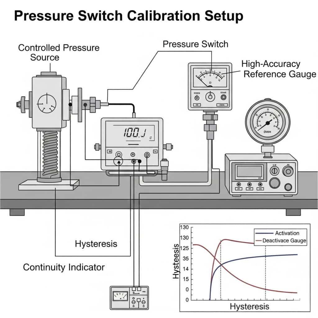
Calibrarea presostatului stabilește puncte de referință precise de activare și dezactivare, ținând cont în același timp de efectele de histerezis. Procedurile standard de calibrare implică aplicarea controlată a presiunii, ajustarea punctului de referință și testarea de verificare în condiții reale de funcționare. Respectarea protocoalelor de calibrare stabilite asigură performanțe constante și prelungește durata de viață a senzorului.
Înțelegerea principiilor de bază ale comutatoarelor de presiune
Înainte de a intra în procedurile de calibrare, este esențial să înțelegeți conceptele cheie ale presostatului:
Parametrii cheie ai comutatorului de presiune
- Punct de referință (SP): Valoarea presiunii la care comutatorul își schimbă starea
- Punct de resetare (RP): Valoarea presiunii la care comutatorul revine la starea sa inițială
- Histerezis1: Diferența dintre punctul de referință și punctul de resetare
- Repetabilitate: Consistența comutării la aceeași valoare a presiunii
- Acuratețe: Deviație de la valoarea reală a presiunii
- Banda moartă: Un alt termen pentru histerezis, diferența de presiune între activare și dezactivare
Tipuri de comutatoare de presiune și caracteristicile lor de calibrare
| Tip întrerupător | Metoda de calibrare | Acuratețe tipică | Intervalul de histerezis | Cele mai bune aplicații |
|---|---|---|---|---|
| Diafragmă mecanică | Reglare manuală | ±2-5% | 10-25% din gama | Industrie generală, sensibilă la costuri |
| Tip piston | Reglare manuală | ±1-3% | 5-15% din gamă | Aplicații cu presiune mai mare |
| Electronic cu afișaj | Programare digitală | ±0,5-2% | 0,5-10% (reglabil) | Aplicații de precizie, monitorizarea datelor |
| Inteligent/IoT-abilitat | Calibrare digitală + la distanță | ±0,25-1% | 0,1-5% (programabil) | Industria 4.02, monitorizare de la distanță |
| Bepto DigiSense | Digital cu autocompensare | ±0,2-0,5% | 0,1-10% (programabil) | Aplicații critice, condiții variate |
Procedura de calibrare a presostatului standard
Urmați această procedură completă de calibrare pentru a asigura performanțe precise și fiabile ale presostatului:
Cerințe privind echipamentele
- Sursă de presiune: Capabil să genereze o presiune stabilă în întreaga gamă necesară
- Ecartament de referință: Cel puțin de 4 ori mai precis decât comutatorul calibrat
- Hardware de conectare: Fitinguri și adaptoare corespunzătoare
- Instrumente de documentare: Formulare de înregistrare a calibrării sau sistem digital
Procesul de calibrare pas cu pas
Faza de pregătire
- Lăsați comutatorul să se aclimatizeze la temperatura ambiantă (minimum 1 oră)
- Verificați dacă calibrarea etalonului de referință este curentă
- Inspectați comutatorul pentru a depista deteriorări fizice sau contaminare
- Documentați setările inițiale înainte de a efectua modificări
- Eliberați toată presiunea din sistemVerificarea inițială
- Conectați comutatorul la sistemul de calibrare
- Aplicați încet presiunea la punctul de referință curent
- Înregistrarea presiunii reale de comutare
- Reduceți încet presiunea până la punctul de resetare
- Înregistrați presiunea reală de resetare
- Calculați histerezisul real
- Repetați de 3 ori pentru a verifica repetabilitateaProcedura de reglare
- Pentru întrerupătoare mecanice:
- Îndepărtați capacul/blocajul de reglare
- Reglați mecanismul punctului de reglare conform instrucțiunilor producătorului
- Strângeți piulița de blocare sau fixați mecanismul de reglare
- Pentru întrerupătoare electronice:
- Intrați în modul de programare
- Introduceți punctul de referință dorit și valorile de histerezis/reset
- Salvați setările și ieșiți din modul de programareTeste de verificare
- Repetați procedura de verificare inițială
- Confirmați că punctul de referință se încadrează în toleranța necesară
- Confirmați că punctul de resetare/histerezis se încadrează în toleranța necesară
- Efectuați minimum 5 cicluri pentru a verifica repetabilitatea
- Documentați setările finale și rezultatele testelorInstalarea sistemului
- Instalați comutatorul în aplicația reală
- Efectuați testul funcțional în condiții normale de funcționare
- Verificați funcționarea comutatorului la extremele procesului, dacă este posibil
- Documentați parametrii finali de instalare
Frecvența calibrării și documentația
Stabiliți un program regulat de calibrare bazat pe:
- Recomandările producătorului: De obicei 6-12 luni
- Criticitatea aplicației: Mai frecvente pentru aplicații de siguranță critice
- Condiții de mediu: Mai frecvente în medii dificile
- Cerințe de reglementare: Respectați standardele specifice industriei
- Performanță istorică: Se ajustează pe baza deviației observate la calibrările anterioare
Păstrați înregistrări detaliate de calibrare, inclusiv:
- Informații privind data și tehnicianul
- Setări ca găsit și ca lăsat
- Echipamentul de referință utilizat și starea de calibrare a acestuia
- Condiții de mediu în timpul calibrării
- Anomalii sau preocupări observate
- Următoarea dată de calibrare programată
Optimizarea histerezisului pentru diferite aplicații
Setarea corectă a histerezisului este esențială pentru performanța aplicației:
| Tip de aplicație | Histerezis recomandat | Raționament |
|---|---|---|
| Control de precizie al presiunii | 0,5-2% din gamă | Minimizează fluctuațiile de presiune |
| Automatizare generală | 3-10% din gamă | Previne ciclurile rapide |
| Controlul compresorului | 10-20% din gama | Reduce frecvența de pornire/oprire |
| Monitorizarea alarmelor | 5-15% din gamă | Previne alarmele neplăcute |
| Sisteme pulsatorii | 15-25% din gama | Acceptă fluctuațiile normale |
Provocări și soluții comune de calibrare
| Provocare | Cauze potențiale | Soluții |
|---|---|---|
| Comutare inconsecventă | Vibrații, pulsații de presiune | Creșteți histerezisul, adăugați amortizare |
| Deriva în timp | Variații de temperatură, uzură mecanică | Calibrare mai frecventă, upgrade la comutatorul electronic |
| Nu se poate atinge punctul de reglare necesar | În afara intervalului de reglare | Înlocuiți cu un comutator de gamă adecvat |
| Histerezis excesiv | Frecarea mecanică, limitări de proiectare | Treceți la comutator electronic cu histerezis reglabil |
| Repetabilitate slabă | Contaminare, uzură mecanică | Curățați sau înlocuiți comutatorul, adăugați filtrare |
Studiu de caz: Optimizarea calibrării comutatorului de presiune
Am lucrat recent cu o unitate de producție farmaceutică din New Jersey care se confrunta cu alarme false intermitente de la presostatele care monitorizau liniile de proces critice. Procedura lor de calibrare existentă era inconsecventă și slab documentată.
După analizarea aplicației lor:
- Precizia necesară a punctului de referință: ±1%
- Presiune de funcționare: 5,5 bar
- Fluctuații de temperatură ambientală: 18-27°C
- Pulsații de presiune prezente la echipamentele cu mișcare alternativă
Am implementat o soluție cuprinzătoare:
- Actualizat la presostate electronice Bepto DigiSense
- Elaborarea unei proceduri standardizate de calibrare cu compensare a temperaturii
- Setări optimizate ale histerezisului la 8% pentru a se adapta pulsațiilor de presiune
- Au fost implementate verificarea trimestrială și calibrarea anuală completă
- Crearea unui sistem de documentare digitală cu tendințe istorice
Rezultatele au fost semnificative:
- Alarmele false reduse de 98%
- Timp de calibrare redus de la 45 de minute la 15 minute pentru fiecare comutator
- Conformitatea documentației îmbunătățită la 100%
- Îmbunătățirea măsurabilă a fiabilității proceselor
- Economii anuale de aproximativ $45,000 în reducerea timpilor morți
Cum puteți testa cu exactitate timpul de răspuns al senzorului de debit pentru aplicații critice?
Timpul de răspuns al senzorului de debit este esențial pentru aplicațiile care necesită detectarea rapidă a modificărilor de debit, în special în sistemele de siguranță sau în procesele de mare viteză.
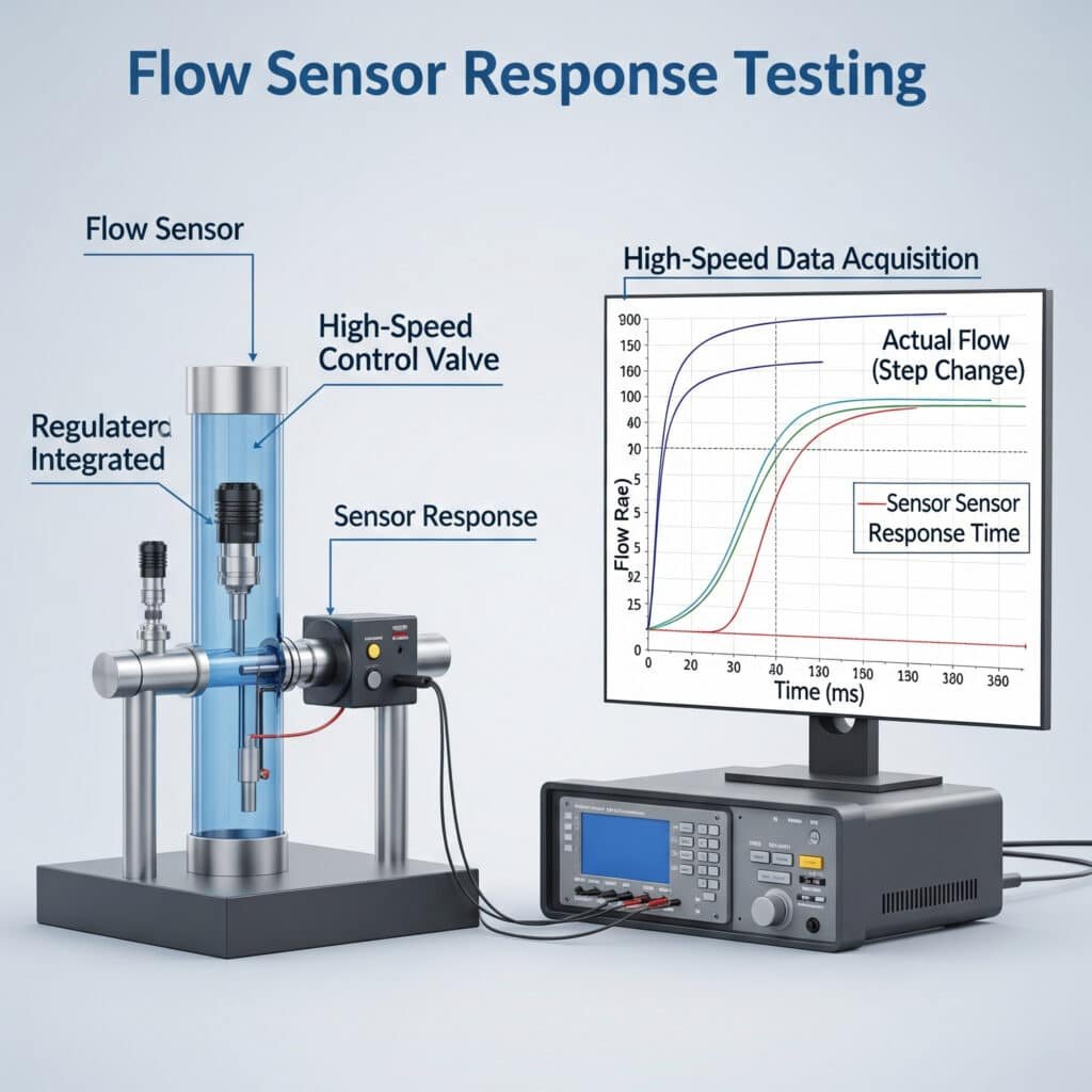
Timpul de răspuns al senzorului de debit măsoară rapiditatea cu care un senzor detectează și semnalează o modificare a condițiilor de debit. Testarea standard implică crearea unor schimbări controlate ale debitului în timp ce se monitorizează ieșirea senzorului cu un echipament de achiziție de date de mare viteză. Înțelegerea caracteristicilor de răspuns asigură faptul că senzorii pot detecta evenimentele critice înainte de deteriorarea sistemului.
Înțelegerea dinamicii de răspuns a senzorului de debit
Timpul de răspuns al senzorului de debit implică mai multe componente distincte:
Parametrii cheie ai timpului de răspuns
- Timp mort (T₀): Întârziere inițială înainte de începerea oricărui răspuns al senzorului
- Timp de creștere (T₁₀₋₉₀): Timpul de creștere de la 10% la 90% a valorii finale
- Timp de decantare (Tₛ): Timpul de atingere și de menținere a ±2% din valoarea finală
- Timp de răspuns (T₉₀): Timpul până la atingerea valorii finale 90% (cel mai frecvent specificat)
- Overshoot: Valoarea maximă depășită peste valoarea stabilă finală
- Timp de recuperare: Timpul de revenire la normal după ce fluxul revine la starea inițială
Metodologie de testare a timpului de răspuns al senzorului de debit
Testarea corectă a răspunsului senzorului de debit necesită echipamente și proceduri specializate:
Cerințe privind echipamentele de testare
- Generator de flux: Capabile să creeze schimbări rapide și repetabile în flux
- Senzor de referință: Cu timp de răspuns de cel puțin 5× mai rapid decât senzorul testat
- Sistem de achiziție de date: Rata de eșantionare de cel puțin 10× mai mare decât timpul de răspuns așteptat
- Condiționarea semnalului: Adecvat pentru tipul de ieșire al senzorului
- Software de analiză: Capabil să calculeze parametrii de răspuns
Procedura standard de testare
Pregătirea configurației de testare
- Montați senzorul în conformitate cu specificațiile producătorului
- Conectare la sistemul de achiziție de date
- Verificarea funcționării corespunzătoare a senzorului în condiții de stare staționară
- Configurarea supapei cu acțiune rapidă sau a regulatorului de debit
- Stabilirea condițiilor de debit de referințăTestarea schimbării treptate (creșterea debitului)
- Stabilirea unui debit inițial stabil (de obicei zero sau minim)
- Înregistrați rezultatul de bază timp de cel puțin 30 de secunde
- Crearea unei creșteri rapide în trepte a debitului (timpul de deschidere a supapei trebuie să fie <10% din timpul de răspuns așteptat)
- Înregistrați ieșirea senzorului la o rată mare de eșantionare
- Mențineți debitul final până la stabilizarea completă a producției
- Se repetă de cel puțin 5 ori pentru validitate statisticăTestarea schimbării treptelor (scăderea debitului)
- Stabilirea unui debit inițial stabil la valoarea maximă a testului
- Înregistrați rezultatul de bază timp de cel puțin 30 de secunde
- Crearea unei scăderi rapide în trepte a debitului
- Înregistrați ieșirea senzorului la o rată mare de eșantionare
- Mențineți debitul final până la stabilizarea completă a producției
- Se repetă de cel puțin 5 ori pentru validitate statisticăAnaliza datelor
- Calcularea parametrilor medii de răspuns din mai multe teste
- Determinați abaterea standard pentru a evalua consecvența
- Comparați cu cerințele aplicației
- Documentați toate rezultatele
Compararea timpului de răspuns al senzorului de debit
| Tip senzor | Tehnologie | Răspuns tipic T₉₀ | Cele mai bune aplicații | Limitări |
|---|---|---|---|---|
| Debit masic termic | Hot-wire/film | 1-5 secunde | Gaze curate, debit redus | Răspuns lent, afectat de temperatură |
| Turbină | Rotație mecanică | 50-250 milisecunde | Lichide curate, debite medii | Părți mobile, întreținere necesară |
| Vortex | Revărsarea vortexului | 100-500 milisecunde | Abur, gaze industriale | Cerința de debit minim |
| Presiune diferențială | Scădere de presiune | 100-500 milisecunde | Destinație generală, economic | Afectat de schimbările de densitate |
| Ultrasunete | Timp de tranzit | 50-200 milisecunde | Lichide curate, țevi mari | Afectat de bule/particule |
| Coriolis3 | Măsurarea masei | 100-500 milisecunde | Precizie ridicată, debit masic | Scump, limitări de dimensiune |
| Bepto QuickSense | Hibrid termic/presiune | 30-100 milisecunde | Aplicații critice, detectarea scurgerilor | Prețuri premium |
Cerințe de răspuns specifice aplicației
Diferitele aplicații au cerințe specifice privind timpul de răspuns:
| Aplicație | Timp de răspuns necesar | Factori critici |
|---|---|---|
| Detectarea scurgerilor | <100 milisecunde | Detectarea timpurie previne pierderea produselor și problemele de siguranță |
| Protecția mașinii | <200 milisecunde | Trebuie să detecteze problemele înainte de producerea daunelor |
| Controlul loturilor | <500 milisecunde | Afectează precizia dozării și calitatea produsului |
| Monitorizarea proceselor | <2 secunde | Tendințe generale și supraveghere |
| Facturare / transfer de custodie | <1 secundă | Precizia este mai importantă decât viteza |
Tehnici de optimizare a timpului de răspuns
Pentru a îmbunătăți timpul de răspuns al senzorului de debit:
Factori de selecție a senzorilor
- Alegeți tehnologii intrinsec mai rapide atunci când este necesar
- Selectați dimensiunea adecvată a senzorului (senzorii mai mici răspund de obicei mai rapid)
- Luați în considerare scufundarea directă vs. instalarea la robinet
- Evaluați opțiunile de ieșire digitală vs. analogicăOptimizarea instalării
- Minimizarea volumului mort în conexiunile senzorilor
- Reducerea distanței dintre proces și senzor
- Eliminați fitingurile sau restricțiile inutile
- Asigurați orientarea corectă și direcția de curgereÎmbunătățiri ale procesării semnalului
- Utilizați rate de eșantionare mai mari
- Implementarea filtrării adecvate
- Luați în considerare algoritmii predictivi pentru aplicațiile critice
- Echilibrați respingerea zgomotului cu timpul de răspuns
Studiu de caz: Optimizarea timpului de răspuns al fluxului
Recent, m-am consultat cu un producător de piese auto din Michigan care se confrunta cu probleme de calitate în standul de testare a sistemului de răcire. Senzorii de debit existenți nu detectau scurtele întreruperi ale debitului care cauzau defectarea pieselor pe teren.
Analiza a dezvăluit:
- Timpul de răspuns al senzorului existent: 1,2 secunde
- Durata întreruperii fluxului: 200-400 milisecunde
- Prag critic de detecție: Reducerea debitului 50%
- Durata ciclului de testare: 45 de secunde
Prin implementarea senzorilor de debit Bepto QuickSense cu:
- Timp de răspuns (T₉₀): 75 milisecunde
- Ieșire digitală cu eșantionare de 1 kHz
- Poziție de instalare optimizată
- Algoritm personalizat de procesare a semnalului
Rezultatele au fost impresionante:
- 100% detectarea întreruperilor fluxului >100 milisecunde
- Rata falselor pozitive <0,1%
- Îmbunătățirea fiabilității testelor la nivelul Six Sigma
- Cererile de garanție ale clienților reduse cu 87%
- Economii anuale de aproximativ $280,000
Ce grad de protecție IP au nevoie senzorii dvs. pneumatici pentru medii dure?
Selectarea corespunzătoare Clasificare IP (Ingress Protection)4 asigură că senzorii pot rezista la condiții de mediu dificile fără defecțiuni premature.
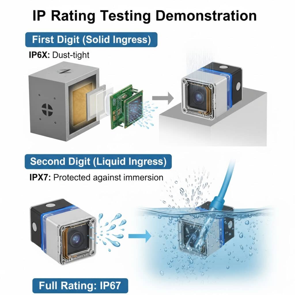
Clasificarea IP definește rezistența unui senzor la pătrunderea particulelor solide și a lichidelor utilizând un cod standardizat din două cifre. Prima cifră (0-6) indică protecția împotriva obiectelor solide, în timp ce a doua cifră (0-9) indică protecția împotriva lichidelor. Potrivirea corespunzătoare a clasificărilor IP la condițiile de mediu îmbunătățește în mod dramatic fiabilitatea și durata de viață a senzorului.
Înțelegerea elementelor de bază ale clasificării IP
Sistemul de clasificare IP (Ingress Protection) este definit de standardul IEC 60529 și constă în:
- Prefix IP: Indică standardul utilizat
- Prima cifră (0-6): Protecție împotriva obiectelor solide și a prafului
- A doua cifră (0-9): Protecție împotriva apei și a lichidelor
- Litere opționale: Protecții specifice suplimentare
Grafic de referință cuprinzător privind clasificarea IP
| Clasificare IP | Protecție solidă | Protecție împotriva lichidelor | Mediile adecvate | Aplicații tipice |
|---|---|---|---|---|
| IP00 | Nu există protecție | Nu există protecție | medii interioare curate și uscate | Echipament de laborator, componente interne |
| IP20 | Protejat împotriva obiectelor >12,5 mm | Nu există protecție | Mediile interioare de bază | Componente ale dulapului de comandă |
| IP40 | Protejat împotriva obiectelor >1mm | Nu există protecție | Utilizare generală în interior | Afișaje montate pe panou, comenzi închise |
| IP54 | Protejat împotriva prafului (intrare limitată) | Protejat împotriva stropilor de apă | Industrial ușor, protejat în exterior | Mașini generale, cutii de comandă exterioare |
| IP65 | Etanș la praf (fără pătrundere) | Protejat împotriva jeturilor de apă | Zone de spălare, expuse în aer liber | Echipamente de procesare a alimentelor, senzori de exterior |
| IP66 | Etanș la praf (fără pătrundere) | Protejat împotriva jeturilor puternice de apă | Spălare de înaltă presiune | Echipamente industriale grele, aplicații marine |
| IP67 | Etanș la praf (fără pătrundere) | Protejat împotriva imersiunii temporare (până la 1 m timp de 30 de minute) | Scufundare ocazională, spălare intensă | Pompe submersibile, medii de spălare |
| IP68 | Etanș la praf (fără pătrundere) | Protejat împotriva imersiunii continue (peste 1m, conform specificațiilor producătorului) | Scufundare continuă | Echipamente subacvatice, senzori submersibili |
| IP69K5 | Etanș la praf (fără pătrundere) | Protejat împotriva spălării la temperaturi înalte și presiune înaltă | Curățare cu aburi, spălare agresivă | Prelucrarea alimentelor, farmaceutică, lactate |
Prima cifră: Protecția împotriva particulelor solide
| Nivel | Protecție | Metoda de testare | Eficace împotriva |
|---|---|---|---|
| 0 | Nu există protecție | Niciuna | Nu există protecție |
| 1 | Obiecte >50mm | Sondă de 50 mm | Părți mari ale corpului (mână) |
| 2 | Obiecte >12.5mm | Sondă de 12,5 mm | Degete |
| 3 | Obiecte >2,5 mm | Sondă de 2,5 mm | Unelte, fire groase |
| 4 | Obiecte >1mm | Sondă de 1 mm | Majoritatea firelor, șuruburilor |
| 5 | Praf protejat | Test în camera de praf | Praf (este permisă intrarea limitată) |
| 6 | Strâns la praf | Test în camera de praf | Praf (fără pătrundere) |
A doua cifră: Protecție împotriva pătrunderii lichidelor
| Nivel | Protecție | Metoda de testare | Eficace împotriva |
|---|---|---|---|
| 0 | Nu există protecție | Niciuna | Nu există protecție |
| 1 | Picături de apă | Test de picurare a apei | Condens, picături ușoare |
| 2 | Picături de apă (înclinat la 15°) | Test de înclinare la 15° | Picături când este înclinat |
| 3 | Pulverizarea apei | Test de pulverizare | Ploaie, aspersoare |
| 4 | Stropirea apei | Test de stropire | Stropire din orice direcție |
| 5 | Jeturi de apă | Testul duzei de 6,3 mm | Spălare la presiune scăzută |
| 6 | Jeturi puternice de apă | Test duză de 12,5 mm | Mări puternice, spălări puternice |
| 7 | Imersiune temporară | 30min @ 1m imersiune | Inundații temporare |
| 8 | Imersiune continuă | Specificat de producător | Scufundare continuă |
| 9K | Jeturi de înaltă temperatură și înaltă presiune | 80°C, 8-10MPa, 10-15cm | Curățare cu aburi, spălare sub presiune |
Cerințe de clasificare IP specifice industriei
Diferitele industrii au provocări de mediu specifice care necesită o protecție adecvată:
Prelucrarea alimentelor și băuturilor
- Cerințe tipice: IP65 până la IP69K
- Provocările de mediu:
- Spălare frecventă cu substanțe chimice
- Curățare cu apă caldă de înaltă presiune
- Potențială contaminare cu particule alimentare
- Fluctuații de temperatură - Minim recomandat: IP66 pentru zone generale, IP69K pentru zone cu spălare directă
În aer liber și industriale grele
- Cerințe tipice: IP65 până la IP67
- Provocările de mediu:
- Expunerea la condițiile meteorologice
- Praf și particule în suspensie
- Expunere ocazională la apă
- Temperaturi extreme - Minim recomandat: IP65 pentru locații protejate, IP67 pentru poziții expuse
Producția de automobile
- Cerințe tipice: IP54 până la IP67
- Provocările de mediu:
- Expunerea la ulei și lichid de răcire
- Așchii de metal și praf
- Stropii de sudură
- Procese de curățare - Minim recomandat: IP65 pentru zone generale, IP67 pentru zone cu expunere la lichid de răcire
Prelucrarea chimică
- Cerințe tipice: IP65 până la IP68
- Provocările de mediu:
- Expunere la substanțe chimice corozive
- Cerințe de spălare
- Atmosfere potențial explozive
- Umiditate ridicată - Minim recomandat: IP66 cu rezistență chimică adecvată
Protecția senzorilor dincolo de clasificările IP
În timp ce ratingurile IP se referă la protecția împotriva pătrunderii, alți factori de mediu trebuie luați în considerare:
Rezistență chimică
- Verificarea compatibilității materialului carcasei cu substanțele chimice de proces
- Luați în considerare PTFE, PVDF sau oțel inoxidabil pentru medii chimice
- Evaluarea materialelor de garnitură și de etanșare
Considerații privind temperatura
- Verificarea intervalelor de temperatură de funcționare și de depozitare
- Luați în considerare efectele ciclurilor termice
- Evaluați nevoia de izolare sau răcire
Vibrații și protecție mecanică
- Verificați specificațiile privind vibrațiile și șocurile
- Luați în considerare opțiunile de montare pentru a amortiza vibrațiile
- Evaluați reducerea tensiunii și protecția cablurilor
Protecție electromagnetică
- Verificarea ratingurilor de imunitate EMC/EMI
- Luați în considerare cablurile ecranate și împământarea corespunzătoare
- Evaluați necesitatea unei protecții electrice suplimentare
Studiu de caz: Succes în selectarea clasificării IP
Am lucrat recent cu o fabrică de procesare a produselor lactate din California care se confrunta cu defecțiuni frecvente ale senzorilor din sistemul lor de curățare la fața locului (CIP). Senzorii existenți, cu clasificare IP65, cedau după 2-3 luni de funcționare.
Analiza a dezvăluit:
- Curățare zilnică cu soluție caustică la 85°C
- Ciclu săptămânal de curățare cu acid
- Pulverizare de înaltă presiune în timpul curățării manuale
- Cicluri de temperatură ambientală de la 5°C la 40°C
Prin implementarea senzorilor Bepto HygiSense cu:
- Clasificare IP69K pentru protecție la temperaturi ridicate, presiune ridicată
- carcasă din oțel inoxidabil 316L
- Garnituri EPDM pentru compatibilitate chimică
- Conexiuni de cabluri sigilate în fabrică
Rezultatele au fost semnificative:
- Zero defecțiuni ale senzorilor în peste 18 luni de funcționare
- Costuri de întreținere reduse de 85%
- Fiabilitatea sistemului îmbunătățită la 99,8%
- Timpul de funcționare a producției a crescut cu 3%
- Economii anuale de aproximativ $67,000
Ghid de selecție a clasificării IP în funcție de mediu
| Mediul înconjurător | Indicele IP minim recomandat | Considerații cheie |
|---|---|---|
| Interior, mediu controlat | IP40 | Protecție împotriva prafului, curățare ocazională |
| Interior industrial general | IP54 | Praf, expunere ocazională la apă |
| Atelier mecanic, producție ușoară | IP65 | Lichide de răcire, curățare, așchii metalice |
| În aer liber, protejat | IP65 | Ploaie, praf, schimbări de temperatură |
| În aer liber, expus | IP66/IP67 | Expunere directă la intemperii, submersie potențială |
| Mediile de spălare | IP66 până la IP69K | Produse chimice de curățare, presiune, temperatură |
| Aplicații submersibile | IP68 | Expunere continuă la apă, presiune |
| Prelucrarea alimentelor | IP69K | Igienizare, substanțe chimice, curățare la temperaturi ridicate |
Concluzie
Selectarea senzorilor pneumatici potriviți necesită înțelegerea procedurilor de calibrare a comutatorului de presiune, a metodelor de testare a timpului de răspuns al senzorului de debit și a gradului de protecție IP adecvat pentru mediul dvs. specific. Prin aplicarea acestor principii, puteți optimiza performanța sistemului, reduce costurile de întreținere și asigura funcționarea fiabilă a echipamentelor pneumatice în orice aplicație.
Întrebări frecvente cu privire la selectarea senzorului pneumatic
Cât de des trebuie calibrate presostatele într-un mediu industrial tipic?
În mediile industriale tipice, presostatele trebuie calibrate la fiecare 6-12 luni. Cu toate acestea, această frecvență trebuie mărită în cazul aplicațiilor critice, al mediilor dure sau în cazul în care s-au observat deviații la calibrările anterioare. Unele industrii reglementate pot avea cerințe specifice. Stabiliți un program de calibrare pe baza recomandărilor producătorului și a condițiilor dvs. specifice de funcționare, apoi ajustați pe baza datelor istorice de performanță.
Ce factori afectează timpul de răspuns al unui senzor de debit în afară de tehnologia senzorului în sine?
Dincolo de tehnologia senzorului, timpul de răspuns al senzorului de debit este afectat de factorii de instalare (diametrul conductei, poziția senzorului, distanța față de perturbațiile fluxului), caracteristicile mediului (vâscozitate, densitate, temperatură), procesarea semnalului (filtrare, rata de eșantionare, medie) și condițiile de mediu (fluctuații de temperatură, vibrații). În plus, magnitudinea modificării debitului măsurat influențează timpul de răspuns perceput - de obicei, modificările mai mari sunt detectate mai rapid decât variațiile subtile.
Pot utiliza un senzor cu un indice IP mai mic dacă adaug protecție suplimentară, cum ar fi o carcasă?
Da, puteți utiliza un senzor cu o clasificare IP mai scăzută în interiorul unei incinte corespunzătoare, cu condiția ca incinta în sine să îndeplinească cerințele de mediu și să fie instalată corespunzător. Cu toate acestea, această abordare introduce puncte potențiale de defecțiune la nivelul etanșărilor incintei și la intrarea cablurilor. Luați în considerare necesitățile de accesibilitate pentru întreținere, eventualele probleme de condens în interiorul incintei și cerințele de disipare a căldurii. Pentru aplicațiile critice, utilizarea de senzori cu un indice IP nativ adecvat este, în general, mai fiabilă.
Cum afectează histerezisul unui presostat performanța sistemului meu pneumatic?
Histerezisul unui presostat creează un tampon între punctele de activare și dezactivare, împiedicând ciclarea rapidă atunci când presiunea fluctuează în jurul punctului de referință. O histerezis prea mică poate provoca "chattering" (cicluri rapide de pornire/oprire), care deteriorează atât comutatorul, cât și echipamentul conectat, creând în același timp o performanță instabilă a sistemului. O histerezis prea mare poate duce la o variație excesivă a presiunii în sistem. Setările optime ale histerezisului echilibrează stabilitatea cu precizia controlului presiunii în funcție de cerințele specifice ale aplicației dvs.
Care este diferența dintre clasificările IP67 și IP68 și cum știu de care am nevoie?
Atât IP67, cât și IP68 oferă protecție completă împotriva pătrunderii prafului, dar diferă în ceea ce privește protecția împotriva apei: IP67 protejează împotriva imersiunii temporare (până la 30 de minute la 1 metru adâncime), în timp ce IP68 protejează împotriva imersiunii continue la adâncimi și durate specificate de producător. Alegeți IP67 pentru aplicațiile în care pot avea loc scufundări ocazionale, scurte. Alegeți IP68 atunci când echipamentul trebuie să funcționeze fiabil în timpul scufundării continue. Dacă adâncimea și durata imersiunii sunt specificate pentru aplicația dvs., potriviți aceste cerințe cu specificațiile IP68 ale producătorului.
Cum pot verifica dacă senzorul meu de debit răspunde suficient de rapid pentru aplicația mea?
Pentru a verifica dacă timpul de răspuns al senzorului de debit este adecvat, comparați timpul de răspuns T₉₀ specificat al senzorului (timpul pentru a atinge 90% din valoarea finală) cu fereastra de timp critică a aplicației dvs. Pentru o verificare precisă, efectuați teste de schimbare treptată utilizând un sistem de achiziție de date de mare viteză (eșantionare de cel puțin 10× mai rapidă decât timpul de răspuns preconizat) și o supapă cu acțiune rapidă. Creați modificări bruște ale debitului similare cu cele din aplicația dvs. în timp ce înregistrați ieșirea senzorului. Analizați curba de răspuns pentru a calcula parametrii de răspuns reali și comparați cu cerințele aplicației.
-
Oferă o definiție clară a histerezisului în contextul senzorilor și al sistemelor de control, explicându-l ca fiind fenomenul în care ieșirea la un anumit punct de intrare depinde de faptul dacă acel punct a fost abordat cu o intrare crescătoare sau descrescătoare. ↩
-
Descrie Industria 4.0, cunoscută și sub numele de a patra revoluție industrială, care se referă la automatizarea continuă a practicilor tradiționale de producție și industriale prin utilizarea tehnologiilor inteligente moderne, precum internetul obiectelor (IoT), cloud computing și inteligența artificială. ↩
-
Explică principiul de funcționare al debitmetrelor Coriolis, care utilizează efectul Coriolis pentru a măsura direct debitul masic prin vibrarea unui tub prin care trece fluidul și măsurarea torsiunii rezultate. ↩
-
detaliază standardul internațional IEC 60529, care clasifică gradele de protecție oferite de carcasele mecanice și carcasele electrice împotriva intruziunii, prafului, contactului accidental și apei. ↩
-
Oferă informații specifice cu privire la clasificarea IP69K, care este cel mai înalt nivel de protecție definit de standardele ISO 20653 și DIN 40050-9, însemnând protecție împotriva spălărilor la presiune ridicată și temperatură ridicată. ↩
