

Are you experiencing unexplained equipment failures, inconsistent pneumatic tool performance, or excessive air consumption? These common problems often trace back to improperly selected or maintained FRL (Filter, Regulator, Lubricator) units. The right FRL solution can immediately solve these costly issues.
Идеальный блок FRL должен соответствовать требованиям к расходу в вашей системе, обеспечивать надлежащую фильтрацию без чрезмерного перепада давления, обеспечивать точную смазку и легко интегрироваться с существующим оборудованием. Правильный выбор требует понимания соотношения фильтрации и перепада давления, принципов регулировки масляного тумана и модульной сборки.
I remember visiting a manufacturing plant in Ohio last year where they were replacing pneumatic tools every few months due to contamination issues. After analyzing their application and implementing properly sized FRL units with appropriate filtration, their tool life extended by 300% and air consumption decreased by 22%. Let me share what I’ve learned over my 15+ years in the pneumatic industry.
Оглавление
- Understanding Filtration Precision and Pressure Drop Relationships
- How to Properly Adjust Oil Mist Delivery in Lubricators
- Modular FRL Assembly and Installation Best Practices
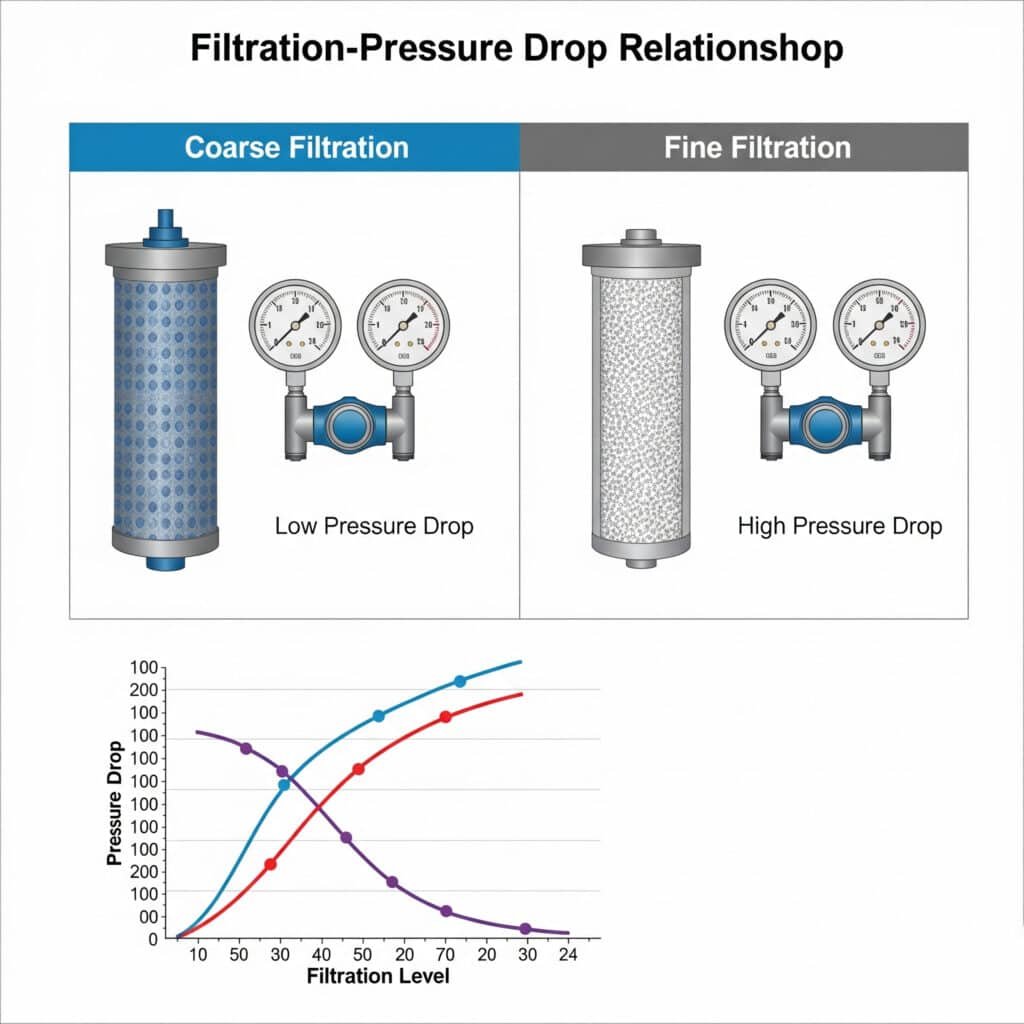
How Does Filtration Precision Affect Pressure Drop in Pneumatic Systems?
The relationship between filtration precision and pressure drop is critical for balancing air quality needs with system performance requirements.
Higher filtration precision (smaller micron ratings) creates greater resistance to airflow, resulting in increased pressure drop across the filter element. This pressure drop reduces available downstream pressure, potentially affecting tool performance and energy efficiency. Understanding this relationship helps select the optimal filtration level for your specific application.
Understanding the Filtration-Pressure Drop Model
The relationship between filtration precision and pressure drop follows a predictable pattern that can be modeled mathematically:
Basic Pressure Drop Equation
The pressure drop across a filter can be approximated by:
ΔP = k × Q² × (1/A) × (1/d⁴)
Где:
- ΔP = Pressure drop
- k = Filter coefficient (depends on filter design)
- Q = скорость потока
- A = Filter surface area
- d = Average pore diameter (related to micron rating)
This equation reveals several important relationships:
- Pressure drop increases with the square of flow rate
- Smaller pore sizes (higher filtration precision) dramatically increase pressure drop
- Larger filter surface area reduces pressure drop
Filtration Grades and Their Applications
Different applications require specific filtration levels:
| Filtration Grade | Micron Rating | Типовые применения | Expected Pressure Drop* |
|---|---|---|---|
| Coarse | 40-5 μm | General plant air, basic tools | 0.03-0.08 bar |
| Средний | 5-1 μm | Pneumatic cylinders, valves | 0.05-0.15 bar |
| Fine | 1-0.1 μm | Precision control systems | 0.10-0.25 bar |
| Ultra-fine | 0.1-0.01 μm | Instrumentation, food/pharma | 0.20-0.40 bar |
| Micro | <0.01 μm | Electronics, breathing air | 0.30-0.60 bar |
*At rated flow with clean element
Optimizing the Filtration-Pressure Drop Balance
To select the optimal filtration level:
Identify minimum required filtration level
– Consult equipment manufacturer specifications
– Consider industry standards (ISO 8573-11)
– Evaluate environmental conditionsCalculate system flow requirements
– Sum the consumption of all components
– Apply appropriate diversity factor
– Add safety margin (typically 30%)Size filter appropriately
– Select filter with flow capacity exceeding requirements
– Consider oversizing for reduced pressure drop
– Evaluate multiple-stage filtration optionsConsider filter element design
– Pleated elements offer larger surface area
– Coalescing filters2 remove both particles and liquids
– Activated carbon filters remove odors and vapors
Practical Example: Filtration-Pressure Drop Analysis
Last month, I consulted with a medical device manufacturer in Minnesota who was experiencing inconsistent performance in their assembly equipment. Their existing 5-micron filter was causing a 0.4 bar pressure drop at peak flow rates.
By analyzing their application:
- Required air quality: ISO 8573-1 Class 2.4.2
- System flow requirement: 850 NL/min
- Minimum operating pressure: 5.5 bar
We implemented a two-stage filtration solution:
- First stage: 5-micron general-purpose filter
- Second stage: 0.01-micron high-efficiency filter
- Both filters sized for 1500 NL/min capacity
Результаты были впечатляющими:
- Combined pressure drop reduced to 0.25 bar
- Air quality improved to ISO 8573-1 Class 1.4.1
- Equipment performance stabilized
- Energy consumption reduced by 8%
Pressure Drop Monitoring and Maintenance
To maintain optimal filtration performance:
Install pressure differential indicators
– Visual indicators show when elements need replacement
– Digital monitors provide real-time data
– Some systems offer remote monitoring capabilitiesEstablish regular maintenance schedules
– Replace elements before excessive pressure drop occurs
– Consider flow rate and contamination levels when setting intervals
– Document pressure drop trends over timeImplement automatic drain systems
– Prevent condensate accumulation
– Reduce maintenance requirements
– Ensure consistent performance
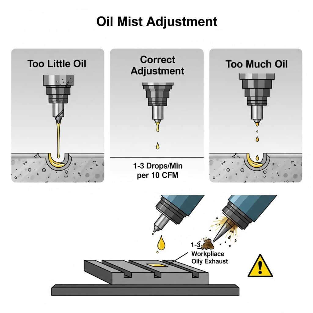
How Should You Adjust Oil Mist Delivery for Optimal Pneumatic Tool Lubrication?
Proper oil mist adjustment ensures pneumatic tools receive adequate lubrication without excessive oil consumption or environmental contamination.
Oil mist adjustment in lubricators should deliver between 1 and 3 drops of oil per minute for every 10 CFM (280 L/min) of air flow under operating conditions. Too little oil leads to premature tool wear, while excessive oil wastes lubricant, contaminates workpieces, and creates environmental issues.
Understanding Pneumatic Lubrication Fundamentals
Proper lubrication of pneumatic components is essential for:
- Reducing friction and wear
- Preventing corrosion
- Maintaining seals
- Optimizing performance
- Extending equipment life
Oil Mist Adjustment Standards and Guidelines
Industry standards provide guidance for proper lubrication:
ISO 8573-1 Oil Content Classifications
| ISO Class | Maximum Oil Content (mg/m³) | Типовые применения |
|---|---|---|
| Class 1 | 0.01 | Semiconductor, pharmaceutical |
| Класс 2 | 0.1 | Food processing, critical instrumentation |
| Class 3 | 1 | General pneumatics, standard automation |
| Class 4 | 5 | Heavy industrial tools, general manufacturing |
| Class X | >5 | Basic tools, non-critical applications |
Recommended Oil Delivery Rates
The general guideline for oil delivery is:
- 1-3 drops per minute per 10 CFM (280 L/min) of air flow
- Adjust based on specific tool manufacturer recommendations
- Increase slightly for high-speed or high-load applications
- Reduce for intermittent-use applications
Step-by-Step Oil Mist Adjustment Procedure
Follow this standardized procedure for precise oil mist adjustment:
Determine required oil delivery rate
– Check tool manufacturer specifications
– Calculate system air consumption
– Consider duty cycle and operating conditionsSelect appropriate lubricator oil
– ISO VG3 32 for general applications
– ISO VG 46 for higher temperature applications
– Food-grade oils for food processing
– Synthetic oils for extreme conditionsSet initial adjustment
– Fill lubricator bowl to recommended level
– Set adjustment knob to middle position
– Operate system at normal pressure and flowFine-tune the adjustment
– Observe drip rate through sight dome
– Count drops per minute during operation
– Adjust control knob accordingly
– Allow 5-10 minutes between adjustments for stabilizationVerify proper lubrication
– Check tool exhaust for light oil mist
– Inspect tool internals after break-in period
– Monitor oil consumption rate
– Adjust as needed based on tool performance
Common Oil Mist Adjustment Problems and Solutions
| Problem | Possible Causes | Решения |
|---|---|---|
| No oil delivery | Adjustment too low, clogged passages | Increase setting, clean lubricator |
| Excessive oil consumption | Adjustment too high, damaged sight dome | Reduce setting, replace damaged parts |
| Inconsistent oil delivery | Fluctuating air flow, low oil level | Stabilize air flow, maintain proper oil level |
| Oil not atomizing properly | Incorrect oil viscosity, low air flow | Use recommended oil, ensure minimum flow rate |
| Oil leakage | Damaged seals, overtightened bowl | Replace seals, hand-tighten only |
Case Study: Oil Mist Optimization
I recently worked with an automotive parts manufacturer in Michigan who was experiencing premature failure of their impact wrenches. Their existing lubrication system was delivering inconsistent oil mist, leading to tool damage.
After analyzing their application:
- Air consumption: 25 CFM per tool
- Duty cycle: 60%
- Operating pressure: 6.2 bar
We implemented these changes:
- Installed properly sized Bepto lubricators
- Selected ISO VG 32 pneumatic oil
- Set initial delivery rate to 3 drops per minute
- Implemented weekly verification procedure
Результаты оказались значительными:
- Tool life increased from 3 months to over 1 year
- Oil consumption reduced by 40%
- Maintenance costs decreased by $12,000 annually
- Productivity improved due to fewer tool failures
Oil Selection Guidelines for Different Applications
| Тип приложения | Recommended Oil Type | Viscosity Range | Delivery Rate |
|---|---|---|---|
| High-speed tools | Synthetic pneumatic oil | ISO VG 22-32 | 2-3 drops/min per 10 CFM |
| Impact tools | Pneumatic tool oil with Добавки EP4 | ISO VG 32-46 | 2-4 drops/min per 10 CFM |
| Precision mechanisms | Low-viscosity synthetic | ISO VG 15-22 | 1-2 drops/min per 10 CFM |
| Low temperature environments | Low pour point synthetic | ISO VG 22-32 | 2-3 drops/min per 10 CFM |
| Food processing | Food-grade (H1) lubricant | ISO VG 32 | 1-2 drops/min per 10 CFM |
What Are the Best Practices for Modular FRL Assembly and Installation?
Proper assembly and installation of modular FRL units ensures optimal performance, easy maintenance, and system longevity.
Modular FRL assembly requires careful planning of component sequence, proper orientation of flow direction, secure connection methods, and strategic placement within the pneumatic system. Following best practices for assembly and installation prevents leaks, ensures proper functionality, and facilitates future maintenance.
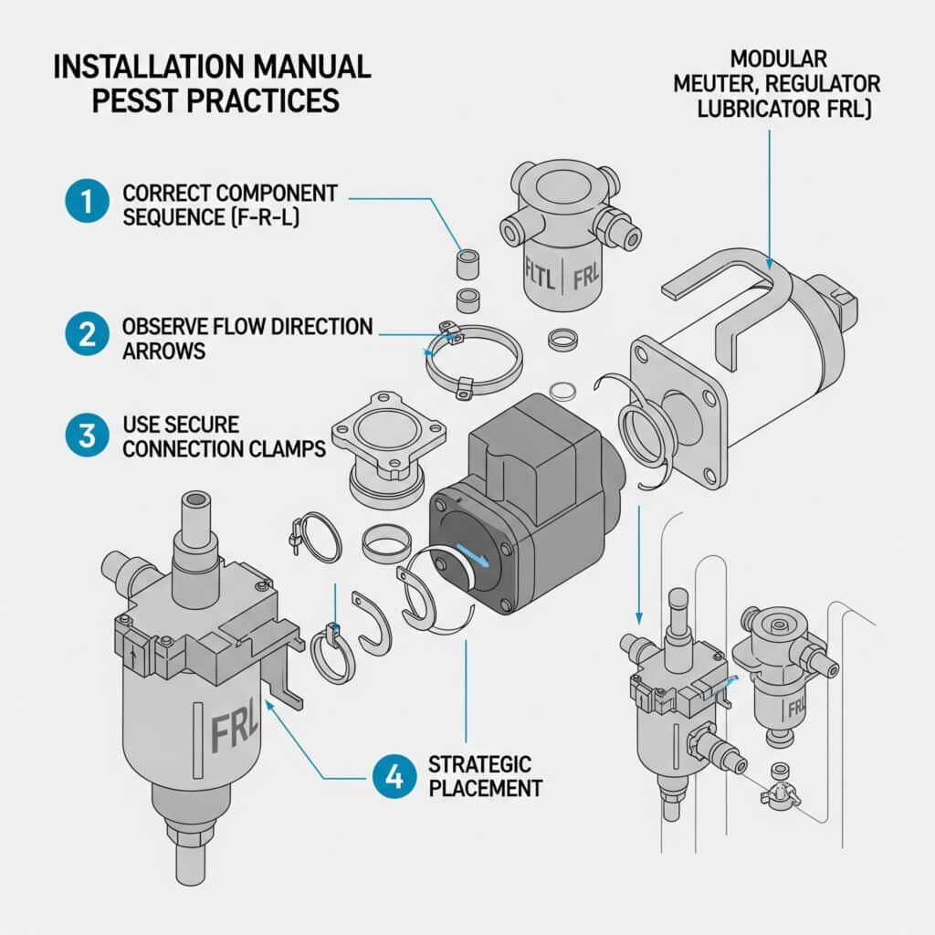
Understanding Modular FRL Components
Modern FRL units utilize modular designs that offer several advantages:
- Mix-and-match functionality
- Easy expansion
- Simplified maintenance
- Space-efficient installation
- Reduced potential leak points
Component Sequence and Configuration Guidelines
The proper sequence of FRL components is critical for optimal performance:
Standard Configuration (Flow Direction Left to Right)
Фильтр
– First component to remove contaminants
– Protects downstream components
– Available in various filtration gradesРегулятор
– Controls and stabilizes pressure
– Positioned after filter for protection
– May include pressure gauge or indicatorЛубрикатор
– Final component in the assembly
– Adds controlled oil mist to airflow
– Should be within 10 feet of end equipment
Additional Components
Beyond the basic F-R-L configuration, consider these additional modules:
- Soft-start valves
- Lockout/tagout valves
- Electronic pressure switches
- Flow control valves
- Pressure boosters
- Additional filtration stages
Modular Assembly Step-by-Step Guide
Follow these steps for proper assembly of modular FRL units:
Plan the configuration
– Determine required components
– Verify flow capacity compatibility
– Ensure port sizes match system requirements
– Consider future expansion needsPrepare components
– Check for shipping damage
– Remove protective caps
– Verify O-rings are properly seated
– Ensure moving parts operate freelyAssemble the modules
– Align connection features
– Insert joining clips or tighten connection bolts
– Follow manufacturer’s torque specifications
– Verify secure connection between modulesInstall accessories
– Mount pressure gauges
– Connect automatic drains
– Install pressure switches or sensors
– Add mounting brackets if neededTest the assembly
– Pressurize gradually
– Check for leaks
– Verify proper operation of each component
– Make necessary adjustments
Installation Best Practices
For optimal FRL performance, follow these installation guidelines:
Mounting Considerations
- Height: Install at convenient height (typically 4-5 feet from floor)
- Accessibility: Ensure easy access for adjustment and maintenance
- Orientation: Mount vertically with bowls down
- Clearance: Allow sufficient space below for bowl removal
- Support: Use proper wall brackets or panel mounting
Piping Recommendations
- Inlet piping: Size for minimal pressure drop (typically one size larger than FRL ports)
- Outlet piping: Match port size at minimum
- Bypass line: Consider installing bypass for maintenance
- Flexible connections: Use where vibration is present
- Slope: Slight downward slope in direction of flow helps drain condensate
Special Installation Considerations
- High-vibration environments: Use flexible connectors and secure mounting
- Наружные установки: Provide protection from direct weather exposure
- High-temperature areas: Ensure ambient temperature remains within specifications
- Multiple branch lines: Consider manifold systems with individual regulation
- Critical applications: Install redundant FRL paths
Modular FRL Troubleshooting Guide
| Problem | Possible Causes | Решения |
|---|---|---|
| Air leakage between modules | Damaged O-rings, loose connections | Replace O-rings, retighten connections |
| Pressure fluctuation | Undersized regulator, excessive flow | Increase regulator size, check for restrictions |
| Water in system despite filter | Saturated element, bypass flow | Replace element, verify proper sizing |
| Pressure drop across assembly | Clogged elements, undersized components | Clean or replace elements, increase component size |
| Difficulty maintaining settings | Vibration, damaged components | Add locking mechanisms, repair or replace components |
Case Study: Modular System Implementation
I recently helped a packaging equipment manufacturer in Pennsylvania redesign their pneumatic system. Their existing setup used individual components with threaded connections, resulting in frequent leaks and difficult maintenance.
By implementing a modular Bepto FRL system:
- Assembly time reduced from 45 minutes to 10 minutes per station
- Leak points decreased by 65%
- Maintenance time reduced by 75%
- System pressure stability improved significantly
- Future modifications became much simpler
The modular design allowed them to:
- Standardize components across multiple machines
- Reduce inventory of spare parts
- Quickly reconfigure systems as needed
- Add functionality without major rework
Modular Expansion Planning
When designing your FRL system, consider future needs:
Size for growth
– Select components with flow capacity for future expansion
– Consider expected increases in air consumptionLeave space for additional modules
– Plan physical layout for expansion
– Document current configurationStandardize on a modular platform
– Use consistent manufacturer and series
– Maintain inventory of common componentsDocument the system
– Create detailed assembly diagrams
– Record pressure settings and specifications
– Develop maintenance procedures
Заключение
Selecting the right FRL unit requires understanding the relationship between filtration precision and pressure drop, mastering oil mist adjustment for optimal lubrication, and following best practices for modular assembly and installation. By applying these principles, you can optimize your pneumatic system’s performance, reduce maintenance costs, and extend equipment life.
FAQs About FRL Unit Selection
What is the proper order for installing filter, regulator, and lubricator units?
The correct installation order is filter first, then regulator, and finally lubricator (F-R-L). This sequence ensures that contaminants are removed before air reaches the pressure regulator, and that regulated air pressure is stable before oil is added by the lubricator. Installing components in the wrong order can lead to regulator damage, inconsistent pressure, or improper lubrication.
How do I determine the right size FRL for my pneumatic system?
Determine the right FRL size by calculating your system’s maximum airflow requirement in CFM or L/min, then select an FRL with a flow capacity at least 25% higher than this requirement. Consider pressure drop across the FRL (should be less than 10% of line pressure), port sizes that match your piping, and filtration requirements based on your most sensitive components.
How often should filter elements be replaced in an FRL unit?
Filter elements should be replaced when the pressure differential indicator shows excessive pressure drop (typically 10 psi/0.7 bar), or according to a time-based maintenance schedule based on air quality and usage. In typical industrial environments, this ranges from monthly to annually. Systems with high contamination levels or critical applications may require more frequent replacement.
Can I use any type of oil in a pneumatic lubricator?
No, you should only use oils specifically designed for pneumatic systems. These oils have appropriate viscosity (typically ISO VG 32 or 46), contain rust and oxidation inhibitors, and are formulated to atomize properly. Never use hydraulic oils, motor oils, or general-purpose lubricants, as these can damage seals, create deposits, and may not atomize correctly in pneumatic systems.
What causes excessive pressure drop across an FRL assembly?
Excessive pressure drop across an FRL assembly is typically caused by undersized components relative to flow requirements, clogged filter elements, partially closed valves, restrictions in connectors or adapters, improper regulator adjustment, or internal damage to components. Regular maintenance, proper sizing, and monitoring pressure differential indicators can help prevent and identify these issues.
How do I know if my pneumatic tools are receiving proper lubrication?
Properly lubricated pneumatic tools will exhaust a fine mist of oil that may be visible against a dark background or felt as slight oiliness on a clean surface held near the exhaust. Tools should operate smoothly without excessive heating. Too little lubrication results in sluggish operation and premature wear, while excessive lubrication causes heavy oil discharge from the exhaust and potential contamination of workpieces.
-
Provides an overview of ISO 8573-1, the international standard that specifies the purity classes of compressed air with respect to particles, water, and oil, independent of the location in the system at which the air is measured. ↩
-
Describes the mechanism of coalescing filters, which are designed to remove fine water or oil aerosols from compressed air by forcing small liquid droplets to collect (coalesce) into larger ones that can then be drained away. ↩
-
Explains the ISO Viscosity Grade (VG) system, an international standard (ISO 3448) that classifies industrial lubricants according to their kinematic viscosity at 40°C. ↩
-
Details the function of Extreme Pressure (EP) additives, which are chemical compounds added to lubricants to prevent catastrophic wear and seizure of metal surfaces under high-load conditions by forming a protective surface film. ↩
