

Pnömatik sistem tasarımlarınızı mahkemede savunmaya hazır mısınız? Akışkan gücü endüstrisindeki teknik anlaşmazlıklar giderek daha karmaşık hale geldikçe, mühendisler ve teknik yöneticiler patent ihlali, ürün sorumluluğu ve standartlara uygunluğu düzenleyen yasal çerçeveleri anlamalıdır. Bu bilgi olmadan, iyi tasarlanmış sistemler bile maliyetli davaların merkezi haline gelebilir.
Bu teknik analiz pnömatik sistemlerdeki üç kritik hukuki ihtilaf alanını incelemektedir: patent ihlalinin belirlenmesi eşdeğerler doktrini1 ve kovuşturma geçmi̇şi̇ estoppeli̇2hata ağacı analizi ve FMEA metodolojileri yoluyla ürün sorumluluğu atfedilmesi ve belgelenmiş test, belgelendirme ve sürekli izleme yoluyla gerekli özeni gösteren standartlara uygunluk kanıt zincirleri. Üreticiler bu çerçeveleri anlayarak hem yersiz iddialara karşı savunma yapabilir hem de meşru anlaşmazlıklarda konumlarını güçlendirebilirler.
Olası anlaşmazlıkları daha etkili bir şekilde çözmenize yardımcı olmak için bu yasal çerçevelerin teknik yönlerini inceleyelim.
İçindekiler
- Pnömatik Teknolojisinde Patent İhlali Tespitleri Nasıl Yapılıyor?
- Pnömatik Sistem Sorumluluğu Davalarında Nedensellik Hangi Yöntemlerle Tespit Edilir?
- Etkili Bir Standartlara Uygunluk Kanıt Zinciri Nasıl Oluşturulur?
- Sonuç: Önleyici Hukuk Stratejilerinin Uygulanması
- Pnömatik Sistem Hukuki İhtilafları Hakkında SSS
Pnömatik Teknolojisinde Patent İhlali Tespitleri Nasıl Yapılıyor?
Pnömatik teknolojisindeki patent anlaşmazlıkları genellikle uzman olmayanların değerlendirmesinin zor olabileceği ince teknik ayrımlara dayanır. Mahkemelerin ihlali belirlemek için kullandığı teknik çerçeveleri anlamak, üreticilerin hem istemeden ihlalden kaçınmasına hem de kendi yeniliklerini savunmasına yardımcı olabilir.
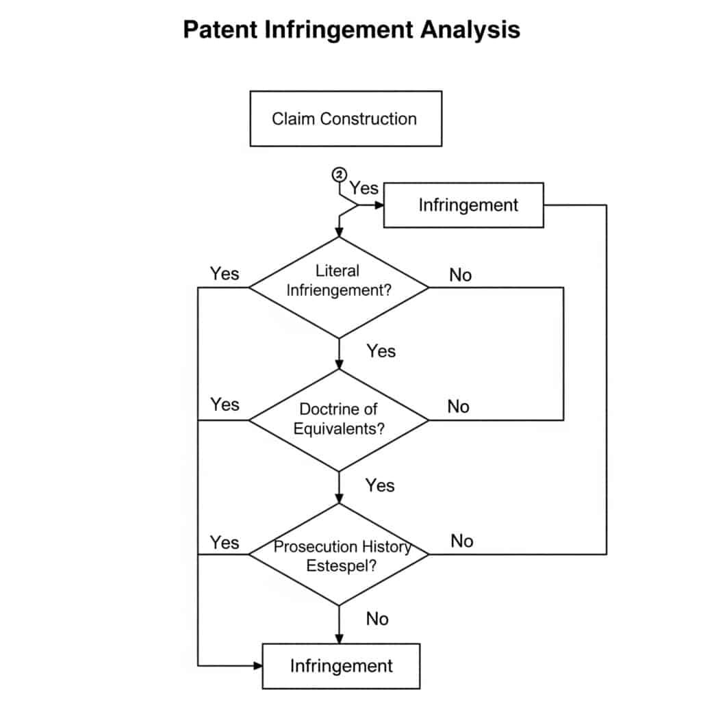
Pnömatik sistemlerde patent ihlali iki aşamalı bir analizle belirlenir: istem yapısı (patentin kapsamının yorumlanması) ve ardından suçlanan cihazla karşılaştırma. Gerçek ihlal, suçlanan cihazın en az bir istemdeki her unsuru içermesini gerektirirken, eşdeğerler doktrini korumayı büyük ölçüde aynı işlevi büyük ölçüde aynı şekilde ve büyük ölçüde aynı sonuçla yerine getiren cihazlara genişletir. Bununla birlikte, patent incelemesi sırasında istem kapsamının daraltılması durumunda, kovuşturma geçmişi estoppel'i bu doktrinin uygulanmasını sınırlayabilir.
Pnömatik Patentlerde Teknik Talep Yapısı
Talep inşası, herhangi bir ihlal analizinde patent taleplerinin kesin anlamını ve kapsamını belirleyen kritik ilk adımdır:
Pnömatik Patent Talep Yapısındaki Temel Unsurlar
| Element | Teknik Değerlendirme | Yasal Önem | Pnömatik Teknolojisinde Örnek |
|---|---|---|---|
| Talep Dili | Kesin teknik terminoloji | Gerçek kapsamı tanımlar | "Basınç dengelemeli akış kontrol vanası" özel teknik anlama sahiptir |
| Şartname | Detaylı teknik açıklamalar | Yorumlama için bağlam sağlar | Dahili vana bileşenlerini gösteren ayrıntılı kesit çizimleri |
| Kovuşturma Geçmişi | İnceleme sırasında yapılan teknik argümanlar | Talep kapsamını sınırlandırabilir | Özel mühür tasarımına dayalı olarak buluşu önceki teknikten ayıran argüman |
| Sıradan Anlam | Standart endüstri anlayışı | Belirli bir tanım olmadan varsayılan yorumlama | "Piston" akışkan gücü endüstrisinde iyi anlaşılmış bir anlama sahiptir |
| Araçlar-Artı-Fonksiyon | Yapısı olmayan işlevsel dil | Şartnamede açıklanan yapılarla sınırlıdır | "Basınçtan bağımsız olarak sabit akışı sürdürmek için araçlar" |
Pnömatik konumlandırma sistemlerini içeren yeni bir dava, teknik talep yapısının önemini göstermektedir. Patent, mahkemenin aktif basınç algılama ve dengeleme gerektirecek şekilde yorumladığı bir "basınç dengelemeli konumlandırma sistemi" talep ediyordu. Suçlanan sistem, aktif algılama olmadan benzer sonuçlar elde eden pasif bir basınç dengeleme mekanizması kullanıyordu. Talep yapısındaki bu teknik ayrım, ihlalin olmadığının tespit edilmesinde belirleyici olmuştur.
Pnömatik Teknolojisinde Eşdeğerler Analizi Doktrini
Gerçek ihlal bulunmadığında, eşdeğerler doktrini ihlali tespit etmek için alternatif bir yol sağlar:
Pnömatik Bileşenlere Uygulanan İşlev-Yol-Sonuç Testi
| Patent Unsuru | Fonksiyon | Yol | Sonuç | Eşdeğer Örnek |
|---|---|---|---|---|
| Pnömatik Conta | Sıvı sızıntısını önleyin | Yüzeyler arasında parazit oluşturma | Pressure containment | Different seal material with same interference fit |
| Valve Spool | Control flow direction | Blocking and opening flow paths | Directional control | Different spool geometry achieving same flow pattern |
| Cushioning Mechanism | Decelerate piston at end of stroke | Restricting exhaust flow | Reduced impact force | Alternative flow restriction method |
| Position Feedback | Determine piston location | Sensing piston position | Position data output | Different sensing technology with same accuracy |
| Control Algorithm | Maintain positioning accuracy | Processing feedback signals | Precise positioning | Alternative mathematical approach with same results |
The technical analysis under the doctrine of equivalents requires deep understanding of pneumatic system functionality. For example, in a case involving cushioning mechanisms, the patented design used an adjustable needle valve to restrict exhaust flow, while the accused product used a tapered spear with similar adjustment capability. Though structurally different, the court found equivalence because both performed the same function (flow restriction) in substantially the same way (creating variable orifice) to achieve the same result (controlled deceleration).
Prosecution History Estoppel in Pneumatic Patents
Prosecution history estoppel limits the doctrine of equivalents based on amendments and arguments made during patent prosecution:
Examples of Estoppel in Pneumatic Technology Patents
| Original Claim Element | Amendment/Argument During Prosecution | Resulting Limitation | Estoppel Effect |
|---|---|---|---|
| “Sealing means” | Amended to “elastomeric O-ring seal” | Limited to elastomeric materials | Cannot claim equivalence to metal seals |
| “Valve assembly” | Distinguished from prior art based on specific flow path | Limited to claimed flow path configuration | Cannot claim equivalence to alternative flow paths |
| “Position sensing system” | Argued novelty based on non-contact sensing | Limited to non-contact methods | Cannot claim equivalence to contact sensors |
| “Pressure range of 1-10 MPa” | Narrowed from “0.5-15 MPa” to overcome prior art | Limited to claimed range | Cannot claim equivalence outside specified range |
| “Cylinder with integrated cushioning” | Added “integrated” to overcome prior art | Limited to designs where cushioning is not separable | Cannot claim equivalence to add-on cushioning |
A significant case in the pneumatic industry involved a patent for a “non-contact position feedback system using magnetic coupling.” During prosecution, the applicant amended claims to specify “hall-effect sensors” to overcome prior art using optical sensors. When later asserting the patent against a competitor using magnetostrictive position sensing, the court found prosecution history estoppel prevented application of the doctrine of equivalents, despite the technical similarity in function.
Technical Analysis Framework for Infringement Assessment
When evaluating potential infringement, pneumatic manufacturers should follow this technical analysis framework:
Step-by-Step Technical Infringement Analysis
Claim Mapping
– Identify each element in the independent claims
– Create technical comparison chart mapping each element to accused device
– Identify any missing elements in literal analysis
– Document technical function of each elementTechnical Equivalence Analysis
– For each non-literal element, analyze:
– Function: Technical purpose of the element
– Way: Technical mechanism of operation
– Result: Technical outcome or effect
– Determine if differences are substantial from engineering perspectiveProsecution History Review
– Identify all technical amendments to relevant claims
– Analyze technical arguments made to overcome prior art
– Determine if current technical differences were surrendered
– Evaluate whether amendment was for patentability reasonsPrior Art Comparison
– Identify relevant prior art cited during prosecution
– Analyze technical differences between patent and prior art
– Determine if accused device is more similar to patent or prior art
– Evaluate whether accused device was expressly disclaimed
Case Study: Pneumatic Quick-Connect Coupling Patent Dispute
A recent dispute involved a patented quick-connect coupling with claims requiring “a locking mechanism comprising spring-loaded balls engaged with a circumferential groove.” The accused product used spring-loaded pins engaging with discrete recesses rather than a continuous groove.
Technical Analysis:
Claim Construction:
– “Balls” construed as spherical elements
– “Circumferential groove” construed as continuous channel around circumferenceLiteral Infringement:
– No literal infringement: pins ≠ balls, discrete recesses ≠ circumferential grooveDoctrine of Equivalents:
– Function: Both secure connection against axial separation
– Way: Both use spring-loaded elements engaging with mating features
– Result: Both create secure, releasable connectionProsecution History:
– Original claim: “locking elements engaging with mating features”
– Amended to: “spring-loaded balls engaged with a circumferential groove”
– Amendment made to overcome prior art with “various locking elements”Decision:
– Court found prosecution history estoppel applied
– Specific ball and groove configuration was surrendered during prosecution
– No infringement under doctrine of equivalents
This case demonstrates how technical distinctions in pneumatic designs, even when functionally similar, can be decisive in patent disputes when viewed through the lens of prosecution history.
Pnömatik Sistem Sorumluluğu Davalarında Nedensellik Hangi Yöntemlerle Tespit Edilir?
When pneumatic systems are involved in accidents or failures that cause injury or damage, establishing the technical cause is critical for determining liability. Courts rely on systematic engineering analysis methodologies to establish causation chains and apportion responsibility.
Product liability attribution in pneumatic system failures typically employs structured analytical methods including Fault Tree Analysis (FTA)3, Failure Mode and Effects Analysis (FMEA), and root cause analysis using the 5-Why method. These techniques establish causation by systematically evaluating potential failure modes, their effects, and probability of occurrence. Expert testimony then connects these technical findings to specific design decisions, manufacturing processes, maintenance procedures, or user actions to determine liability allocation.
Fault Tree Analysis in Pneumatic System Failure Cases
Fault Tree Analysis (FTA) is a top-down, deductive failure analysis that breaks down a system failure into its contributing factors:
FTA Structure for Common Pneumatic Failures
| Top Event | First-Level Causes | Second-Level Causes | Third-Level Causes | Probability Assessment |
|---|---|---|---|---|
| Catastrophic Cylinder Failure | Overpressurization | Control system failure | Software error | P = 1.2 × 10⁻⁵ |
| Sensor failure | P = 3.5 × 10⁻⁴ | |||
| Relief valve failure | Manufacturing defect | P = 2.1 × 10⁻⁵ | ||
| Kirlenme | P = 8.7 × 10⁻⁴ | |||
| Material failure | Manufacturing defect | Improper heat treatment | P = 3.2 × 10⁻⁵ | |
| Material impurity | P = 1.8 × 10⁻⁵ | |||
| Design inadequacy | Insufficient safety factor | P = 5.0 × 10⁻⁶ | ||
| Improper material selection | P = 2.4 × 10⁻⁵ | |||
| Improper usage | Exceeding specifications | Inadequate instructions | P = 1.3 × 10⁻³ | |
| Deliberate misuse | P = 3.6 × 10⁻⁴ |
In a recent case involving a pneumatic press that caused serious injury, FTA was crucial in establishing causation. The analysis revealed that while the immediate cause was overpressurization, the root cause was traced to a relief valve contaminated with manufacturing debris. The FTA demonstrated that the manufacturer’s inadequate cleaning procedures and quality control were the primary causes, rather than the system integrator’s design or the operator’s actions.
FMEA Methodology in Liability Attribution
Failure Mode and Effects Analysis (FMEA) evaluates potential failure modes and their impacts:
FMEA Example for Pneumatic Valve Assembly
| Bileşen | Potential Failure Mode | Potential Effects | Severity (1-10) | Potential Causes | Occurrence (1-10) | Current Controls | Detection (1-10) | RPN | Responsibility |
|---|---|---|---|---|---|---|---|---|---|
| Valve Seal | Sızıntı | System pressure loss, functional failure | 8 | Material degradation | 4 | Material specification | 5 | 160 | Designer |
| Improper installation | 3 | Assembly procedure | 4 | 96 | Assembler | ||||
| Chemical attack | 2 | Usage instructions | 7 | 112 | User | ||||
| Solenoid | Failure to energize | Valve stays in default position | 9 | Coil burnout | 2 | Electrical protection | 3 | 54 | Designer |
| Connection failure | 3 | Quality inspection | 4 | 108 | Manufacturer | ||||
| Power supply issue | 4 | System monitoring | 5 | 180 | System integrator | ||||
| Makara | Sticking/jamming | Valve fails to shift | 7 | Kirlenme | 5 | Filtration requirements | 6 | 210 | User/Maintainer |
| Excessive wear | 3 | Malzeme seçimi | 5 | 105 | Designer | ||||
| Manufacturing defect | 2 | Quality control | 4 | 56 | Manufacturer |
FMEA has proven particularly valuable in cases where multiple parties share potential responsibility. In a case involving a pneumatic system failure in an automated production line, the FMEA revealed that while contamination was the immediate cause of a valve failure, the system lacked adequate filtration (designer responsibility) and maintenance procedures failed to include filter inspection (user responsibility). The court used this analysis to apportion liability 70% to the designer and 30% to the user.
Root Cause Analysis Using 5-Why Method
The 5-Why method traces a failure to its fundamental cause through successive questioning:
5-Why Analysis Example: Pneumatic Cylinder Rod Failure
| Level | Question | Answer | Responsible Party |
|---|---|---|---|
| 1 | Why did the system fail? | The cylinder rod broke during operation | Unknown |
| 2 | Why did the rod break? | Material fatigue at the thread root | Unknown |
| 3 | Why did fatigue occur at this location? | Stress concentration due to improper thread design | Designer |
| 4 | Why was the thread improperly designed? | Thread relief was omitted from the design | Designer |
| 5 | Why was the thread relief omitted? | Design standard was not followed | Designer |
| 6 (Additional) | Why wasn’t the design standard followed? | Designer was not trained on company standards | Management |
This method is particularly effective in court because it creates a clear narrative chain that judges and juries can follow. In a case involving a pneumatic cylinder failure that caused property damage, the 5-Why analysis traced the failure to a specific design decision that omitted a critical stress relief feature, clearly establishing designer liability.
Technical Factors in Comparative Negligence Assessment
Many jurisdictions apply comparative negligence principles, requiring technical analysis to apportion responsibility:
Comparative Negligence Factors in Pneumatic System Failures
| Party | Technical Responsibilities | Common Failure Points | Evidence Sources | Typical Liability Range |
|---|---|---|---|---|
| Designer | Safe design within standards | Inadequate safety factors, missing safeguards | Design documentation, risk assessments, calculations | 30-100% |
| Manufacturer | Proper production to specifications | Manufacturing defects, quality control failures | Production records, QC documentation, material certifications | 20-100% |
| Installer | Correct system integration | Improper connections, inadequate testing | Installation procedures, test records, commissioning reports | 10-80% |
| Maintainer | Appropriate maintenance | Neglected maintenance, improper repairs | Maintenance records, repair documentation, inspection reports | 10-70% |
| User | Operation within specifications | Misuse, bypassing safety features | Training records, operating procedures, witness testimony | 0-100% |
A significant case involved a pneumatic lifting system that failed, causing injury. Technical analysis determined that the manufacturer used incorrect heat treatment (30% responsibility), the installer failed to perform pressure testing (20% responsibility), and the user had bypassed a safety valve (50% responsibility). The court apportioned damages according to this technical assessment of comparative negligence.
Expert Witness Technical Analysis Framework
Expert witnesses in pneumatic liability cases typically follow this framework:
Expert Analysis Methodology
System Examination
– Physical examination of failed components
– Non-destructive testing where applicable
– Dimensional analysis and comparison to specifications
– Documentation of physical evidenceDocumentation Review
– Design specifications and calculations
– Manufacturing records and quality control data
– Maintenance and inspection history
– Operating procedures and user manuals
– Applicable standards and regulationsFailure Analysis
– Metallurgical or materials analysis
– Stress analysis and simulation
– Performance testing of exemplar components
– Reconstruction of failure sequenceCausation Determination
– Application of FTA, FMEA, and 5-Why methods
– Evaluation of alternative scenarios
– Probability assessment of contributing factors
– Determination of most likely failure sequenceResponsibility Assessment
– Mapping of technical failures to responsible parties
– Evaluation of standard of care
– Assessment of foreseeability
– Quantification of contribution to failure
Case Study: Pneumatic Clamp System Failure
A pneumatic clamping system in a manufacturing facility failed, causing a workpiece to be ejected and injuring an operator. The technical investigation revealed:
FTA Analysis:
- Top Event: Clamp pressure loss during operation
- Primary Cause: Check valve failure allowing back-flow
- Secondary Causes: Improper valve material for hydraulic fluid, system pressure exceeding valve rating
FMEA Findings:
- Component: Check valve
- Failure Mode: Internal seal degradation
- Effect: Pressure loss during operation
- Cause: Chemical incompatibility with fluid
- Responsibility: Designer specified incorrect material
5-Why Analysis:
- Why was the operator injured? Workpiece ejected from clamp
- Why was the workpiece ejected? Clamp lost pressure during operation
- Why did clamp lose pressure? Check valve failed to maintain pressure
- Why did check valve fail? Internal seal degraded
- Why did seal degrade? Incompatible with hydraulic fluid used
Technical Conclusion:
The system designer specified a standard nitrile-sealed check valve, but the system used phosphate ester hydraulic fluid which is incompatible with nitrile. The designer’s specification was technically incorrect for the application, making them primarily liable. However, the system integrator failed to identify this incompatibility during design review, contributing 30% comparative negligence.
This case demonstrates how technical analysis methodologies provide a structured framework for determining causation and apportioning liability in pneumatic system failures.
Etkili Bir Standartlara Uygunluk Kanıt Zinciri Nasıl Oluşturulur?
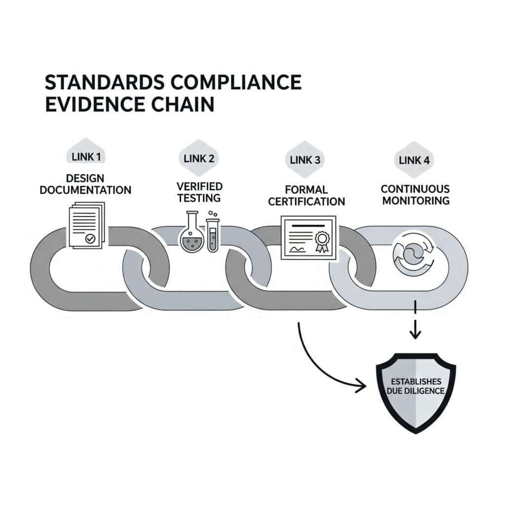
Standards compliance is often the central issue in pneumatic system legal disputes. Manufacturers must not only comply with applicable standards but also maintain a comprehensive evidence chain demonstrating that compliance throughout the product lifecycle.
An effective standards compliance evidence chain for pneumatic systems consists of four key elements: comprehensive documentation of design validation against specific standard requirements, verified testing protocols with calibrated equipment and witnessed procedures, formal certification through accredited third-party assessment, and continuous monitoring systems that track ongoing compliance through the product lifecycle. This chain establishes due diligence and can be decisive in defending against liability claims.
Mapping Pneumatic System Requirements to Standards
The foundation of compliance is a clear mapping of system requirements to specific standards:
Standards Mapping for Pneumatic Systems
| System Aspect | Applicable Standards | Key Requirements | Documentation Required |
|---|---|---|---|
| Pressure Equipment Safety | ISO 4414, ASME B&PV Code | Maximum allowable working pressure, safety factors, pressure testing | Design calculations, material certifications, test reports |
| Control System Safety | ISO 138494, IEC 62061 | Performance Level (PL) or Safety Integrity Level (SIL), fault tolerance | Risk assessment, circuit validation, component certificates |
| Electrical Components | IEC 60204, NFPA 79 | Insulation, grounding, protection against electric shock | Electrical schematics, insulation testing, ground continuity tests |
| Tehlikeli Ortamlar | ATEX Directive, NEC 500 | Explosion protection methods, temperature classifications | Zone classification, component certifications, installation verification |
| Çevresel Koşullar | IEC 60529, MIL-STD-810 | Ingress protection, temperature range, vibration resistance | Environmental testing reports, IP certification, climate testing |
A recent legal case involved a pneumatic system that failed in a food processing environment. The manufacturer claimed compliance with ISO 4414 but could not produce documentation showing how specific clause requirements were met in the design. The court ruled that merely claiming compliance without a detailed requirements traceability matrix was insufficient to establish due diligence.
Design Validation Documentation
Design validation forms the first link in the compliance evidence chain:
Design Validation Documentation Requirements
| Validation Element | Documentation Type | Technical Content | Yasal Önem |
|---|---|---|---|
| Requirements Traceability | Requirements Matrix | Mapping of each standard clause to design features | Demonstrates comprehensive standards consideration |
| Design Calculations | Engineering Analysis | Safety factors, pressure ratings, cycle life calculations | Proves technical due diligence in design |
| Risk Değerlendirmesi | ISO 12100 Analysis | Hazard identification, risk estimation, risk reduction measures | Shows foreseeable risks were addressed |
| Design Reviews | Review Reports | Independent verification of design compliance | Establishes peer validation of compliance claims |
| Malzeme Seçimi | Material Specifications | Compatibility, strength, environmental resistance | Demonstrates appropriate material selection process |
| Simulation Results | FEA/CFD Reports | Stress analysis, flow modeling, thermal analysis | Shows advanced validation of critical parameters |
In a dispute involving a pneumatic system that failed due to material incompatibility, the manufacturer who maintained comprehensive material selection documentation—including compatibility testing and environmental exposure analysis—successfully defended against liability claims by demonstrating thorough due diligence in the design process.
Testing Protocol Verification
Testing protocols provide empirical evidence of compliance:
Testing Evidence Requirements
| Test Type | Protocol Requirements | Documentation Elements | Verification Methods |
|---|---|---|---|
| Prototype Testing | Written test plans referencing standards | Test setup, procedures, acceptance criteria | Independent witness, video documentation |
| Production Testing | Documented test procedures | Pass/fail criteria, test equipment specifications | Statistical process control, calibration records |
| Type Testing | Testing to specific standard requirements | Complete test reports with raw data | Accredited laboratory certification |
| Destructive Testing | Defined failure criteria | Photographic evidence, measurement data | Material analysis reports |
| Field Testing | In-situ test protocols | Environmental conditions, operational parameters | Third-party verification |
| Accelerated Life Testing | Correlation to real-world conditions | Time compression calculations, failure analysis | Statistical validity documentation |
The importance of proper test documentation was highlighted in a case where a manufacturer claimed their pneumatic components were rated for hazardous environments. When a system failure led to an industrial accident, the investigation revealed that while testing had been performed, the test equipment calibration was expired and the test procedures deviated from standard requirements. The court ruled that invalid testing procedures broke the compliance evidence chain.
Certification Documentation
Formal certification provides third-party validation of compliance:
Certification Evidence Requirements
| Certification Type | Issuing Authority | Documentation Required | Maintenance Requirements |
|---|---|---|---|
| Component Certification | Notified Bodies, UL, CSA | Certificates with specific standards reference | Renewal documentation, change management |
| Quality System Certification | ISO 9001 Registrars | Audit reports, non-conformance resolutions | Surveillance audit records, management reviews |
| Product Type Approval | Industry Certification Bodies | Type examination certificates, technical files | Periodic re-certification, modification approvals |
| Personnel Certification | Professional Organizations | Training records, competency assessments | Continuing education documentation |
| Process Certification | Specialized Certification Bodies | Process validation records, capability studies | Process monitoring data, re-validation records |
| Self-Declaration | Manufacturer | Declaration of Conformity with standards list | Technical file maintenance, change control records |
A manufacturer of pneumatic components for medical devices successfully defended against liability claims following a patient injury by producing a comprehensive technical file supporting their CE marking5. The file included detailed certification documentation showing how each essential requirement was met, validated, and maintained through product modifications.
Continuous Monitoring Systems
Ongoing compliance monitoring completes the evidence chain:
Continuous Monitoring Evidence Requirements
| Monitoring Aspect | İzleme Yöntemleri | Documentation Required | Legal Relevance |
|---|---|---|---|
| Product Performance | Field performance tracking | Statistical analysis, trend reports | Demonstrates ongoing compliance verification |
| Customer Feedback | Complaint handling system | Complaint logs, resolution documentation | Shows responsiveness to potential issues |
| Manufacturing Process | Statistical Process Control | Control charts, capability studies | Proves consistent production within specifications |
| Design Changes | Change management system | Impact analysis, re-validation records | Demonstrates compliance maintenance through changes |
| Field Incidents | Incident investigation process | Root cause analysis, corrective actions | Shows due diligence in addressing field issues |
| Regulatory Updates | Standards monitoring process | Gap analysis, implementation plans | Demonstrates awareness of evolving requirements |
In a significant case, a manufacturer of pneumatic control systems for industrial equipment faced liability claims after a system failure. Despite the failure, they successfully limited liability by demonstrating a robust monitoring system that had identified similar potential issues in other installations, implemented corrective actions, and attempted to notify all customers—including the plaintiff who had not responded to recall notices. This evidence of proactive monitoring significantly reduced their liability exposure.
Building a Defensible Technical File
A comprehensive technical file integrates all elements of the compliance evidence chain:
Technical File Structure for Legal Defense
Product Identification and Description
– Detailed technical specifications
– Intended use and limitations
– System boundaries and interfaces
– Component identification and sourcingStandards Compliance Documentation
– Standards applicability assessment
– Clause-by-clause compliance documentation
– Gap analysis and justifications
– Alternative methods where applicableDesign Documentation
– Design calculations and analyses
– Material specifications and justifications
– Risk assessments and mitigations
– Design review recordsVerification and Validation
– Test plans and procedures
– Test reports with raw data
– Simulation reports
– Validation protocols and resultsManufacturing Controls
– Production process specifications
– Quality control procedures
– Inspection methods and criteria
– Non-conformance handlingPost-Market Surveillance
– Field monitoring procedures
– Complaint handling processes
– Incident investigation methods
– Corrective action proceduresChange Management
– Change control procedures
– Impact assessment methods
– Re-validation requirements
– Customer notification processes
Case Study: Pneumatic System Compliance Dispute
A pneumatic control system for an industrial press was involved in a workplace accident resulting in operator injury. The manufacturer faced liability claims based on alleged non-compliance with safety standards.
The Evidence Chain Analysis:
Design Validation:
– Manufacturer maintained comprehensive risk assessment per ISO 12100
– Performance Level determination according to ISO 13849-1 showed PL=d requirement
– Circuit validation documentation demonstrated dual-channel architecture with diagnostics
– Missing: Specific calculation for pneumatic component fault exclusionTesting Evidence:
– Type testing of control system by accredited laboratory
– Fault injection testing documented for electrical components
– Missing: Documented testing of pneumatic component failure modesCertification:
– CE marking with Declaration of Conformity
– ISO 9001 certification for quality management system
– Missing: Specific certification for safety-related pneumatic componentsContinuous Monitoring:
– Field performance tracking system in place
– Previous similar incidents investigated with corrective actions
– Design changes implemented based on field data
– Missing: Evidence that this specific risk was identified and addressed
Court Finding:
The court determined that while the manufacturer had a generally robust compliance system, the specific gap in pneumatic component validation created a broken link in the evidence chain. The manufacturer was found partially liable because they could not demonstrate complete due diligence specific to the failure mode that caused the accident.
This case demonstrates that a compliance evidence chain is only as strong as its weakest link, and that comprehensive documentation across all system aspects is essential for an effective legal defense.
Sonuç: Önleyici Hukuk Stratejilerinin Uygulanması
Understanding the technical aspects of legal frameworks for patent infringement, product liability, and standards compliance enables pneumatic system manufacturers to implement effective preventive strategies. By proactively addressing these areas, companies can both reduce litigation risk and strengthen their position when disputes arise.
Key Preventive Strategies
Patent Risk Management
– Implement systematic freedom-to-operate analyses
– Document design-around decisions with technical rationales
– Maintain comprehensive development records showing independent creation
– Establish clear procedures for handling third-party patent noticesProduct Liability Prevention
– Integrate FMEA and FTA methodologies into design processes
– Implement robust design review procedures with documented risk assessments
– Develop comprehensive user instructions with clear warnings
– Establish incident investigation procedures that preserve evidenceStandards Compliance Management
– Create and maintain standards traceability matrices
– Implement formal design validation processes against standards requirements
– Establish comprehensive testing protocols with proper documentation
– Develop continuous monitoring systems for ongoing compliance
By applying these technical frameworks to legal risk management, pneumatic system manufacturers can significantly reduce their exposure to costly disputes while building stronger defensive positions when litigation does occur.
Pnömatik Sistem Hukuki İhtilafları Hakkında SSS
Patent ihlali iddialarına karşı savunma yapmak için hangi belgeler tutulmalıdır?
Aşağıdakileri içeren kapsamlı tasarım geliştirme kayıtları tutun: tarihli tasarım konseptleri ve yinelemeleri, dikkate alınan alternatif tasarımlar, tasarım kararları için teknik gerekçeler, geliştirme sırasında incelenen önceki teknikler, bağımsız geliştirme kanıtları ve faaliyete geçme özgürlüğü analizleri. Bu kayıtlar geliştirme ile eşzamanlı olarak oluşturulmalı, uygun şekilde tarihlendirilmeli ve güvenli, kurcalanmaya karşı korumalı bir sistemde muhafaza edilmelidir. Buna ek olarak, kalifiye danışmanlardan alınan her türlü patent izni görüşünün kayıtlarını ve potansiyel olarak sorunlu patentler tespit edilmişse her türlü tasarım aşma çabasının belgelerini muhafaza edin.
Üreticiler gelişen standartlara uyumu nasıl etkili bir şekilde belgeleyebilir?
İlgili standart güncellemelerini takip eden ve değişiklikler meydana geldiğinde boşluk analizleri gerçekleştiren bir standart izleme sistemi uygulayın. Belirli ürün özelliklerini standart gerekliliklerle eşleştiren ve her bir gerekliliğin nasıl karşılandığını açık bir şekilde belgeleyen bir standart uyumluluk matrisi bulundurun. Her standart revizyonu için resmi bir etki değerlendirmesi yapın ve belgeleyin, gerekli tasarım veya süreç değişikliklerini uygulayın, uygun doğrulamayı gerçekleştirin ve teknik dosyayı buna göre güncelleyin. Üretim sırasında geçerli olan standartlara uygunluğu göstermek için bu belgelerin tüm sürümlerini saklayın.
Karmaşık pnömatik sistem arızalarında sorumluluğu paylaştırmanın en etkili yolu nedir?
En etkili yaklaşım birden fazla teknik analiz metodolojisini bir araya getirmektedir. Katkıda bulunan tüm potansiyel faktörleri belirlemek için kapsamlı bir Hata Ağacı Analizi (FTA) ile başlayın. Her bir faktörün göreceli etkisini değerlendirmek için Hata Modu ve Etkileri Analizi (FMEA) ile devam edin. Her bir önemli faktörü kök nedenine kadar izlemek için 5-Neden yöntemini uygulayın. Ardından bu teknik bulguları tasarım kararları, üretim süreçleri, kurulum prosedürleri, bakım faaliyetleri ve kullanıcı operasyonlarına dayalı belirli sorumluluklarla eşleştirin. Bu çok yöntemli yaklaşım, yasal incelemeye dayanabilecek sorumluluk paylaşımı için savunulabilir bir teknik temel sağlar.
-
Provides a legal explanation of the doctrine of equivalents, a U.S. patent law principle that allows courts to find a party liable for patent infringement even if the infringing device does not fall within the literal scope of a patent claim. ↩
-
Details the legal principle of prosecution history estoppel (or file wrapper estoppel), which prevents a patent owner from using the doctrine of equivalents for claim elements that were narrowed during patent prosecution to overcome prior art. ↩
-
Offers a comprehensive overview of Fault Tree Analysis (FTA), a top-down, deductive failure analysis in which a system’s failure is traced back to its root causes through a series of logical steps. ↩
-
Explains the ISO 13849 standard, which provides safety requirements and guidance on the principles for the design and integration of safety-related parts of control systems, including the determination of Performance Levels (PL). ↩
-
Describes the CE marking, a mandatory conformity marking for certain products sold within the European Economic Area (EEA), which certifies that the product meets EU health, safety, and environmental protection requirements. ↩
