Pnömatik sistem tasarımlarınızı mahkemede savunmaya hazır mısınız? Akışkan gücü endüstrisindeki teknik anlaşmazlıklar giderek daha karmaşık hale geldikçe, mühendisler ve teknik yöneticiler patent ihlali, ürün sorumluluğu ve standartlara uygunluğu düzenleyen yasal çerçeveleri anlamalıdır. Bu bilgi olmadan, iyi tasarlanmış sistemler bile maliyetli davaların merkezi haline gelebilir.
Bu teknik analiz pnömatik sistemlerdeki üç kritik hukuki ihtilaf alanını incelemektedir: patent ihlalinin belirlenmesi eşdeğerler doktrini1 ve kovuşturma geçmi̇şi̇ estoppeli̇2hata ağacı analizi ve FMEA metodolojileri yoluyla ürün sorumluluğu atfedilmesi ve belgelenmiş test, belgelendirme ve sürekli izleme yoluyla gerekli özeni gösteren standartlara uygunluk kanıt zincirleri. Üreticiler bu çerçeveleri anlayarak hem yersiz iddialara karşı savunma yapabilir hem de meşru anlaşmazlıklarda konumlarını güçlendirebilirler.
Olası anlaşmazlıkları daha etkili bir şekilde çözmenize yardımcı olmak için bu yasal çerçevelerin teknik yönlerini inceleyelim.
İçindekiler
- Pnömatik Teknolojisinde Patent İhlali Tespitleri Nasıl Yapılıyor?
- Pnömatik Sistem Sorumluluğu Davalarında Nedensellik Hangi Yöntemlerle Tespit Edilir?
- Etkili Bir Standartlara Uygunluk Kanıt Zinciri Nasıl Oluşturulur?
- Sonuç: Önleyici Hukuk Stratejilerinin Uygulanması
- Pnömatik Sistem Hukuki İhtilafları Hakkında SSS
Pnömatik Teknolojisinde Patent İhlali Tespitleri Nasıl Yapılıyor?
Pnömatik teknolojisindeki patent anlaşmazlıkları genellikle uzman olmayanların değerlendirmesinin zor olabileceği ince teknik ayrımlara dayanır. Mahkemelerin ihlali belirlemek için kullandığı teknik çerçeveleri anlamak, üreticilerin hem istemeden ihlalden kaçınmasına hem de kendi yeniliklerini savunmasına yardımcı olabilir.
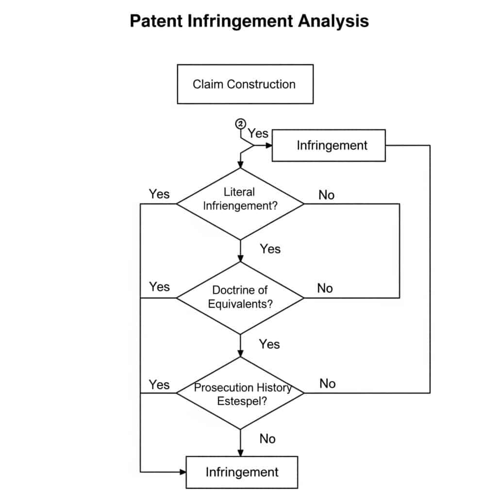
Pnömatik sistemlerde patent ihlali iki aşamalı bir analizle belirlenir: istem yapısı (patentin kapsamının yorumlanması) ve ardından suçlanan cihazla karşılaştırma. Gerçek ihlal, suçlanan cihazın en az bir istemdeki her unsuru içermesini gerektirirken, eşdeğerler doktrini korumayı büyük ölçüde aynı işlevi büyük ölçüde aynı şekilde ve büyük ölçüde aynı sonuçla yerine getiren cihazlara genişletir. Bununla birlikte, patent incelemesi sırasında istem kapsamının daraltılması durumunda, kovuşturma geçmişi estoppel'i bu doktrinin uygulanmasını sınırlayabilir.
Pnömatik Patentlerde Teknik Talep Yapısı
Talep inşası, herhangi bir ihlal analizinde patent taleplerinin kesin anlamını ve kapsamını belirleyen kritik ilk adımdır:
Pnömatik Patent Talep Yapısındaki Temel Unsurlar
| Element | Teknik Değerlendirme | Yasal Önem | Pnömatik Teknolojisinde Örnek |
|---|---|---|---|
| Talep Dili | Kesin teknik terminoloji | Gerçek kapsamı tanımlar | "Basınç dengelemeli akış kontrol vanası" özel teknik anlama sahiptir |
| Şartname | Detaylı teknik açıklamalar | Yorumlama için bağlam sağlar | Dahili vana bileşenlerini gösteren ayrıntılı kesit çizimleri |
| Kovuşturma Geçmişi | İnceleme sırasında yapılan teknik argümanlar | Talep kapsamını sınırlandırabilir | Özel mühür tasarımına dayalı olarak buluşu önceki teknikten ayıran argüman |
| Sıradan Anlam | Standart endüstri anlayışı | Belirli bir tanım olmadan varsayılan yorumlama | "Piston" akışkan gücü endüstrisinde iyi anlaşılmış bir anlama sahiptir |
| Araçlar-Artı-Fonksiyon | Yapısı olmayan işlevsel dil | Şartnamede açıklanan yapılarla sınırlıdır | "Basınçtan bağımsız olarak sabit akışı sürdürmek için araçlar" |
Pnömatik konumlandırma sistemlerini içeren yeni bir dava, teknik talep yapısının önemini göstermektedir. Patent, mahkemenin aktif basınç algılama ve dengeleme gerektirecek şekilde yorumladığı bir "basınç dengelemeli konumlandırma sistemi" talep ediyordu. Suçlanan sistem, aktif algılama olmadan benzer sonuçlar elde eden pasif bir basınç dengeleme mekanizması kullanıyordu. Talep yapısındaki bu teknik ayrım, ihlalin olmadığının tespit edilmesinde belirleyici olmuştur.
Pnömatik Teknolojisinde Eşdeğerler Analizi Doktrini
Gerçek ihlal bulunmadığında, eşdeğerler doktrini ihlali tespit etmek için alternatif bir yol sağlar:
Pnömatik Bileşenlere Uygulanan İşlev-Yol-Sonuç Testi
| Patent Unsuru | Fonksiyon | Yol | Sonuç | Eşdeğer Örnek |
|---|---|---|---|---|
| Pnömatik Conta | Sıvı sızıntısını önleyin | Yüzeyler arasında parazit oluşturma | Basınç muhafazası | Aynı girişim uyumuna sahip farklı conta malzemesi |
| Valf Makarası | Kontrol akış yönü | Akış yollarını bloke etme ve açma | Yön kontrolü | Aynı akış modeline ulaşan farklı makara geometrisi |
| Yastıklama Mekanizması | Strok sonunda pistonu yavaşlatın | Egzoz akışını kısıtlama | Azaltılmış darbe kuvveti | Alternatif akış kısıtlama yöntemi |
| Pozisyon Geri Bildirimi | Piston konumunu belirleme | Piston konumunun algılanması | Pozisyon veri çıkışı | Aynı doğrulukta farklı algılama teknolojisi |
| Kontrol Algoritması | Konumlandırma doğruluğunu koruyun | Geri bildirim sinyallerinin işlenmesi | Hassas konumlandırma | Aynı sonuçları veren alternatif matematiksel yaklaşım |
Eşdeğerler doktrini kapsamındaki teknik analiz, pnömatik sistem işlevselliğinin derinlemesine anlaşılmasını gerektirir. Örneğin, yastıklama mekanizmalarını içeren bir davada, patentli tasarım egzoz akışını kısıtlamak için ayarlanabilir bir iğneli valf kullanırken, suçlanan ürün benzer ayar kabiliyetine sahip konik bir mızrak kullanmıştır. Yapısal olarak farklı olsa da, mahkeme eşdeğerlik bulmuştur çünkü her ikisi de aynı sonucu (kontrollü yavaşlama) elde etmek için aynı işlevi (akış kısıtlaması) büyük ölçüde aynı şekilde (değişken orifis oluşturma) yerine getirmiştir.
Pnömatik Patentlerde Kovuşturma Geçmişi İptali
Kovuşturma geçmişi estoppeli, eşdeğerlik doktrinini patent kovuşturması sırasında yapılan değişikliklere ve argümanlara dayanarak sınırlar:
Pnömatik Teknoloji Patentlerinde Estoppel Örnekleri
| Orijinal Talep Unsuru | Kovuşturma Sırasında Değişiklik/Argüman | Ortaya Çıkan Sınırlama | Estoppel Etkisi |
|---|---|---|---|
| "Mühürleme araçları" | "Elastomerik O-ring conta" olarak değiştirilmiştir | Elastomerik malzemelerle sınırlıdır | Metal contalarla eşdeğerlik iddiasında bulunamaz |
| "Valf tertibatı" | Spesifik akış yoluna dayalı olarak önceki teknikten ayrılır | Talep edilen akış yolu konfigürasyonu ile sınırlıdır | Alternatif akış yollarına eşdeğerlik iddiasında bulunamaz |
| "Pozisyon algılama sistemi" | Temassız algılamaya dayalı tartışmalı yenilik | Temassız yöntemlerle sınırlıdır | Temas sensörleriyle eşdeğerlik iddiasında bulunamaz |
| "1-10 MPa basınç aralığı" | Önceki tekniğin üstesinden gelmek için "0,5-15 MPa "dan daraltıldı | Talep edilen menzil ile sınırlı | Belirtilen aralık dışında denklik talep edilemez |
| "Entegre yastıklamalı silindir" | Önceki tekniğin üstesinden gelmek için "entegre" eklendi | Yastıklamanın ayrılabilir olmadığı tasarımlarla sınırlıdır | Ek yastıklama ile eşdeğerlik iddiasında bulunamaz |
Pnömatik endüstrisindeki önemli bir dava, "manyetik bağlantı kullanan temassız konum geri bildirim sistemi" için bir patentle ilgiliydi. Davanın takibi sırasında başvuru sahibi, optik sensörler kullanan önceki tekniğin üstesinden gelmek için istemleri "hall-effect sensörleri" belirtecek şekilde değiştirmiştir. Daha sonra patenti manyetostriktif konum algılama kullanan bir rakibe karşı ileri sürdüğünde mahkeme, işlevdeki teknik benzerliğe rağmen kovuşturma geçmişinin eşdeğerler doktrininin uygulanmasını engellediğine karar verdi.
İhlal Değerlendirmesi için Teknik Analiz Çerçevesi
Pnömatik üreticileri, potansiyel ihlalleri değerlendirirken bu teknik analiz çerçevesini takip etmelidir:
Adım Adım Teknik İhlal Analizi
Talep Haritalama
- Bağımsız istemlerdeki her bir unsuru tanımlayın
- Her bir unsuru suçlanan cihazla eşleştiren teknik karşılaştırma tablosu oluşturun
- Edebi analizdeki eksik unsurları belirleyin
- Her bir unsurun teknik işlevini belgeleyinTeknik Eşdeğerlik Analizi
- Literal olmayan her bir unsur için analiz edin:
- Fonksiyon: Elemanın teknik amacı
- Yol: Teknik çalışma mekanizması
- Sonuç: Teknik sonuç veya etki
- Farklılıkların mühendislik açısından önemli olup olmadığının belirlenmesiKovuşturma Geçmişi İncelemesi
- İlgili taleplere ilişkin tüm teknik değişikliklerin belirlenmesi
- Önceki tekniğin üstesinden gelmek için yapılan teknik argümanları analiz edin
- Mevcut teknik farklılıklardan vazgeçilip geçilmediğinin belirlenmesi
- Değişikliğin patentlenebilirlik nedenleriyle yapılıp yapılmadığını değerlendirinÖnceki Sanat Karşılaştırması
- Dava sırasında atıfta bulunulan ilgili önceki tekniğin tanımlanması
- Patent ve önceki teknik arasındaki teknik farklılıkları analiz etme
- Suçlanan cihazın patente mi yoksa önceki tekniğe mi daha çok benzediğinin belirlenmesi
- Suçlanan cihazın açıkça reddedilip reddedilmediğini değerlendirin
Vaka Çalışması: Pnömatik Hızlı Bağlantı Kaplini Patent Anlaşmazlığı
Yakın tarihli bir ihtilaf, "çevresel bir olukla bağlantılı yaylı bilyelerden oluşan bir kilitleme mekanizması" gerektiren istemlere sahip patentli bir hızlı bağlantı kaplini ile ilgiliydi. Suçlanan ürün, sürekli bir oluk yerine ayrı girintilerle birleşen yaylı pimler kullanmıştır.
Teknik Analiz:
Talep Yapısı:
- "Toplar" küresel elemanlar olarak yorumlanır
- "Çevresel oluk", çevre etrafındaki sürekli kanal olarak yorumlanırGerçek İhlal:
- Gerçek anlamda ihlal yok: pimler ≠ bilyalar, ayrı girintiler ≠ çevresel olukEşdeğerler Doktrini:
- Fonksiyon: Her ikisi de eksenel ayrılmaya karşı güvenli bağlantı
- Yol: Her ikisi de eşleşme özellikleriyle birleşen yay yüklü elemanlar kullanır
- Sonuç: Her ikisi de güvenli, serbest bırakılabilir bağlantı oluştururDava geçmişi:
- Orijinal talep: "eşleşme özellikleriyle birleşen kilitleme elemanları"
- Şöyle değiştirildi: "çevresel bir oluk ile bağlantılı yaylı bilyalar"
- "Çeşitli kilitleme unsurları" ile önceki tekniğin üstesinden gelmek için yapılan değişiklikKarar:
- Mahkeme, kovuşturma geçmişi engelinin uygulandığına karar vermiştir
- Kovuşturma sırasında spesifik bilya ve oluk konfigürasyonundan vazgeçildi
- Eşdeğerler doktrini kapsamında ihlal yok
Bu dava, pnömatik tasarımlardaki teknik farklılıkların, işlevsel olarak benzer olsalar bile, patent anlaşmazlıklarında nasıl belirleyici olabileceğini göstermektedir.
Pnömatik Sistem Sorumluluğu Davalarında Nedensellik Hangi Yöntemlerle Tespit Edilir?
Pnömatik sistemler yaralanma veya hasara neden olan kaza veya arızalara karıştığında, sorumluluğun belirlenmesi için teknik nedenin ortaya konması kritik önem taşır. Mahkemeler, nedensellik zincirlerini oluşturmak ve sorumluluğu dağıtmak için sistematik mühendislik analizi metodolojilerine güvenmektedir.
Pnömatik sistem arızalarında ürün sorumluluğu atfı tipik olarak aşağıdakileri içeren yapılandırılmış analitik yöntemler kullanır Hata Ağacı Analizi (FTA)3Arıza Modu ve Etkileri Analizi (FMEA) ve 5-Neden yöntemini kullanan kök neden analizi. Bu teknikler potansiyel arıza modlarını, bunların etkilerini ve meydana gelme olasılıklarını sistematik olarak değerlendirerek nedensellik ilişkisi kurar. Uzman tanıklığı daha sonra bu teknik bulguları belirli tasarım kararlarına, üretim süreçlerine, bakım prosedürlerine veya kullanıcı eylemlerine bağlayarak sorumluluk dağılımını belirler.
Pnömatik Sistem Arıza Durumlarında Hata Ağacı Analizi
Hata Ağacı Analizi (FTA), bir sistem arızasını katkıda bulunan faktörlere ayıran yukarıdan aşağıya, tümdengelimli bir arıza analizidir:
Yaygın Pnömatik Arızalar için FTA Yapısı
| En İyi Etkinlik | Birinci Seviye Nedenler | İkinci Seviye Nedenler | Üçüncü Seviye Nedenler | Olasılık Değerlendirmesi |
|---|---|---|---|---|
| Katastrofik Silindir Arızası | Aşırı basınçlandırma | Kontrol sistemi arızası | Yazılım hatası | P = 1.2 × 10-⁵ |
| Sensör arızası | P = 3.5 × 10-⁴ | |||
| Tahliye vanası arızası | Üretim hatası | P = 2.1 × 10-⁵ | ||
| Kirlenme | P = 8.7 × 10-⁴ | |||
| Malzeme arızası | Üretim hatası | Uygun olmayan ısıl işlem | P = 3.2 × 10-⁵ | |
| Malzeme kirliliği | P = 1.8 × 10-⁵ | |||
| Tasarım yetersizliği | Yetersiz güvenlik faktörü | P = 5.0 × 10-⁶ | ||
| Yanlış malzeme seçimi | P = 2.4 × 10-⁵ | |||
| Yanlış kullanım | Spesifikasyonların aşılması | Yetersiz talimatlar | P = 1.3 × 10-³ | |
| Kasıtlı kötüye kullanım | P = 3.6 × 10-⁴ |
Ciddi yaralanmalara neden olan bir pnömatik presle ilgili yakın tarihli bir vakada, FTA nedenselliğin belirlenmesinde çok önemliydi. Analiz, ani nedenin aşırı basınçlanma olmasına rağmen, temel nedenin üretim artıklarıyla kirlenmiş bir tahliye vanasına dayandığını ortaya koymuştur. FTA, sistem entegratörünün tasarımı veya operatörün eylemlerinden ziyade üreticinin yetersiz temizlik prosedürleri ve kalite kontrolünün birincil nedenler olduğunu göstermiştir.
Sorumluluk Tespitinde FMEA Metodolojisi
Hata Modu ve Etkileri Analizi (FMEA) potansiyel hata modlarını ve bunların etkilerini değerlendirir:
Pnömatik Valf Tertibatı için FMEA Örneği
| Bileşen | Potansiyel Arıza Modu | Potansiyel Etkiler | Önem derecesi (1-10) | Potansiyel Nedenler | Oluşum (1-10) | Güncel Kontroller | Algılama (1-10) | RPN | Sorumluluk |
|---|---|---|---|---|---|---|---|---|---|
| Valf Contası | Sızıntı | Sistem basınç kaybı, fonksiyonel arıza | 8 | Malzeme bozulması | 4 | Malzeme özellikleri | 5 | 160 | Tasarımcı |
| Yanlış kurulum | 3 | Montaj prosedürü | 4 | 96 | Montajcı | ||||
| Kimyasal saldırı | 2 | Kullanım talimatları | 7 | 112 | Kullanıcı | ||||
| Solenoid | Enerji verilememesi | Valf varsayılan konumda kalır | 9 | Bobin yanması | 2 | Elektriksel koruma | 3 | 54 | Tasarımcı |
| Bağlantı hatası | 3 | Kalite denetimi | 4 | 108 | Üretici firma | ||||
| Güç kaynağı sorunu | 4 | Sistem izleme | 5 | 180 | Sistem entegratörü | ||||
| Makara | Yapışma/sıkışma | Valf kaymıyor | 7 | Kirlenme | 5 | Filtrasyon gereksinimleri | 6 | 210 | Kullanıcı/Bakımcı |
| Aşırı aşınma | 3 | Malzeme seçimi | 5 | 105 | Tasarımcı | ||||
| Üretim hatası | 2 | Kalite kontrol | 4 | 56 | Üretici firma |
FMEA, birden fazla tarafın potansiyel sorumluluğu paylaştığı durumlarda özellikle değerli olduğunu kanıtlamıştır. Otomatik bir üretim hattındaki pnömatik sistem arızasını içeren bir davada, FMEA, kirlenmenin bir valf arızasının doğrudan nedeni olmasına rağmen, sistemin yeterli filtrelemeye sahip olmadığını (tasarımcı sorumluluğu) ve bakım prosedürlerinin filtre incelemesini içermediğini (kullanıcı sorumluluğu) ortaya çıkarmıştır. Mahkeme bu analizi kullanarak sorumluluğu 70% tasarımcıya ve 30% kullanıcıya paylaştırmıştır.
5-Neden Yöntemiyle Kök Neden Analizi
5-Neden yöntemi, ardışık sorgulama yoluyla bir başarısızlığı temel nedenine kadar izler:
5-Neden Analizi Örneği: Pnömatik Silindir Çubuğu Arızası
| Seviye | Soru | Cevap | Sorumlu Taraf |
|---|---|---|---|
| 1 | Sistem neden başarısız oldu? | Silindir çubuğu çalışma sırasında kırıldı | Bilinmiyor |
| 2 | Çubuk neden kırıldı? | Diş kökünde malzeme yorgunluğu | Bilinmiyor |
| 3 | Yorgunluk neden bu konumda meydana geldi? | Yanlış diş tasarımı nedeniyle gerilim yoğunlaşması | Tasarımcı |
| 4 | Konu neden yanlış tasarlanmıştı? | İplik kabartması tasarımdan çıkarılmıştır | Tasarımcı |
| 5 | İplik rölyefi neden atlandı? | Tasarım standardına uyulmadı | Tasarımcı |
| 6 (Ek) | Tasarım standardına neden uyulmadı? | Tasarımcı şirket standartları konusunda eğitilmedi | Yönetim |
Bu yöntem özellikle mahkemede etkilidir çünkü hakimlerin ve jürilerin takip edebileceği net bir anlatım zinciri oluşturur. Maddi hasara neden olan bir pnömatik silindir arızası ile ilgili bir davada, 5-Neden analizi, arızanın izini kritik bir gerilim azaltma özelliğini ihmal eden belirli bir tasarım kararına kadar sürmüş ve tasarımcının sorumluluğunu açıkça ortaya koymuştur.
Karşılaştırmalı İhmal Değerlendirmesinde Teknik Faktörler
Birçok yargı alanı, sorumluluğu paylaştırmak için teknik analiz gerektiren karşılaştırmalı ihmal ilkelerini uygulamaktadır:
Pnömatik Sistem Arızalarında Karşılaştırmalı İhmal Faktörleri
| Parti | Teknik Sorumluluklar | Yaygın Arıza Noktaları | Kanıt Kaynakları | Tipik Yükümlülük Aralığı |
|---|---|---|---|---|
| Tasarımcı | Standartlar dahilinde güvenli tasarım | Yetersiz güvenlik faktörleri, eksik güvenlik önlemleri | Tasarım dokümantasyonu, risk değerlendirmeleri, hesaplamalar | 30-100% |
| Üretici firma | Spesifikasyonlara uygun üretim | Üretim hataları, kalite kontrol hataları | Üretim kayıtları, kalite kontrol belgeleri, malzeme sertifikaları | 20-100% |
| Yükleyici | Doğru sistem entegrasyonu | Yanlış bağlantılar, yetersiz test | Kurulum prosedürleri, test kayıtları, devreye alma raporları | 10-80% |
| Bakımcı | Uygun bakım | İhmal edilen bakım, uygunsuz onarımlar | Bakım kayıtları, onarım belgeleri, denetim raporları | 10-70% |
| Kullanıcı | Spesifikasyonlar dahilinde çalışma | Yanlış kullanım, güvenlik özelliklerinin atlanması | Eğitim kayıtları, işletme prosedürleri, tanık ifadeleri | 0-100% |
Önemli bir vaka, arızalanarak yaralanmaya neden olan bir pnömatik kaldırma sistemi ile ilgiliydi. Teknik analiz, üreticinin yanlış ısıl işlem kullandığını (30% sorumluluğu), montajcının basınç testi yapmadığını (20% sorumluluğu) ve kullanıcının bir emniyet valfini atladığını (50% sorumluluğu) belirlemiştir. Mahkeme, zararları karşılaştırmalı ihmalin bu teknik değerlendirmesine göre paylaştırmıştır.
Bilirkişi Teknik Analiz Çerçevesi
Pnömatik sorumluluk davalarındaki bilirkişiler genellikle bu çerçeveyi takip eder:
Uzman Analiz Metodolojisi
Sistem İncelemesi
- Arızalı bileşenlerin fiziksel muayenesi
- Uygulanabildiği yerlerde tahribatsız test
- Boyutsal analiz ve spesifikasyonlarla karşılaştırma
- Fiziksel kanıtların belgelenmesiDokümantasyon İncelemesi
- Tasarım özellikleri ve hesaplamalar
- Üretim kayıtları ve kalite kontrol verileri
- Bakım ve denetim geçmişi
- İşletim prosedürleri ve kullanım kılavuzları
- Uygulanabilir standartlar ve yönetmeliklerArıza Analizi
- Metalurjik veya malzeme analizi
- Stres analizi ve simülasyon
- Örnek bileşenlerin performans testi
- Arıza sırasının yeniden yapılandırılmasıNedensellik Tespiti
- FTA, FMEA ve 5-Neden yöntemlerinin uygulanması
- Alternatif senaryoların değerlendirilmesi
- Katkıda bulunan faktörlerin olasılık değerlendirmesi
- En olası arıza sırasının belirlenmesiSorumluluk Değerlendirmesi
- Teknik arızaların sorumlu taraflarla eşleştirilmesi
- Bakım standardının değerlendirilmesi
- Öngörülebilirliğin değerlendirilmesi
- Arızaya katkının nicelleştirilmesi
Örnek Olay İncelemesi: Pnömatik Kelepçe Sistemi Arızası
Bir üretim tesisindeki pnömatik bağlama sistemi arızalanarak bir iş parçasının fırlamasına ve bir operatörün yaralanmasına neden olmuştur. Yapılan teknik inceleme sonucunda
FTA Analizi:
- En Önemli Olay: Çalışma sırasında kelepçe basınç kaybı
- Birincil Neden: Geri akışa izin veren çek valf arızası
- İkincil Sebepler: Hidrolik sıvı için uygun olmayan valf malzemesi, valf değerini aşan sistem basıncı
FMEA Bulguları:
- Bileşen: Çek valf
- Arıza Modu: İç conta bozulması
- Etki: Çalışma sırasında basınç kaybı
- Sebep: Sıvı ile kimyasal uyumsuzluk
- Sorumluluk: Tasarımcı yanlış malzeme belirtmiştir
5-Neden Analizi:
- Operatör neden yaralandı? İş parçası kelepçeden fırladı
- İş parçası neden fırlatıldı? Kelepçe çalışma sırasında basınç kaybetti
- Kelepçe neden basınç kaybetti? Çek valf basıncı koruyamadı
- Çek valf neden arızalandı? İç conta bozuldu
- Conta neden bozuldu? Kullanılan hidrolik sıvı ile uyumsuz
Teknik Sonuç:
Sistem tasarımcısı standart bir nitril contalı çek valf belirtmiş ancak sistemde nitril ile uyumlu olmayan fosfat ester hidrolik sıvısı kullanılmıştır. Tasarımcının spesifikasyonu uygulama için teknik olarak yanlıştı ve bu da onları birincil derecede sorumlu kılıyordu. Ancak, sistem entegratörü tasarım incelemesi sırasında bu uyumsuzluğu tespit edememiş ve 30% karşılaştırmalı ihmale katkıda bulunmuştur.
Bu vaka, teknik analiz metodolojilerinin pnömatik sistem arızalarında nedenselliğin belirlenmesi ve sorumluluğun paylaştırılması için nasıl yapılandırılmış bir çerçeve sağladığını göstermektedir.
Etkili Bir Standartlara Uygunluk Kanıt Zinciri Nasıl Oluşturulur?
Standartlara uygunluk, pnömatik sistemlere ilişkin hukuki ihtilaflarda genellikle ana konudur. Üreticiler yalnızca geçerli standartlara uymakla kalmamalı, aynı zamanda ürün yaşam döngüsü boyunca bu uyumu gösteren kapsamlı bir kanıt zincirini de sürdürmelidir.
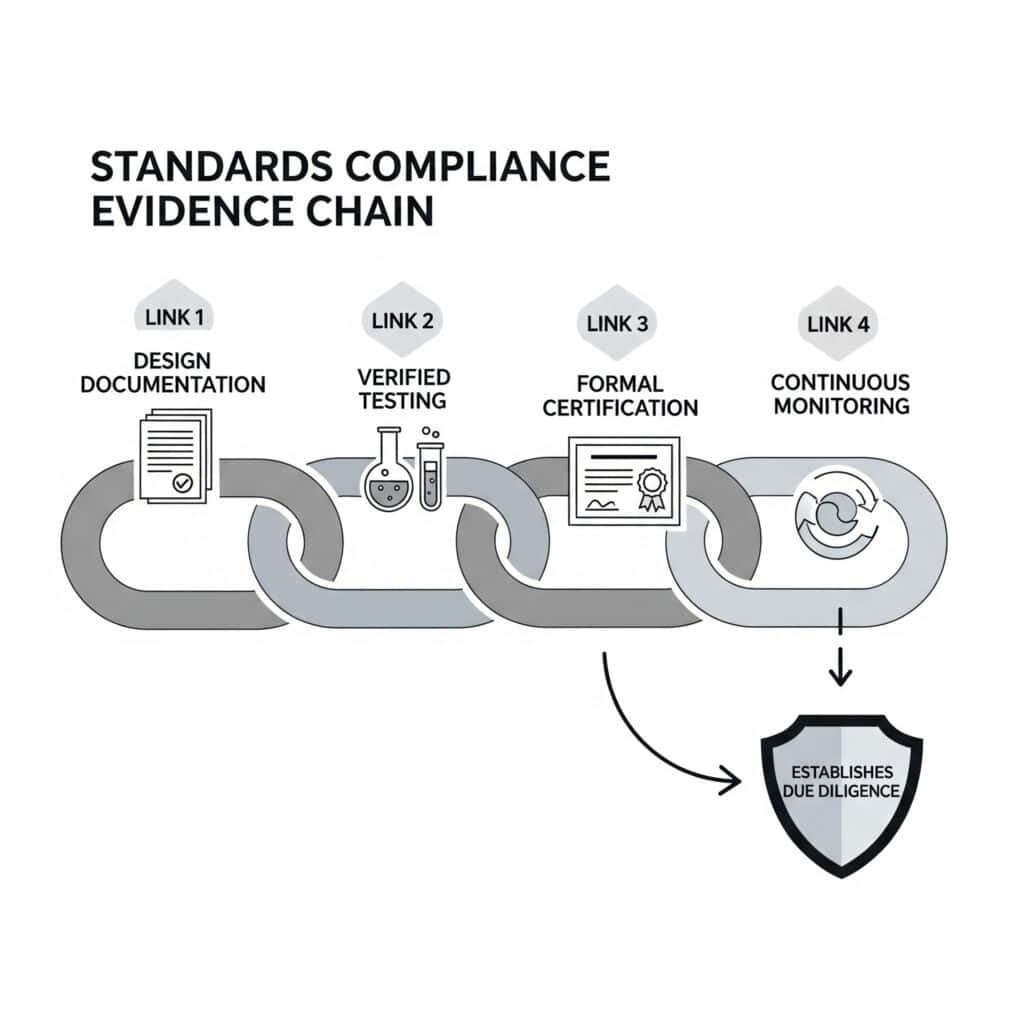
Pnömatik sistemler için etkili bir standartlara uygunluk kanıt zinciri dört temel unsurdan oluşur: belirli standart gereksinimlerine göre tasarım doğrulamasının kapsamlı dokümantasyonu, kalibre edilmiş ekipman ve tanıklık prosedürleri ile doğrulanmış test protokolleri, akredite üçüncü taraf değerlendirmesi yoluyla resmi sertifikasyon ve ürün yaşam döngüsü boyunca devam eden uyumluluğu izleyen sürekli izleme sistemleri. Bu zincir gerekli özeni gösterir ve sorumluluk taleplerine karşı savunmada belirleyici olabilir.
Pnömatik Sistem Gereksinimlerinin Standartlarla Eşleştirilmesi
Uyumluluğun temeli, sistem gereksinimlerinin belirli standartlarla net bir şekilde eşleştirilmesidir:
Pnömatik Sistemler için Standart Eşleme
| Sistem Yönü | Uygulanabilir Standartlar | Temel Gereksinimler | Gerekli Belgeler |
|---|---|---|---|
| Basınçlı Ekipman Güvenliği | ISO 4414, ASME B&PV Kodu | İzin verilen maksimum çalışma basıncı, güvenlik faktörleri, basınç testi | Tasarım hesaplamaları, malzeme sertifikaları, test raporları |
| Kontrol Sistemi Güvenliği | ISO 138494, IEC 62061 | Performans Seviyesi (PL) veya Güvenlik Bütünlüğü Seviyesi (SIL), hata toleransı | Risk değerlendirmesi, devre doğrulama, bileşen sertifikaları |
| Elektrikli Bileşenler | IEC 60204, NFPA 79 | Yalıtım, topraklama, elektrik çarpmasına karşı koruma | Elektrik şemaları, yalıtım testleri, toprak sürekliliği testleri |
| Tehlikeli Ortamlar | ATEX Direktifi, NEC 500 | Patlamaya karşı koruma yöntemleri, sıcaklık sınıflandırmaları | Bölge sınıflandırması, bileşen sertifikaları, kurulum doğrulaması |
| Çevresel Koşullar | IEC 60529, MIL-STD-810 | Giriş koruması, sıcaklık aralığı, titreşim direnci | Çevresel test raporları, IP sertifikası, iklim testi |
Yakın tarihli bir dava, bir gıda işleme ortamında arızalanan bir pnömatik sistemle ilgiliydi. Üretici ISO 4414'e uygunluk iddiasında bulunmuş ancak tasarımda belirli madde gerekliliklerinin nasıl karşılandığını gösteren belgeler sunamamıştır. Mahkeme, ayrıntılı bir gereklilik izlenebilirlik matrisi olmadan yalnızca uyumluluk iddiasında bulunmanın gerekli özeni göstermek için yetersiz olduğuna karar verdi.
Tasarım Doğrulama Dokümantasyonu
Tasarım doğrulaması, uyumluluk kanıt zincirinin ilk halkasını oluşturur:
Tasarım Doğrulama Dokümantasyon Gereklilikleri
| Doğrulama Öğesi | Dokümantasyon Türü | Teknik İçerik | Yasal Önem |
|---|---|---|---|
| Gereksinimlerin İzlenebilirliği | Gereksinimler Matrisi | Her bir standart maddenin tasarım özellikleriyle eşleştirilmesi | Kapsamlı standartların dikkate alındığını gösterir |
| Tasarım Hesaplamaları | Mühendislik Analizi | Güvenlik faktörleri, basınç değerleri, çevrim ömrü hesaplamaları | Tasarımda teknik durum tespiti yapıldığını kanıtlar |
| Risk Değerlendirmesi | ISO 12100 Analizi | Tehlike tanımlama, risk tahmini, risk azaltma önlemleri | Öngörülebilir risklerin ele alındığını gösterir |
| Tasarım İncelemeleri | İnceleme Raporları | Tasarım uygunluğunun bağımsız olarak doğrulanması | Uygunluk iddialarının akran doğrulamasını sağlar |
| Malzeme Seçimi | Malzeme Özellikleri | Uyumluluk, güç, çevresel direnç | Uygun malzeme seçim sürecini gösterir |
| Simülasyon Sonuçları | FEA/CFD Raporları | Stres analizi, akış modelleme, termal analiz | Kritik parametrelerin gelişmiş doğrulamasını gösterir |
Malzeme uyumsuzluğu nedeniyle arızalanan bir pnömatik sistemle ilgili bir anlaşmazlıkta, uyumluluk testi ve çevresel maruziyet analizi de dahil olmak üzere kapsamlı malzeme seçim belgelerini muhafaza eden üretici, tasarım sürecinde gerekli özeni göstererek sorumluluk iddialarına karşı başarılı bir şekilde savunma yaptı.
Test Protokolü Doğrulaması
Test protokolleri uyumluluğa ilişkin ampirik kanıt sağlar:
Test Kanıtı Gereklilikleri
| Test Türü | Protokol Gereklilikleri | Dokümantasyon Unsurları | Doğrulama Yöntemleri |
|---|---|---|---|
| Prototip Testi | Standartları referans alan yazılı test planları | Test kurulumu, prosedürler, kabul kriterleri | Bağımsız tanık, video belgeleme |
| Üretim Testleri | Belgelendirilmiş test prosedürleri | Başarılı/başarısız kriterleri, test ekipmanı özellikleri | İstatistiksel süreç kontrolü, kalibrasyon kayıtları |
| Tip Testi | Özel standart gereksinimlerine göre test | Ham verilerle eksiksiz test raporları | Akredite laboratuvar sertifikası |
| Tahribatlı Testler | Tanımlanmış arıza kriterleri | Fotoğrafik kanıtlar, ölçüm verileri | Malzeme analiz raporları |
| Saha Testleri | In-situ test protokolleri | Çevresel koşullar, operasyonel parametreler | Üçüncü taraf doğrulaması |
| Hızlandırılmış Ömür Testi | Gerçek dünya koşullarıyla korelasyon | Zaman sıkıştırma hesaplamaları, arıza analizi | İstatistiksel geçerlilik belgeleri |
Uygun test dokümantasyonunun önemi, bir üreticinin pnömatik bileşenlerinin tehlikeli ortamlar için derecelendirildiğini iddia ettiği bir vakada vurgulanmıştır. Bir sistem arızası endüstriyel bir kazaya yol açtığında, soruşturma test yapılırken test ekipmanının kalibrasyonunun süresinin dolduğunu ve test prosedürlerinin standart gerekliliklerden saptığını ortaya çıkarmıştır. Mahkeme, geçersiz test prosedürlerinin uygunluk kanıt zincirini kırdığına karar verdi.
Belgelendirme Dokümantasyonu
Resmi sertifikasyon, uyumluluğun üçüncü taraflarca onaylanmasını sağlar:
Sertifikasyon Kanıt Gereksinimleri
| Sertifikasyon Türü | İhraç Makamı | Gerekli Belgeler | Bakım Gereklilikleri |
|---|---|---|---|
| Bileşen Sertifikasyonu | Onaylanmış Kuruluşlar, UL, CSA | Belirli standartları referans alan sertifikalar | Yenileme dokümantasyonu, değişiklik yönetimi |
| Kalite Sistem Belgelendirmesi | ISO 9001 Tescil Kuruluşları | Denetim raporları, uygunsuzluk çözümleri | Gözetim denetim kayıtları, yönetim incelemeleri |
| Ürün Tip Onayı | Endüstri Belgelendirme Kuruluşları | Tip inceleme sertifikaları, teknik dosyalar | Periyodik yeniden belgelendirme, değişiklik onayları |
| Personel Sertifikasyonu | Mesleki Kuruluşlar | Eğitim kayıtları, yetkinlik değerlendirmeleri | Sürekli eğitim dokümantasyonu |
| Süreç Sertifikasyonu | Uzmanlaşmış Belgelendirme Kuruluşları | Süreç doğrulama kayıtları, yeterlilik çalışmaları | Süreç izleme verileri, yeniden doğrulama kayıtları |
| Öz Beyan | Üretici firma | Standartlar listesine uygunluk beyanı | Teknik dosya bakımı, değişiklik kontrol kayıtları |
Tıbbi cihazlar için pnömatik bileşenler üreten bir üretici, bir hasta yaralanmasının ardından sorumluluk iddialarına karşı, kendi sorumluluklarını destekleyen kapsamlı bir teknik dosya hazırlayarak başarılı bir şekilde savunma yapmıştır. CE işareti5. Dosya, her bir temel gereksinimin nasıl karşılandığını, doğrulandığını ve ürün değişiklikleri yoluyla nasıl korunduğunu gösteren ayrıntılı sertifikasyon belgelerini içeriyordu.
Sürekli İzleme Sistemleri
Devam eden uygunluk takibi kanıt zincirini tamamlar:
Sürekli İzleme Kanıt Gereksinimleri
| İzleme Unsuru | İzleme Yöntemleri | Gerekli Belgeler | Yasal Uygunluk |
|---|---|---|---|
| Ürün Performansı | Saha performans takibi | İstatistiksel analiz, trend raporları | Devam eden uygunluk doğrulamasını gösterir |
| Müşteri Geri Bildirimi | Şikâyet işleme sistemi | Şikayet kayıtları, çözüm belgeleri | Potansiyel sorunlara karşı duyarlılık gösterir |
| Üretim Süreci | İstatistiksel Süreç Kontrolü | Kontrol çizelgeleri, yeterlilik çalışmaları | Spesifikasyonlar dahilinde tutarlı üretimi kanıtlar |
| Tasarım Değişiklikleri | Değişim yönetim sistemi | Etki analizi, yeniden doğrulama kayıtları | Değişiklikler yoluyla uyumluluğun sürdürüldüğünü gösterir |
| Saha Olayları | Olay soruşturma süreci | Kök neden analizi, düzeltici faaliyetler | Saha sorunlarının ele alınmasında gerekli özeni gösterir |
| Mevzuat Güncellemeleri | Standart izleme süreci | Boşluk analizi, uygulama planları | Gelişen gereksinimlerin farkında olduğunu gösterir |
Önemli bir davada, endüstriyel ekipmanlar için pnömatik kontrol sistemleri üreticisi, bir sistem arızasının ardından sorumluluk talepleriyle karşı karşıya kaldı. Arızaya rağmen, diğer kurulumlarda benzer potansiyel sorunları tespit eden, düzeltici eylemleri uygulayan ve geri çağırma bildirimlerine yanıt vermeyen davacı da dahil olmak üzere tüm müşterileri bilgilendirmeye çalışan sağlam bir izleme sistemi göstererek sorumluluğu başarılı bir şekilde sınırlandırdılar. Bu proaktif izleme kanıtı, sorumluluk riskini önemli ölçüde azaltmıştır.
Savunulabilir Bir Teknik Dosya Oluşturmak
Kapsamlı bir teknik dosya, uyumluluk kanıt zincirinin tüm unsurlarını entegre eder:
Yasal Savunma için Teknik Dosya Yapısı
Ürün Tanımlaması ve Açıklaması
- Detaylı teknik özellikler
- Kullanım amacı ve sınırlamalar
- Sistem sınırları ve arayüzleri
- Bileşen tanımlama ve tedarikStandartlara Uygunluk Dokümantasyonu
- Standartların uygulanabilirlik değerlendirmesi
- Madde madde uyumluluk belgeleri
- Boşluk analizi ve gerekçeler
- Uygulanabilir olduğunda alternatif yöntemlerTasarım Dokümantasyonu
- Tasarım hesaplamaları ve analizleri
- Malzeme özellikleri ve gerekçeleri
- Risk değerlendirmeleri ve hafifletmeler
- Tasarım inceleme kayıtlarıDoğrulama ve Geçerleme
- Test planları ve prosedürleri
- Ham verileri içeren test raporları
- Simülasyon raporları
- Doğrulama protokolleri ve sonuçlarıÜretim Kontrolleri
- Üretim süreci özellikleri
- Kalite kontrol prosedürleri
- Muayene yöntemleri ve kriterleri
- Uygunsuzlukların ele alınmasıPazar Sonrası Gözetim
- Saha izleme prosedürleri
- Şikâyet işleme süreçleri
- Olay inceleme yöntemleri
- Düzeltici faaliyet prosedürleriDeğişim Yönetimi
- Değişiklik kontrol prosedürleri
- Etki değerlendirme yöntemleri
- Yeniden validasyon gereklilikleri
- Müşteri bildirim süreçleri
Örnek Olay İncelemesi: Pnömatik Sistem Uyum Anlaşmazlığı
Endüstriyel bir pres için kullanılan bir pnömatik kontrol sistemi, operatörün yaralanmasıyla sonuçlanan bir işyeri kazasına karışmıştır. Üretici, güvenlik standartlarına uymadığı iddiasına dayanan sorumluluk talepleriyle karşı karşıya kaldı.
Kanıt Zinciri Analizi:
Tasarım Doğrulama:
- Üretici ISO 12100 uyarınca kapsamlı risk değerlendirmesini sürdürdü
- ISO 13849-1'e göre Performans Seviyesi belirleme PL=d gereksinimini gösterdi
- Devre doğrulama belgeleri, tanılama özellikli çift kanallı mimariyi göstermiştir
- Eksik: Pnömatik bileşen arıza hariç tutma için özel hesaplamaKanıtların Test Edilmesi:
- Akredite laboratuvar tarafından kontrol sisteminin tip testi
- Elektrikli bileşenler için belgelenmiş hata enjeksiyon testi
- Eksik: Pnömatik bileşen arıza modlarının belgelenmiş testiSertifika:
- Uygunluk Beyanı ile CE işareti
- Kalite yönetim sistemi için ISO 9001 sertifikası
- Eksik: Güvenlikle ilgili pnömatik bileşenler için spesifik sertifikasyonSürekli İzleme:
- Saha performans takip sistemi yürürlükte
- Düzeltici faaliyetlerle birlikte incelenen önceki benzer olaylar
- Saha verilerine dayalı olarak uygulanan tasarım değişiklikleri
- Eksik: Bu spesifik riskin tespit edildiğine ve ele alındığına dair kanıt
Mahkeme Bulgusu:
Mahkeme, üreticinin genel olarak sağlam bir uyumluluk sistemine sahip olmasına rağmen, pnömatik bileşen doğrulamasındaki spesifik boşluğun kanıt zincirinde kopuk bir halka oluşturduğunu tespit etmiştir. Üretici, kazaya neden olan arıza moduna özgü gerekli özeni tam olarak gösteremediği için kısmen sorumlu bulundu.
Bu vaka, bir uyumluluk kanıt zincirinin ancak en zayıf halkası kadar güçlü olduğunu ve etkili bir yasal savunma için sistemin tüm yönlerini kapsayan kapsamlı bir dokümantasyonun şart olduğunu göstermektedir.
Sonuç: Önleyici Hukuk Stratejilerinin Uygulanması
Patent ihlali, ürün sorumluluğu ve standartlara uygunluğa ilişkin yasal çerçevelerin teknik yönlerinin anlaşılması, pnömatik sistem üreticilerinin etkili önleyici stratejiler uygulamasını sağlar. Şirketler bu alanları proaktif bir şekilde ele alarak hem dava riskini azaltabilir hem de anlaşmazlıklar ortaya çıktığında konumlarını güçlendirebilirler.
Temel Önleyici Stratejiler
Patent Risk Yönetimi
- Sistematik çalışma özgürlüğü analizleri uygulayın
- Tasarımla ilgili kararları teknik gerekçelerle belgeleyin
- Bağımsız yaratımı gösteren kapsamlı geliştirme kayıtlarının tutulması
- Üçüncü taraf patent bildirimlerini ele almak için net prosedürler oluşturunÜrün Sorumluluğunun Önlenmesi
- FMEA ve FTA metodolojilerini tasarım süreçlerine entegre etme
- Belgelendirilmiş risk değerlendirmeleri ile sağlam tasarım inceleme prosedürleri uygulamak
- Açık uyarılar içeren kapsamlı kullanıcı talimatları geliştirin
- Kanıtları koruyan olay inceleme prosedürleri oluşturunStandartlara Uygunluk Yönetimi
- Standart izlenebilirlik matrislerinin oluşturulması ve sürdürülmesi
- Standart gereksinimlerine göre resmi tasarım doğrulama süreçlerini uygulamak
- Uygun dokümantasyon ile kapsamlı test protokolleri oluşturun
- Devam eden uyumluluk için sürekli izleme sistemleri geliştirmek
Bu teknik çerçeveleri yasal risk yönetimine uygulayarak, pnömatik sistem üreticileri maliyetli anlaşmazlıklara maruz kalma risklerini önemli ölçüde azaltabilir ve dava açıldığında daha güçlü savunma pozisyonları oluşturabilirler.
Pnömatik Sistem Hukuki İhtilafları Hakkında SSS
Patent ihlali iddialarına karşı savunma yapmak için hangi belgeler tutulmalıdır?
Aşağıdakileri içeren kapsamlı tasarım geliştirme kayıtları tutun: tarihli tasarım konseptleri ve yinelemeleri, dikkate alınan alternatif tasarımlar, tasarım kararları için teknik gerekçeler, geliştirme sırasında incelenen önceki teknikler, bağımsız geliştirme kanıtları ve faaliyete geçme özgürlüğü analizleri. Bu kayıtlar geliştirme ile eşzamanlı olarak oluşturulmalı, uygun şekilde tarihlendirilmeli ve güvenli, kurcalanmaya karşı korumalı bir sistemde muhafaza edilmelidir. Buna ek olarak, kalifiye danışmanlardan alınan her türlü patent izni görüşünün kayıtlarını ve potansiyel olarak sorunlu patentler tespit edilmişse her türlü tasarım aşma çabasının belgelerini muhafaza edin.
Üreticiler gelişen standartlara uyumu nasıl etkili bir şekilde belgeleyebilir?
İlgili standart güncellemelerini takip eden ve değişiklikler meydana geldiğinde boşluk analizleri gerçekleştiren bir standart izleme sistemi uygulayın. Belirli ürün özelliklerini standart gerekliliklerle eşleştiren ve her bir gerekliliğin nasıl karşılandığını açık bir şekilde belgeleyen bir standart uyumluluk matrisi bulundurun. Her standart revizyonu için resmi bir etki değerlendirmesi yapın ve belgeleyin, gerekli tasarım veya süreç değişikliklerini uygulayın, uygun doğrulamayı gerçekleştirin ve teknik dosyayı buna göre güncelleyin. Üretim sırasında geçerli olan standartlara uygunluğu göstermek için bu belgelerin tüm sürümlerini saklayın.
Karmaşık pnömatik sistem arızalarında sorumluluğu paylaştırmanın en etkili yolu nedir?
En etkili yaklaşım birden fazla teknik analiz metodolojisini bir araya getirmektedir. Katkıda bulunan tüm potansiyel faktörleri belirlemek için kapsamlı bir Hata Ağacı Analizi (FTA) ile başlayın. Her bir faktörün göreceli etkisini değerlendirmek için Hata Modu ve Etkileri Analizi (FMEA) ile devam edin. Her bir önemli faktörü kök nedenine kadar izlemek için 5-Neden yöntemini uygulayın. Ardından bu teknik bulguları tasarım kararları, üretim süreçleri, kurulum prosedürleri, bakım faaliyetleri ve kullanıcı operasyonlarına dayalı belirli sorumluluklarla eşleştirin. Bu çok yöntemli yaklaşım, yasal incelemeye dayanabilecek sorumluluk paylaşımı için savunulabilir bir teknik temel sağlar.
-
İhlal eden cihaz bir patent talebinin gerçek kapsamına girmese bile mahkemelerin bir tarafı patent ihlalinden sorumlu bulmasına izin veren bir ABD patent hukuku ilkesi olan eşdeğerler doktrininin yasal bir açıklamasını sağlar. ↩
-
Bir patent sahibinin, önceki tekniğin üstesinden gelmek için patent kovuşturması sırasında daraltılan istem unsurları için eşdeğerlik doktrinini kullanmasını engelleyen, kovuşturma geçmişi estoppelinin (veya dosya ambalajı estoppelinin) yasal ilkesini detaylandırır. ↩
-
Bir sistemin arızasının bir dizi mantıksal adımla kök nedenlerine kadar izlendiği yukarıdan aşağıya, tümdengelimli bir arıza analizi olan Hata Ağacı Analizine (FTA) kapsamlı bir genel bakış sunar. ↩
-
Performans Seviyelerinin (PL) belirlenmesi de dahil olmak üzere kontrol sistemlerinin güvenlikle ilgili parçalarının tasarımı ve entegrasyonu için ilkeler hakkında güvenlik gereksinimleri ve rehberlik sağlayan ISO 13849 standardını açıklar. ↩
-
Avrupa Ekonomik Alanı (EEA) içinde satılan belirli ürünler için zorunlu bir uygunluk işareti olan ve ürünün AB sağlık, güvenlik ve çevre koruma gerekliliklerini karşıladığını belgeleyen CE işaretini açıklar. ↩
