
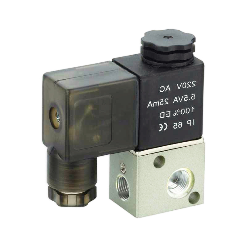
Are you experiencing pressure drops, slow system response, or premature valve failures in your pneumatic systems? These problems often stem from improper valve selection, costing thousands in downtime and repairs. Selecting the right pneumatic control valve is the key to solving these issues.
The perfect pneumatic control valve must match your system’s flow requirements (Cv value), have appropriate center position functionality for your application’s safety needs, and meet the durability standards for your operating frequency. Proper selection requires understanding flow coefficients, control functions, and life expectancy testing.
I remember helping a food processing plant in Wisconsin last year that was replacing valves every 3 months due to improper selection. After analyzing their system and selecting valves with appropriate Cv values and center positions, their maintenance costs dropped by 78% and production efficiency increased by 15%. Let me share what I’ve learned over my 15+ years in the pneumatic industry.
Зміст
- Understanding and Converting Cv Values for Proper Flow Matching
- How to Use Decision Trees for Center Position Function Selection
- High-frequency Valve Life Testing Standards and Longevity Prediction
How Do You Calculate and Convert Cv Values for Pneumatic Valve Selection?
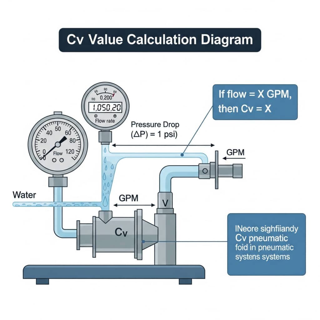
When selecting pneumatic valves, understanding flow capacity through Cv values1 ensures your system maintains proper pressure and response time.
The Cv value (flow coefficient) represents the flow capacity of a valve, indicating the volume of water in US gallons that will flow through the valve in one minute with a pressure drop of 1 psi. For pneumatic systems, this value helps determine if a valve can handle your required air flow without excessive pressure drop.
Understanding Flow Coefficient Basics
The flow coefficient (Cv) is fundamental to proper valve sizing. It represents how efficiently a valve passes fluid, with higher values indicating greater flow capacity. When selecting pneumatic valves, matching the Cv to your system requirements prevents:
- Pressure drops that reduce actuator force
- Slow system response times
- Excessive energy consumption
- Premature component failure
Conversion Methods Between Different Flow Coefficients
Several flow coefficient systems exist globally, and converting between them is essential when comparing valves from different manufacturers:
Cv to Kv Conversion
Kv is the European flow coefficient measured in m³/h:
Kv = 0.865 × Cv
Cv to Sonic Conductance (C) Conversion
Sonic conductance (C)2 is measured in dm³/(s·bar):
C = 0.0386 × Cv
Cv to Effective Orifice Area Conversion
The effective orifice area (S) in mm²:
S = 0.271 × Cv
Practical Conversion Table
| Cv Value | Kv Value | Sonic Conductance (C) | Effective Area (mm²) | Typical Application |
|---|---|---|---|---|
| 0.1 | 0.0865 | 0.00386 | 0.0271 | Small precision actuators |
| 0.5 | 0.4325 | 0.0193 | 0.1355 | Small cylinders, grippers |
| 1.0 | 0.865 | 0.0386 | 0.271 | Medium cylinders |
| 2.0 | 1.73 | 0.0772 | 0.542 | Large cylinders |
| 5.0 | 4.325 | 0.193 | 1.355 | Multiple actuator systems |
| 10.0 | 8.65 | 0.386 | 2.71 | Main supply lines |
Flow Calculation Formula for Pneumatic Systems
To determine the required Cv value for your application, use this formula for compressed air:
For subsonic flow (P₂/P₁ > 0.5):
Cv = Q / (22.67 × P₁ × √(1 – (ΔP/P₁)²))
Where:
- Q = Flow rate (SCFM at standard conditions)
- P₁ = Inlet pressure (psia)
- ΔP = Pressure drop (psi)
For sonic flow (P₂/P₁ ≤ 0.5):
Cv = Q / (22.67 × P₁ × 0.471)
Real-World Application Example
Last month, I helped a manufacturing client in Germany who was experiencing slow cylinder movement despite having adequate pressure. Their 40mm bore cylinders required faster cycling times.
Step 1: We calculated their required flow rate at 42 SCFM
Step 2: With a supply pressure of 87 psia (6 bar) and allowing a 15 psi pressure drop
Step 3: Using the subsonic flow formula: Cv = 42 / (22.67 × 87 × √(1 – (15/87)²)) = 0.22
By replacing their valves with Bepto valves having a Cv of 0.3 (providing a safety margin), their cycle times improved by 35%, solving their production bottleneck.
Which Center Position Function Should You Choose for Your Pneumatic System?
The center position of a directional control valve determines how your pneumatic system behaves during neutral states or power loss, making it critical for safety and functionality.
The ideal center position function depends on your application’s safety requirements, energy efficiency needs, and operational characteristics. Options include closed center (pressure hold), open center (pressure release), tandem center (A&B blocked), and float center (A&B connected to exhaust).
Understanding Valve Center Positions
Directional control valves, particularly 5/3 (5-port, 3-position) valves3, offer different center position configurations that determine system behavior when the valve is in its neutral state:
Closed Center (All Ports Blocked)
- Maintains pressure on both sides of the actuator
- Holds position under load
- Prevents movement during power loss
- Increases system rigidity
Open Center (P to T Connected)
- Relieves pressure from the supply line
- Reduces energy consumption during idle periods
- Allows for manual movement of actuators
- Common in energy-saving applications
Tandem Center (A&B Blocked, P to T Connected)
- Holds actuator position
- Relieves supply pressure
- Balances position holding with energy savings
- Good for vertical load applications
Float Center (A&B Connected to T)
- Allows free movement of the actuator
- Minimal resistance to external forces
- Used in applications requiring free movement in neutral
- Common in applications with manual positioning
Decision Tree for Center Position Selection
To simplify your selection process, follow this decision tree:
Is position holding under load critical?
– Yes → Go to 2
– No → Go to 3Is energy efficiency during idle periods important?
– Yes → Consider Tandem Center
– No → Choose Closed CenterIs free movement desirable when the valve is not actuated?
– Yes → Choose Float Center
– No → Go to 4Is supply pressure relief important?
– Yes → Choose Open Center
– No → Reconsider application requirements
Application-Specific Recommendations
| Application Type | Recommended Center Position | Reasoning |
|---|---|---|
| Vertical load holding | Closed Center or Tandem Center | Prevents drift due to gravity |
| Energy-sensitive systems | Open Center or Tandem Center | Reduces compressed air consumption |
| Safety-critical applications | Typically Closed Center | Maintains position during power loss |
| Systems with frequent manual adjustment | Float Center | Allows easy manual positioning |
| High-cycle rate applications | Application-specific | Depends on cycle requirements |
Case Study: Center Position Selection
A packaging equipment manufacturer in France was experiencing drift issues with their vertical actuators during emergency stops. Their existing valves had float centers, causing packages to drop during power interruptions.
After analyzing their system, I recommended switching to tandem center valves from Bepto. This change:
- Eliminated the drift problem completely
- Maintained their energy efficiency requirements
- Improved overall system safety
- Reduced product damage by 95%
The solution was so effective that they’ve since standardized on this valve configuration for all their vertical load applications.
How Do High-Frequency Valve Life Tests Predict Real-World Performance?
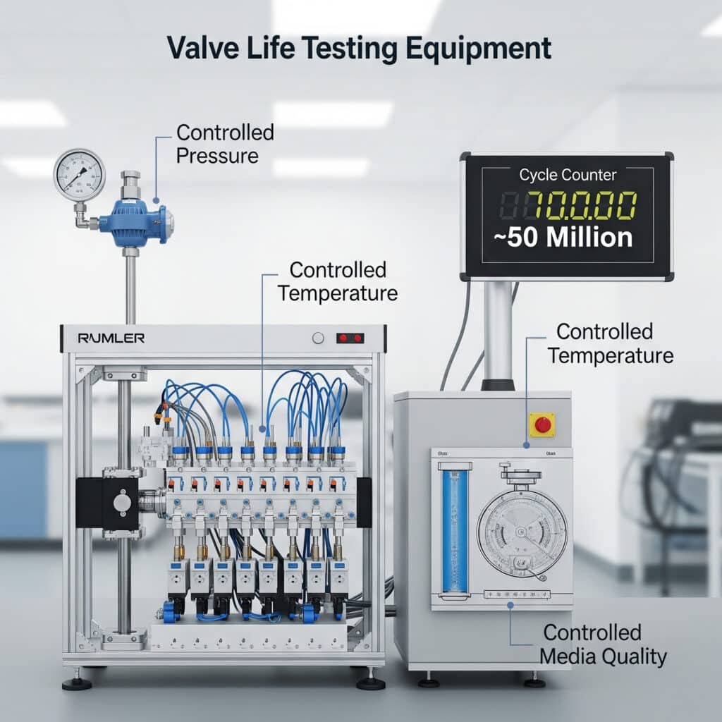
High-frequency valve life testing provides critical data for selecting valves in demanding applications where reliability and longevity are paramount.
Pneumatic valve life testing involves cycling valves at accelerated rates under controlled conditions to predict real-world longevity. Standard tests typically measure performance to 50-100 million cycles, with factors like operating pressure, temperature, and media quality affecting results.
Industry Standard Testing Protocols
High-frequency valve life testing follows several established standards:
ISO 199734 Standard
This international standard specifically addresses pneumatic fluid power valve testing:
- Defines test procedures for various valve types
- Establishes standard test conditions
- Provides reporting requirements for consistent comparison
- Requires specific failure criteria definitions
NFPA T2.6.1 Standard
The National Fluid Power Association standard focuses on:
- Endurance testing methods
- Performance degradation measurement
- Environmental condition specifications
- Statistical analysis of results
Key Testing Parameters
Effective valve life testing must control and monitor these critical parameters:
Cycling Frequency
- Typically 5-15 Hz for standard valves
- Up to 30+ Hz for specialized high-frequency valves
- Must balance test speed with realistic operation
Робочий тиск
- Tests at multiple pressure points (typically minimum, nominal, and maximum)
- Pressure fluctuation monitoring during cycling
- Pressure recovery time measurement
Temperature Conditions
- Ambient temperature control
- Temperature rise monitoring during operation
- Thermal cycling for certain applications
Air Quality
- Defined contamination levels (per ISO 8573-1)
- Moisture content control
- Oil content specification
Life Expectancy Prediction Models
Test results are used in mathematical models to predict real-world performance:
Weibull Analysis5
This statistical method:
- Predicts failure rates based on test data
- Identifies likely failure modes
- Establishes confidence intervals for life expectancy
- Helps determine appropriate maintenance intervals
Acceleration Factors
Converting test results to real-world expectations requires:
- Duty cycle adjustments
- Environmental factor corrections
- Application-specific stress calculations
- Safety margin application
Comparative Life Test Results Table
| Тип клапана | Test Frequency | Test Pressure | Cycles to First Failure | Estimated Real-World Life | Common Failure Mode |
|---|---|---|---|---|---|
| Standard Solenoid | 10 Hz | 6 bar | 20 million | 5-7 years at 2 cycles/min | Seal wear |
| High-Speed Solenoid | 25 Hz | 6 bar | 50 million | 8-10 years at 5 cycles/min | Solenoid burnout |
| Pilot-Operated | 8 Hz | 6 bar | 35 million | 10-12 years at 1 cycle/min | Pilot valve failure |
| Mechanical Valve | 5 Hz | 6 bar | 15 million | 15+ years at 0.5 cycles/min | Mechanical wear |
| Bepto High-Frequency | 30 Hz | 6 bar | 100 million | 12-15 years at 10 cycles/min | Seal wear |
Practical Application of Test Results
Understanding test results helps in proper valve selection:
Calculate your application’s annual cycles:
Daily cycles × operating days per year = annual cyclesDetermine required valve life:
Expected system life in years × annual cycles = total required cyclesApply a safety factor:
Total required cycles × 1.5 (safety factor) = design requirementSelect valve with appropriate test results:
Choose a valve with test results exceeding your design requirement
I recently worked with an automotive parts manufacturer in Michigan who was replacing valves every 6 months in their high-cycle testing equipment. By analyzing their 15 million cycles per year requirement and selecting Bepto high-frequency valves tested to 100 million cycles, we extended their valve replacement interval to over 3 years, saving them approximately $45,000 annually in maintenance costs and downtime.
Conclusion
Selecting the right pneumatic control valve requires understanding flow coefficients (Cv values), choosing appropriate center position functionality, and considering valve life expectancy based on standardized testing. By applying these principles, you can optimize system performance, reduce maintenance costs, and improve operational reliability.
FAQs About Pneumatic Valve Selection
What is the Cv value in pneumatic valves and why is it important?
The Cv value is a flow coefficient that indicates how much flow a valve permits with a specific pressure drop. It’s important because it determines whether a valve can provide adequate flow for your application without causing excessive pressure drop, which would reduce system performance and efficiency.
How do I convert between Cv and other flow coefficients?
Convert Cv to Kv (European standard) by multiplying by 0.865. Convert Cv to sonic conductance (C) by multiplying by 0.0386. Convert Cv to effective orifice area by multiplying by 0.271. These conversions allow comparison between valves specified with different flow coefficient systems.
What happens if I select a valve with too small of a Cv value?
A valve with too small of a Cv value will create a flow restriction, causing pressure drop, slow actuator movement, reduced force output, and potentially overheating the valve due to high-velocity flow. This results in poor system performance and potentially shortened valve life.
How does the center position of a pneumatic valve affect system operation?
The center position determines how the valve behaves when not actively shifted to a working position. It affects whether actuators hold position, drift, or move freely; whether system pressure is maintained or relieved; and how the system responds during power loss or emergency situations.
What factors affect pneumatic valve life in high-frequency applications?
The main factors affecting valve life in high-frequency applications include operating pressure, air quality (particularly cleanliness, moisture, and lubrication), ambient and operating temperatures, cycle frequency, and duty cycle. Proper selection based on standardized life testing helps ensure reliability.
How can I estimate the required Cv value for my pneumatic application?
Estimate the required Cv value by determining your maximum flow rate in SCFM, your available supply pressure, and your acceptable pressure drop. Then apply the formula: Cv = Q / (22.67 × P₁ × √(1 – (ΔP/P₁)²)) for subsonic flow, where Q is flow rate, P₁ is inlet pressure, and ΔP is acceptable pressure drop.
-
Provides a technical definition of the Flow Coefficient (Cv), an imperial measurement that represents a valve’s capacity to allow fluid flow, which is a critical parameter for proper valve sizing. ↩
-
Explains Sonic Conductance (C), the ISO 6358 standard for rating pneumatic valve flow based on choked flow conditions, and provides conversion formulas and comparisons to the more traditional Cv value. ↩
-
Describes the standard industry convention for naming directional control valves (e.g., 2/2, 3/2, 5/2, 5/3), where the first number indicates the number of ports and the second number indicates the number of positions. ↩
-
Offers an overview of the ISO 19973 standard, which specifies methods for testing the operational characteristics of pneumatic directional control valves to ensure consistent performance reporting. ↩
-
Details the principles of Weibull analysis, a versatile statistical method commonly used in reliability engineering to model failure times, analyze life data, and predict the life expectancy of components. ↩
