Are you struggling to find pneumatic components that can withstand extreme military environments? Many engineers discover too late that commercial-grade cylinders fail catastrophically when subjected to battlefield conditions, leading to mission-critical system failures and potentially life-threatening situations.
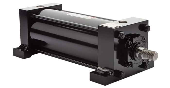
Military-grade cilindri pneumatici are engineered to withstand extreme conditions through specialized designs that meet rigorous standards like GJB150.18 shock testing (requiring survival of 100g acceleration pulses), EMI shielding enclosures that provide 80-100dB of electromagnetic interference protection, and comprehensive “three-proof” coating systems that resist salt spray for 1,000+ hours while maintaining functionality in temperature ranges from -55°C to +125°C.
Indice dei contenuti
- How Does GJB150.18 Shock Testing Ensure Battlefield Reliability?
- What Makes EMI Shielding Essential for Modern Military Systems?
- Which Anti-corrosion Coating Systems Provide True Military-grade Protection?
- How Are Rodless Cylinders Used in Aircraft Carrier Catapult Systems?
- Conclusione
- FAQs About Military-Grade Pneumatic Cylinders
How Does GJB150.18 Shock Testing Ensure Battlefield Reliability?
Military equipment must withstand extreme mechanical shocks from explosions, weapon firing, rough terrain, and hard landings that would destroy standard commercial components.
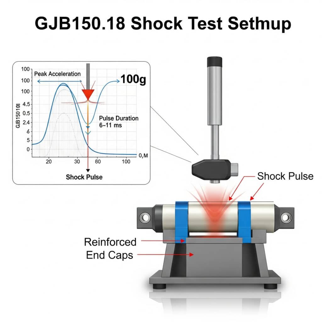
The GJB150.18 shock test standard1 subjects pneumatic cylinders to precisely controlled acceleration pulses reaching 100g (981 m/s²) with durations of 6-11ms across multiple axes. Military-grade cylinders must maintain full functionality after these tests, requiring specialized internal designs with reinforced end caps, shock-absorbing cushions, and secured internal components that prevent catastrophic failures during battlefield impacts.

Key Test Parameters
| Parametro | Requirement | Commercial Equivalent | Military Advantage |
|---|---|---|---|
| Peak Acceleration | 100g (981 m/s²) | 15-25g (147-245 m/s²) | 4-6× higher impact resistance |
| Pulse Duration | 6-11ms (half-sine) | 15-30ms (when tested) | Simulates sharper battlefield impacts |
| Number of Impacts | 18 total (3 per direction, 6 directions) | 3-6 total (when tested) | Ensures multi-axis durability |
| Functional Testing | During and after shock | After shock only (when tested) | Verifies real-time operation |
Naval defense contractors have documented cases where industrial-grade cylinders in missile loading systems experienced internal component failures after experiencing shocks of only 30g during rough seas. After redesigning with military-grade cylinders qualified to GJB150.18, these systems maintained perfect functionality even during simulated battle conditions with shocks exceeding 80g.
Critical Design Elements
Reinforced End Caps
– Increased thickness: 2.5-3× commercial standards
– Enhanced threading engagement: 150-200% more thread depth
– Additional retention features: Safety wire holes, locking mechanismsInternal Component Securing
– Piston-to-rod connection: Mechanical locks vs. press-fits
– Thread locking compounds: Military-spec anaerobic adhesives
– Redundant retention: Secondary mechanical locks for critical componentsShock-Absorbing Features
– Enhanced cushioning: Extended cushion length (200-300% of commercial)
– Progressive cushioning: Multi-stage deceleration profiles
– Cushion material: Specialized polymers with higher energy absorptionStructural Reinforcements
– Thicker cylinder walls: 150-200% of commercial thickness
– Gusseted mounting features: Reinforced mounting points
– Rod diameter increase: 130-150% of commercial equivalents
Shock Failure Analysis
| Failure Mode | Commercial Failure Rate | Military-Grade Mitigation | Effectiveness |
|---|---|---|---|
| End Cap Ejection | High (primary failure) | Mechanical locks, increased thread engagement | >99% reduction |
| Piston-Rod Separation | Alto | Mechanical interlocking, welded assembly | >99% reduction |
| Seal Extrusion | Medio | Reinforced seals, anti-extrusion rings | 95% reduction |
| Bearing Deformation | Medio | Hardened materials, increased support area | Riduzione 90% |
| Mounting Failure | Alto | Gusseted mounts, increased bolt pattern | >99% reduction |
What Makes EMI Shielding Essential for Modern Military Systems?
Modern battlefield environments are saturated with electromagnetic signals that can disrupt or damage sensitive electronic systems, requiring specialized protection for pneumatic components with electronic interfaces.
Military-grade pneumatic cylinders with electronic components require EMI shielding enclosures that provide 80-100dB of attenuation across frequencies from 10kHz to 10GHz. These specialized designs incorporate Faraday cage principles2 using conductive materials, specialized gaskets, and filtered connections to prevent both electromagnetic interference and potential signal interception that could compromise operational security.

EMI Threat Sources and Impacts
| EMI Source | Gamma di frequenza | Field Strength | Potential Impact on Pneumatic Systems |
|---|---|---|---|
| Radar Systems | 1-40 GHz | 200+ V/m | Sensor malfunction, control disruption |
| Radio Communications | 30 MHz-3 GHz | 50-100 V/m | Signal corruption, false triggering |
| EMP Weapons3 | DC-1 GHz | 50,000+ V/m | Complete electronic failure, data corruption |
| Power Generation | 50/60 Hz | High magnetic fields | Sensor interference, position errors |
| Lightning/Static | DC-10 MHz | Extreme transients | Component damage, system reset |
Missile defense system manufacturers have documented cases where position feedback cylinders experienced intermittent errors during radar operation. Investigation revealed that radar pulses were inducing currents in the sensor wiring, causing position reporting errors of up to 15mm. By implementing comprehensive EMI shielding with 85dB attenuation, these interference issues were completely eliminated, achieving position accuracy within 0.05mm even during active radar operation.
Critical Design Elements
Material Selection
– Conductive housing materials (aluminum, steel, conductive composites)
– Surface conductivity enhancement (plating, conductive coatings)
– Permeability considerations for magnetic shieldingSeam and Joint Treatment
– Continuous electrical contact at all seams
– Conductive gasket selection based on compression set and galvanic compatibility
– Fastener spacing (typically λ/20 at highest frequency)Penetration Management
– Filtered electrical connections (feedthrough capacitors, PI filters)
– Waveguide-below-cutoff designs for necessary openings
– Conductive glands for cable entriesGrounding Strategy
– Single-point vs. multi-point grounding based on frequency
– Ground plane implementation
– Bonding resistance specifications (<2.5 mΩ typical)
Confronto delle prestazioni dei materiali
| Materiale | Shielding Effectiveness | Weight Impact | Corrosion Resistance | Migliore applicazione |
|---|---|---|---|---|
| Aluminum (6061-T6) | 60-80 dB | Basso | Good with treatment | General purpose, weight-sensitive |
| Stainless Steel (304) | 70-90 dB | Alto | Eccellente | Corrosive environments, durability |
| MuMetal | 100+ dB (magnetic) | Medio | Moderato | Low-frequency magnetic fields |
| Conductive Silicone | 60-80 dB | Molto basso | Eccellente | Gaskets, flexible interfaces |
| Copper Foil | 80-100 dB | Basso | Poor without coating | Highest conductivity needs |
Naval fire control systems with pneumatic actuators require a careful balance between corrosion resistance and EMI shielding. Military engineers often select 316 stainless steel enclosures with silver-plated beryllium copper gaskets, achieving 92dB average attenuation while maintaining full functionality in a salt-spray environment.
Which Anti-corrosion Coating Systems Provide True Military-grade Protection?
Military pneumatic systems must operate in extreme environments ranging from desert heat to arctic cold, saltwater exposure, chemical threats, and abrasive conditions that rapidly destroy standard commercial finishes.
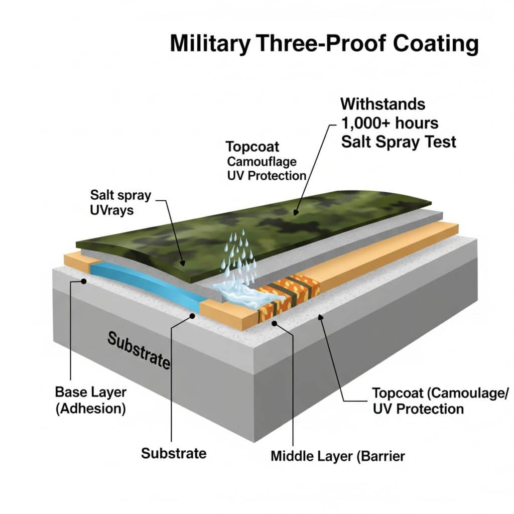
Military-grade “three-proof” coating systems for pneumatic cylinders combine multiple specialized layers: a chromate conversion or phosphate base layer for adhesion and initial corrosion resistance, a high-build epoxy or polyurethane middle layer providing chemical and moisture barrier properties, and a UV-resistant topcoat that adds camouflage, low-reflectivity, and additional chemical protection, together withstanding 1,000+ hours of salt spray testing.

Protection Categories
Moisture/Corrosion Resistance
– Salt spray resistance (1,000+ hours per ASTM B1174)
– Humidity resistance (95% RH at elevated temperatures)
– Immersion capability (freshwater and saltwater)Resistenza chimica
– Fuel and hydraulic fluid compatibility
– Decontamination solution resistance
– Lubricant compatibilityEnvironmental Durability
– UV radiation resistance
– Temperature extremes (-55°C to +125°C)
– Abrasion and impact resistance
Military deployment evaluations in the Middle East have compared standard industrial cylinders with military-grade units featuring comprehensive coating systems. After just three months in the desert environment with salt-laden air and sand abrasion, commercial cylinders showed significant corrosion and seal degradation. The military-grade cylinders with three-proof coatings remained fully functional after two years in the same environment, with only minor cosmetic wear.
Layer Function and Performance
| Layer | Primary Function | Thickness Range | Key Properties | Application Method |
|---|---|---|---|---|
| Pretreatment | Surface preparation, initial corrosion protection | 2-15μm | Adhesion promotion, conversion coating | Chemical immersion, spray |
| Prime Coat | Adhesion, corrosion inhibition | 25-50μm | Barrier protection, inhibitor release | Spray, electrodeposition |
| Intermediate Coat | Build thickness, barrier properties | 50-100μm | Chemical resistance, impact absorption | Spray, dip |
| Top Coat | UV protection, appearance, specific properties | 25-75μm | Color/gloss control, specialized resistance | Spray, electrostatic |
Mid-Layer Performance Comparison
| Coating Type | Salt Spray Resistance | Resistenza chimica | Intervallo di temperatura | Migliore applicazione |
|---|---|---|---|---|
| Epoxy (High-Build) | 1,000-1,500 hrs | Eccellente | -40°C to +120°C | Uso generale |
| Poliuretano | 800-1,200 hrs | Molto buono | -55°C to +100°C | Low temperature |
| Zinc-Rich Epoxy | 1,500-2,000 hrs | Buono | -40°C to +150°C | Corrosive environments |
| CARC | 1,000-1,500 hrs | Eccellente | -55°C to +125°C | Chemical threat areas |
| Fluoropolymer | 2,000+ hrs | Eccezionale | -70°C to +200°C | Extreme environments |
For missile launcher systems with pneumatic actuators, military engineers have implemented specialized coating systems with zinc-rich epoxy primer and CARC topcoat. These systems maintain full functionality after 2,000+ hours of salt spray testing and demonstrate resistance to chemical warfare agent simulants.
Environmental Performance Comparison
| Environment | Commercial Coating Life | Military-Grade Life | Performance Ratio |
|---|---|---|---|
| Desert (Hot/Dry) | 6-12 months | 5-7+ years | 5-7× |
| Tropical (Hot/Humid) | 3-9 months | 4-6+ years | 8-12× |
| Marine (Salt Exposure) | 2-6 months | 4-5+ years | 10-15× |
| Arctic (Extreme Cold) | 12-24 months | 6-8+ years | 4-6× |
| Battlefield (Combined) | 1-3 months | 3-4+ years | 12-16× |
How Are Rodless Cylinders Used in Aircraft Carrier Catapult Systems?
Aircraft carrier catapult systems5 represent one of the most demanding applications for pneumatic technology, requiring exceptional power, precision, and reliability.
Aircraft carrier catapult systems utilize specialized high-pressure rodless cylinders as critical components in the aircraft launch mechanism. These cylinders generate the tremendous force needed to accelerate fighter jets from 0 to 165 knots (305 km/h) within just 2-3 seconds across a deck length of approximately 90 meters, subjecting the pneumatic components to extreme pressures, temperatures, and mechanical stresses.

Key Advantages of Rodless Design
| Caratteristica | Benefit in Catapult Systems | Comparison to Rod Cylinders |
|---|---|---|
| Space Efficiency | Entire stroke fits within deck length | Rod cylinder would require 2× installation space |
| Weight Distribution | Balanced moving mass | Rod cylinder has asymmetric mass distribution |
| Acceleration Capability | Optimized for rapid acceleration | Rod cylinder limited by rod buckling concerns |
| Sealing System | Specialized for high-speed operation | Standard seals would fail at launch speeds |
| Force Transmission | Direct coupling to shuttle | Complex linkages would be required with rod design |
Typical Performance Parameters
| Parametro | Specifiche | Engineering Challenge |
|---|---|---|
| Pressione di esercizio | 200-350 bar (2,900-5,075 psi) | Extreme pressure containment |
| Peak Force | 1,350+ kN (300,000+ lbf) | Force transmission without distortion |
| Acceleration Rate | Up to 4g (39 m/s²) | Controlled acceleration profile |
| Cycle Speed | 45-60 seconds between launches | Rapid pressure recovery |
| Operational Reliability | 99.9%+ success rate required | Elimination of failure modes |
| Vita utile | 5,000+ launches between overhauls | Wear minimization at high speeds |
Critical Design Elements
Sealing Technology
– Composite PTFE-based seals with metal energizers
– Multi-stage sealing systems with pressure staging
– Active cooling channels for thermal managementCarriage Design
– Aerospace-grade aluminum or titanium construction
– Integrated energy absorption systems
– Low-friction bearing interfacesCylinder Body Construction
– Autofrettaged high-strength steel construction
– Stress-optimized profile to minimize weight
– Corrosion-resistant internal coatingsControl Integration
– Real-time position feedback systems
– Velocity and acceleration monitoring
– Pressure profiling capabilities
Environmental Factors and Mitigations
| Environmental Factor | Challenge | Engineering Solution |
|---|---|---|
| Salt Spray Exposure | Extreme corrosion potential | Multi-layer coating systems, stainless components |
| Temperature Variations | -30°C to +50°C operational range | Special sealing materials, thermal compensation |
| Deck Movement | Constant motion during operation | Flexible mounting systems, stress isolation |
| Vibration | Continuous shipboard vibration | Vibration dampening, secured components |
| Jet Fuel Exposure | Chemical attack on seals and coatings | Specialized chemical-resistant materials |
Conclusione
Military-grade pneumatic cylinders represent a specialized category of components engineered to withstand the extreme conditions encountered in defense applications. The rigorous shock testing requirements of GJB150.18, comprehensive EMI shielding designs, and advanced multi-layer coating systems all contribute to creating pneumatic solutions that deliver reliable performance in the most demanding environments. The application of rodless cylinders in aircraft carrier catapult systems demonstrates how specialized pneumatic technology can meet even the most extreme performance requirements.
FAQs About Military-Grade Pneumatic Cylinders
What is the typical cost premium for military-grade pneumatic cylinders?
Military-grade pneumatic cylinders typically cost 3-5 times more than their commercial counterparts. However, the lifecycle cost analysis often shows military-grade components to be more economical when considering the total ownership cost, as they typically offer 5-10 times longer service life in harsh environments and significantly reduced failure rates.
Can commercial cylinders be upgraded to meet military specifications?
While some commercial cylinders can be modified to enhance their performance, true military-grade specifications typically require fundamental design changes that aren’t feasible as upgrades. For mission-critical applications, purpose-built military-grade cylinders are strongly recommended rather than attempting to upgrade commercial models.
What documentation is typically required for military-grade pneumatic components?
Military-grade pneumatic components require extensive documentation including material certifications with full traceability, process control records, test reports, first article inspection reports, certificates of conformance to applicable military standards, and quality system compliance documentation.
How do temperature extremes affect military cylinder design?
Military pneumatic cylinders must function across temperature ranges from -55°C to +125°C, requiring specialized seal compounds, materials with matching thermal expansion coefficients, and lubricants that maintain appropriate viscosity across the entire temperature range. These temperature extremes typically necessitate specialized testing in environmental chambers.
How is EMI shielding verified for military pneumatic systems?
EMI shielding verification follows rigorous testing protocols defined in standards like MIL-STD-461G. Testing typically includes shielding effectiveness measurements in specialized chambers, transfer impedance testing for conductive gaskets and seams, and system-level radiated and conducted emissions/susceptibility testing.
-
Provides details on MIL-STD-810, the U.S. Military Standard for environmental engineering, specifically its test methods for simulating mechanical shocks that equipment may experience during handling, transport, and use. ↩
-
Explains the physics behind a Faraday cage, an enclosure made of a conductive material that blocks external static and non-static electric fields, which is the fundamental principle behind EMI shielding. ↩
-
Describes the characteristics of an Electromagnetic Pulse (EMP), a short burst of electromagnetic energy that can be generated by a nuclear explosion or a non-nuclear weapon, and its damaging effects on electronic equipment. ↩
-
Details the ASTM B117 standard, a widely used and standardized test method for evaluating the corrosion resistance of coated samples in a salt spray or fog environment. ↩
-
Offers an explanation of the technology behind aircraft carrier catapults, including both traditional steam-powered systems and the modern Electromagnetic Aircraft Launch System (EMALS), which are used to accelerate aircraft to safe flying speeds. ↩


