Are you struggling with inconsistent pneumatic cylinder speeds or unexpected end-of-stroke impacts? These common problems often stem from a poor understanding of piston kinematics. Many engineers focus solely on force requirements while overlooking the critical motion parameters that determine system performance.
Piston kinematics1 directly impact pneumatic system performance through pressure-velocity relationships, acceleration limits, and cushioning requirements. Understanding these principles allows engineers to properly size components, predict actual motion profiles, and prevent premature failures in rodless cylinders and other pneumatic actuators.
In my 15+ years at Bepto working with pneumatic systems, I’ve seen countless cases where understanding these fundamental principles has helped customers solve persistent performance issues and extend equipment life by 3-5 times.
目次
- What Pressure Do You Actually Need for Constant Speed Motion?
- How Do You Calculate the Maximum Possible Acceleration in Pneumatic Cylinders?
- Why Does Cushioning Time Matter and How Is It Calculated?
- 結論
- FAQs About Piston Kinematics in Pneumatic Systems
What Pressure Do You Actually Need for Constant Speed Motion?
Many engineers simply apply the maximum available pressure to their pneumatic systems, but this approach is inefficient and can lead to jerky motion, excessive wear, and wasted energy.
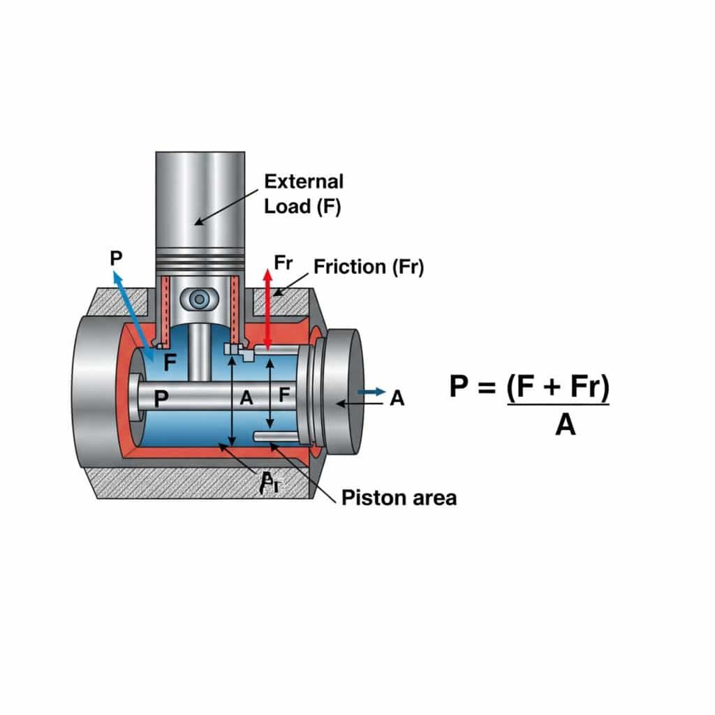
The pressure required for constant speed motion in a pneumatic cylinder is calculated using P = (F + Fr)/A, where P is pressure, F is the external load force, Fr is the friction resistance, and A is the piston area. This calculation ensures smooth, efficient operation without excessive pressure that wastes energy and accelerates component wear.

Understanding the pressure requirements for constant speed motion has practical implications for system design and operation. Let me break this down into actionable insights.
Factors Affecting Pressure Requirements for Constant Speed
The pressure needed to maintain constant velocity depends on several factors:
| ファクター | Impact on Pressure Requirement | Practical Consideration |
|---|---|---|
| External Load | Direct linear relationship | Varies with orientation and external forces |
| 摩擦 | Adds to required pressure | Changes with seal wear and lubrication |
| Piston Area | Inversely proportional | Larger bore = lower pressure requirement |
| Air Supply Restrictions | Pressure drops in lines/valves | Size components for minimal pressure drop |
| Back Pressure | Opposes motion | Consider exhaust flow capacity |
Calculating Minimum Pressure for Stable Motion
To determine the minimum pressure needed for stable motion:
- Calculate the force required to overcome the external load
- Add the friction force (typically 3-20% of maximum force)
- Divide by the effective piston area
- Add a stability factor (typically 10-30%)
For example, in a 40mm bore rodless cylinder with a 10kg load and 15% friction:
| パラメータ | 計算 | Result |
|---|---|---|
| Load Force | 10kg × 9.81m/s² | 98.1N |
| Friction Force | 15% of max force at 6 bar | ~45N |
| Total Force | 98.1N + 45N | 143.1N |
| Piston Area | π × (0.02m)² | 0.00126m² |
| Minimum Pressure | 143.1N ÷ 0.00126m² | 113,571 Pa (1.14 bar) |
| With 20% Stability Factor | 1.14 bar × 1.2 | 1.37 bar |
Real-World Application: Energy Savings Through Pressure Optimization
Last year, I worked with Robert, a production engineer at a furniture manufacturing plant in Michigan. His automated assembly line used rodless cylinders operating at the full 6 bar supply pressure, regardless of load.
After analyzing his application, we determined that most movements only required 2.5-3 bar for stable operation. By installing proportional pressure regulators, we reduced air consumption by 40% while maintaining the same cycle time. This saved approximately $12,000 annually in energy costs while reducing seal wear and extending maintenance intervals.
Velocity-Pressure Relationship in Real Systems
In practice, the relationship between pressure and velocity isn’t perfectly linear due to:
- 流量制限: Valve and port sizing affects maximum achievable velocity
- Compressibility effects: Air is compressible, causing acceleration lags
- Stick-slip phenomena: Friction characteristics change with velocity
- Inertial effects: Mass acceleration requires additional force/pressure
How Do You Calculate the Maximum Possible Acceleration in Pneumatic Cylinders?
Understanding acceleration limits is crucial for preventing excessive shock, vibration, and premature component failure in pneumatic systems.
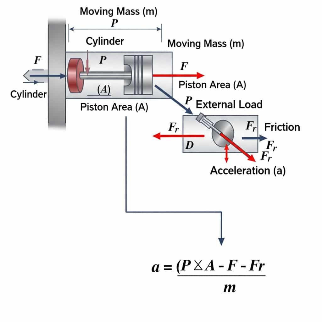
The maximum possible acceleration in a pneumatic cylinder is calculated using a = (P × A – F – Fr)/m, where a is acceleration, P is pressure, A is piston area, F is external load, Fr is friction resistance, and m is the moving mass. This equation defines the physical limits of how quickly a pneumatic actuator can start or stop motion.

The theoretical acceleration limits have significant practical implications for system design and component selection.
Derivation of the Acceleration Limit Equation
The acceleration limit equation comes from Newton’s Second Law2 (F = ma):
- The net force available for acceleration is: Fnet = Fpressure – Fload – Ffriction
- Fpressure = P × A
- Therefore: a = Fnet/m = (P × A – F – Fr)/m
Practical Acceleration Limits for Different Cylinder Types
Different cylinder designs have different practical acceleration limits:
| Cylinder Type | Typical Max Acceleration | Limiting Factors |
|---|---|---|
| Standard rod cylinder | 10-15 m/s² | Rod buckling, bearing loads |
| Rodless cylinder (magnetic) | 8-12 m/s² | Magnetic coupling strength |
| Rodless cylinder (mechanical) | 15-25 m/s² | Seal/bearing design, internal friction |
| Guide cylinder | 20-30 m/s² | Guide system rigidity, bearing capacity |
| Impact cylinder | 50-100+ m/s² | Specially designed for high acceleration |
Mass Considerations in Acceleration Calculations
When calculating acceleration, it’s critical to include all moving masses:
- Piston assembly: Includes piston, seals, and connecting elements
- Load mass: External load being moved
- Effective mass of moving air: Often negligible but relevant in high-speed applications
- Added mass due to mounting components: Brackets, sensors, etc.
I once helped a customer in France who was experiencing mysterious failures in his rodless cylinder system. The cylinder was sized correctly for the stated 15kg load, but was consistently failing after a few thousand cycles.
After investigating, we discovered he had neglected to account for the 12kg mass of the mounting plate and attachments. The actual moving mass was nearly double what he had calculated, causing acceleration forces that exceeded the cylinder’s design limits. After upgrading to a larger cylinder, the failures stopped completely.
Acceleration Control Methods
To control acceleration within safe limits:
- Flow control valves: Limit flow rate during initial movement
- Proportional valves: Provide controlled pressure ramp-up
- Multi-stage acceleration: Use stepped pressure increases
- Mechanical damping: Add external shock absorbers
- Electronic control: Use servo-pneumatic systems3 with acceleration feedback
Why Does Cushioning Time Matter and How Is It Calculated?
Proper end-of-stroke cushioning is essential for preventing impact damage, reducing noise, and extending the life of pneumatic cylinders. Understanding cushioning time helps engineers design systems that balance cycle time with component longevity.
Cushioning time in pneumatic cylinders is calculated using the equation t = √(2s/a), where t is time, s is cushioning stroke length, and a is deceleration. This time represents how long it takes to safely decelerate the moving mass before impact, which is critical for preventing damage to the cylinder and attached components.

Let’s explore the practical aspects of cushioning time calculations and their implications for system design.
The Physics Behind Pneumatic Cushioning
Pneumatic cushioning works through controlled air compression and restricted exhaust:
- As the piston enters the cushion chamber, the exhaust path is restricted
- The trapped air compresses, creating increasing back pressure
- This back pressure creates a counter force that decelerates the piston
- The deceleration profile depends on cushion design and adjustment
Calculating Optimal Cushioning Time
The optimal cushioning time balances impact prevention with cycle time efficiency:
| パラメータ | フォーミュラ | 例 |
|---|---|---|
| Cushioning Distance | Based on cylinder design | 15mm (typical for 40mm bore) |
| Required Deceleration | a = v²/(2s) | For v=0.5m/s, s=15mm: a = 8.33m/s² |
| Cushioning Time | t = √(2s/a) | t = √(2×0.015/8.33) = 0.06s |
| Pressure Build-up | P = P₀(V₀/V)^γ | Depends on cushion chamber geometry |
Factors Affecting Cushioning Performance
Several factors influence actual cushioning performance:
- Cushion seal design: Affects air leakage during cushioning
- Needle valve adjustment: Controls exhaust restriction rate
- Moving mass: Heavier loads require longer cushioning time
- Approach velocity: Higher speeds require longer cushion distance
- 動作圧力: Affects maximum counter force available
Cushioning Types and Their Applications
Different cushioning mechanisms are appropriate for different applications:
| クッションタイプ | 特徴 | ベストアプリケーション |
|---|---|---|
| Fixed cushioning | Simple, non-adjustable | Light loads, consistent operation |
| Adjustable cushioning | Tunable with needle valves | Varying loads, flexible applications |
| Self-adjusting cushioning | Adapts to different conditions | Changing speeds and loads |
| 外部ショックアブソーバー | High energy absorption | Heavy loads, high speeds |
| Electronic cushioning | Precisely controlled deceleration | Servo-pneumatic systems |
Case Study: Optimizing Cushioning in High-Cycle Applications
I recently worked with Thomas, a design engineer at an automotive components manufacturer in Germany. His assembly line used rodless cylinders operating at 45 cycles per minute, but was experiencing frequent seal failures and mounting bracket damage.
Analysis revealed that the cushioning time was too short for the moving mass, causing impact forces of nearly 3G at each end of stroke. By increasing the cushioning stroke from 12mm to 20mm and optimizing the needle valve settings, we extended the cushioning time from 0.04s to 0.07s.
This seemingly small change reduced impact forces by over 60%, eliminated the bracket damage completely, and extended seal life from 3 months to over a year—all while maintaining the required cycle time.
Practical Cushioning Adjustment Procedure
For optimal cushioning performance in rodless cylinders:
- Start with cushion valves fully open (minimum restriction)
- Gradually close the cushion valve until smooth deceleration is achieved
- Test with minimum and maximum expected loads
- Verify cushioning performance across the full speed range
- Listen for impact sounds that indicate insufficient cushioning
- Measure actual deceleration time to confirm calculations
結論
Understanding the principles of piston kinematics—from pressure requirements for constant speed to acceleration limits and cushioning time calculations—is essential for designing efficient, reliable pneumatic systems. By applying these principles to your rodless cylinder applications, you can optimize performance, reduce energy consumption, and significantly extend component life.
FAQs About Piston Kinematics in Pneumatic Systems
What pressure do I need for a specific cylinder speed?
The pressure needed depends on the load, friction, and cylinder area. Calculate it using P = (F + Fr)/A, where F is the external load force, Fr is friction resistance, and A is the piston area. For a typical rodless cylinder moving a 10kg load horizontally, you’ll need approximately 1.5-2 bar for stable motion at moderate speeds.
How fast can a pneumatic cylinder accelerate?
A pneumatic cylinder’s maximum acceleration is calculated using a = (P × A – F – Fr)/m. Typical rodless cylinders can achieve 10-25 m/s² acceleration depending on design. This translates to reaching a speed of 0.5 m/s in approximately 20-50 milliseconds under optimal conditions.
What factors limit the maximum speed of a rodless cylinder?
The maximum speed is limited by valve flow capacity, air supply volume, port sizing, cushioning capabilities, and seal design. Most standard rodless cylinders are designed for maximum speeds of 0.8-1.5 m/s, though specialized high-speed designs can reach 2-3 m/s.
How do I calculate the proper cushioning for my application?
Calculate proper cushioning by determining the kinetic energy (KE = ½mv²) of your moving load and ensuring your cushioning system can absorb this energy. The cushioning time should be calculated using t = √(2s/a), where s is cushion distance and a is the desired deceleration rate.
What happens if my pneumatic cylinder accelerates too quickly?
Excessive acceleration can cause mechanical stress on mounting components, premature seal wear, increased vibration and noise, potential load shifting or damage, and reduced system precision. It can also lead to jerky motion that affects product quality in precision applications.
How does load orientation affect the pressure required for movement?
Load orientation significantly impacts pressure requirements. Vertical loads moving against gravity require additional pressure to overcome gravitational force (P = F/A + Fg/A + Fr/A). Horizontal loads only need to overcome friction and inertia. Inclined loads fall between these extremes based on the sine of the angle.
-
Provides a foundational explanation of kinematics, the branch of mechanics that describes the motion of objects without considering the forces that cause the motion.
electronic input signal, enabling advanced pneumatic control. ↩ -
Details Newton’s Second Law (F=ma), the fundamental principle of physics that relates the force acting on an object to its mass and acceleration, which is the basis for all dynamic calculations. ↩
-
Describes servo-pneumatics, an advanced control technology that combines the power of pneumatics with the precision of closed-loop electronic control to achieve highly accurate positioning and motion profiles. ↩


