
De nachtmerrie van elke onderhoudsmonteur is onverwachte uitval van apparatuur. Wanneer machines op hun natuurlijke frequentie trillen, kan er binnen enkele minuten catastrofale schade optreden. Ik heb gezien hoe dit probleem bedrijven duizenden dollars aan stilstand kostte.
Trillingsresonantie1 treedt op wanneer een externe kracht overeenkomt met de natuurlijke frequentie van een systeem, waardoor versterkte trillingen ontstaan die apparatuur kunnen beschadigen. Het begrijpen en beheersen van dit fenomeen is essentieel voor het voorkomen van storingen en het verlengen van de levensduur van machines.
Ik zal u een kort verhaal vertellen. Vorig jaar belde een klant uit Duitsland me in paniek op. Hun productielijn was gestopt omdat een staafloze cilinder trilde hevig. Het probleem? Resonantie. Aan het eind van dit artikel zul je begrijpen hoe je soortgelijke problemen in je systemen kunt identificeren en voorkomen.
Inhoudsopgave
- Natuurlijke Frequentie Formule: Hoe kunt u de kwetsbare punten van uw systeem berekenen?
- Massa-veren model: Waarom is deze vereenvoudigde benadering zo waardevol?
- Optimalisatie dempingsverhouding: Welke experimenten leveren de beste resultaten op?
- Conclusie
- Veelgestelde vragen over vibratieresonantie
Natuurlijke Frequentie Formule: Hoe kunt u de kwetsbare punten van uw systeem berekenen?
De natuurlijke frequentie van uw apparatuur begrijpen is de eerste stap in het voorkomen van resonantieproblemen. Deze kritische waarde bepaalt wanneer uw systeem het meest kwetsbaar is voor trillingsproblemen.
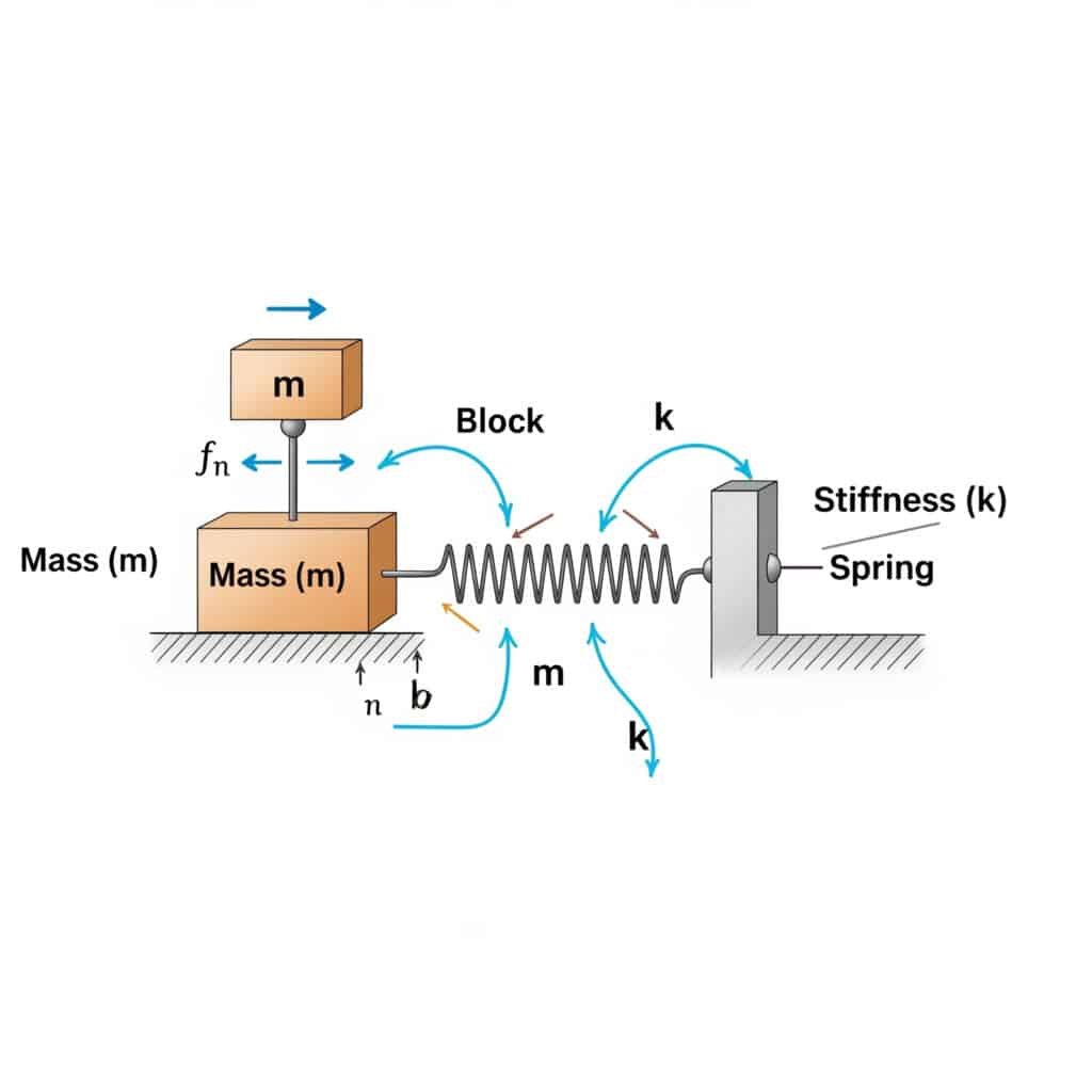
De natuurlijke frequentie2 (fn) van een systeem kan worden berekend met de formule: fn = (1/2π) × √(k/m), waarbij k de stijfheidscoëfficiënt is en m de massa. Deze berekening geeft aan bij welke frequentie je systeem zal resoneren als het wordt aangeslagen door bijpassende externe krachten.
Toen ik een productiefabriek in Zwitserland bezocht, merkte ik dat hun pneumatische cilinders zonder stangen het voortijdig begaven. Hun onderhoudsteam had de natuurlijke frequentie van hun opstelling niet berekend. Na toepassing van deze formule stelden we vast dat hun werksnelheid gevaarlijk dicht bij de natuurlijke frequentie van het systeem lag.
Praktische toepassingen van berekeningen van natuurlijke frequenties
De natuurlijke frequentieformule is niet alleen theoretisch, maar heeft ook directe toepassingen in verschillende industriële omgevingen:
- Uitrusting selecteren: Componenten kiezen met natuurlijke frequenties die ver van uw bedrijfsomstandigheden liggen
- Preventief onderhoud: Planning van inspecties op basis van trillingsrisicoprofielen
- Problemen oplossen: De hoofdoorzaak van onverwachte trillingen opsporen
Algemene eigenfrequentiewaarden voor industriële componenten
| Component | Typisch natuurlijk frequentiebereik (Hz) |
|---|---|
| Cilinders zonder stangen | 10-50 Hz |
| Montagebeugels | 20-100 Hz |
| Ondersteunende structuren | 5-30 Hz |
| Regelkleppen | 40-200 Hz |
Kritische factoren die de eigenfrequentie beïnvloeden
De berekening van de eigenfrequentie lijkt eenvoudig, maar verschillende factoren kunnen toepassingen in de praktijk bemoeilijken:
- Niet-uniforme massaverdeling: De meeste industriële componenten hebben geen perfect verdeelde massa
- Variabele stijfheid: Onderdelen kunnen verschillende stijfheid hebben in verschillende richtingen
- Aansluitpunten: De manier waarop componenten worden gemonteerd heeft een grote invloed op hun trillingskarakteristieken
- Temperatuur: Zowel de massa als de stijfheid kunnen veranderen met de temperatuur
Massa-veren model: Waarom is deze vereenvoudigde benadering zo waardevol?
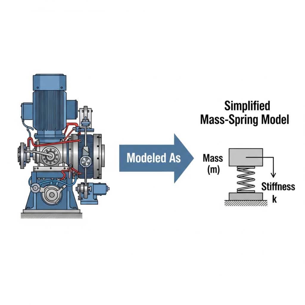
Het massa-veer model biedt een intuïtief raamwerk om complexe trillingssystemen te begrijpen. Het reduceert ingewikkelde machines tot basiselementen die ingenieurs gemakkelijk kunnen analyseren.
De massa-veer model3 vereenvoudigt trillingsanalyse door mechanische systemen voor te stellen als discrete massa's verbonden door veren. Met deze aanpak kunnen ingenieurs het gedrag van systemen voorspellen, potentiële resonantieproblemen identificeren en effectieve oplossingen ontwikkelen zonder complexe wiskunde.
Ik herinner me dat ik samenwerkte met een fabrikant van auto-onderdelen in Michigan die maar niet begreep waarom hun geleide cilinders zonder stang het begaven. Door hun systeem te modelleren als een eenvoudige massa-veer constructie, stelden we vast dat de montagebeugels als onbedoelde veren werkten, waardoor een resonantieconditie ontstond.
Reële systemen omzetten naar massa-veer-modellen
Om deze benadering toe te passen op uw apparatuur:
- De belangrijkste massa's identificeren: Bepaal welke componenten een significant gewicht bijdragen
- Veerelementen lokaliseren: Onderdelen vinden die energie opslaan en afgeven (echte veren, flexibele steunen, enz.)
- Kaartverbindingen: Documenteren hoe massa's en veren op elkaar inwerken
- Vereenvoudig: Combineer gelijksoortige elementen tot een hanteerbaar model
Soorten massa-veersystemen
| Type systeem | Beschrijving | Algemene toepassingen |
|---|---|---|
| Enkele DOF | Eén massa met één veer | Eenvoudige pneumatische cilinders |
| Multi-DOF | Meerdere massa's met meerdere veren | Complexe machines met meerdere componenten |
| Doorlopend | Oneindige DOF (vereist andere analyse) | Balken, platen en schalen |
Overwegingen voor geavanceerde modellering
Hoewel het basismodel van massa-veer waardevol is, maken verschillende verbeteringen het realistischer:
- Dempers toevoegen: Echte systemen hebben altijd energiedissipatie
- Rekening houden met niet-lineariteiten: Veren volgen niet altijd Wet van Hooke4 perfect
- Rekening houden met gedwongen trillingen: Externe krachten veranderen het gedrag van het systeem
- Inclusief koppelingseffecten: Beweging in één richting kan andere richtingen beïnvloeden
Optimalisatie dempingsverhouding: Welke experimenten leveren de beste resultaten op?
Demping is je beste verdediging tegen resonantieproblemen. Door proefondervindelijk de optimale dempingsverhouding te vinden, kun je de prestaties en betrouwbaarheid van het systeem drastisch verbeteren.
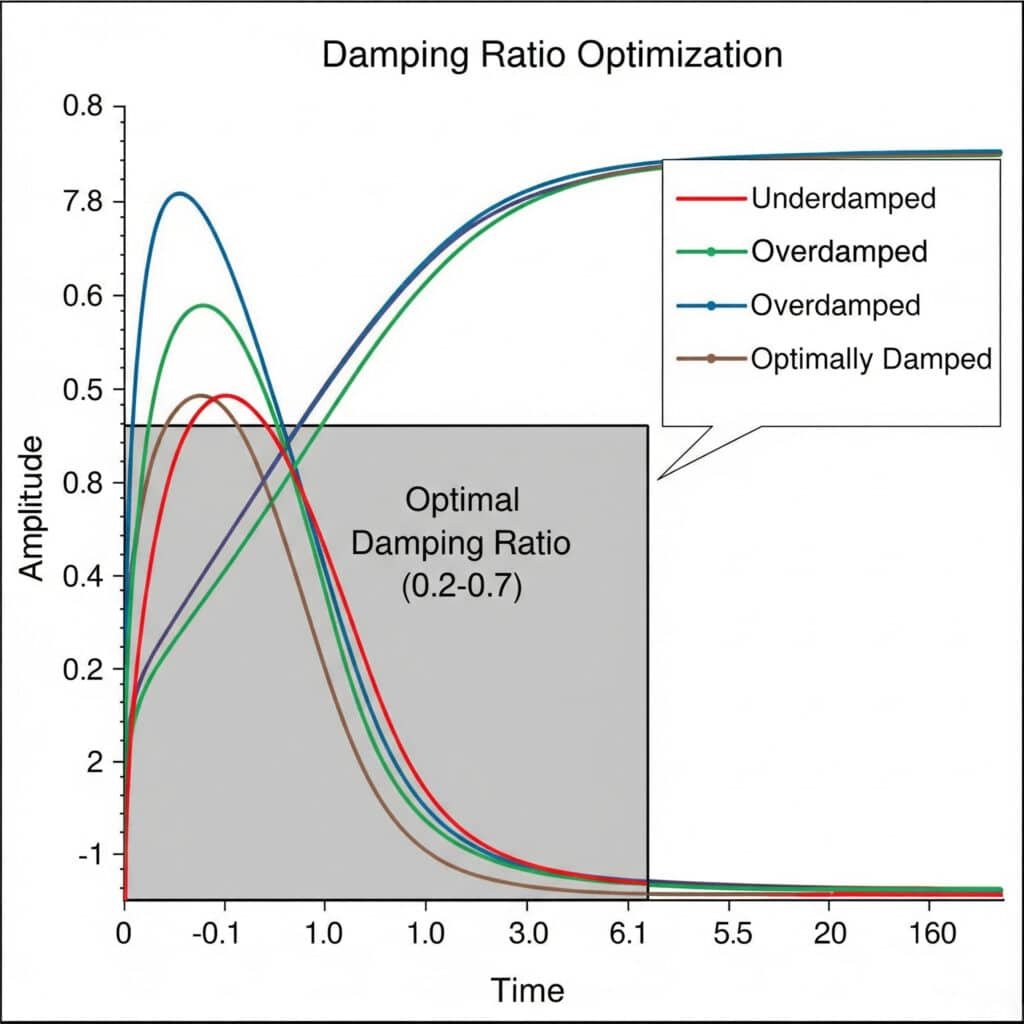
Dempingsverhouding5 Optimalisatie-experimenten omvatten het systematisch testen van verschillende dempingsconfiguraties om de ideale balans te vinden tussen trillingscontrole en systeemresponsiviteit. De optimale dempingsverhouding ligt meestal tussen 0,2 en 0,7 en biedt voldoende trillingsonderdrukking zonder overmatig energieverlies.
Vorige maand hielp ik een fabrikant van voedselverwerkingsapparatuur in Frankrijk bij het oplossen van hardnekkige trillingsproblemen in hun magnetische cilinders zonder stang. Door een reeks experimenten met de dempingsverhouding ontdekten we dat hun oorspronkelijke ontwerp een dempingsverhouding van slechts 0,05 had - veel te laag om resonantieproblemen te voorkomen.
Experimentele opstelling voor dempingsverhoudingen
Effectieve optimalisatie-experimenten voor demping uitvoeren:
- Basislijnmeting: Systeemrespons opnemen zonder extra demping
- Incrementeel testen: Dempingselementen toevoegen in gecontroleerde stappen
- Antwoordmeting: Meet amplitude, settlingtijd en frequentierespons
- Gegevensanalyse: Bereken de dempingsverhouding voor elke configuratie
- Validatie: Controleer de prestaties onder werkelijke bedrijfsomstandigheden
Vergelijking dempingstechnologieën
| Dempingstechnologie | Voordelen | Beperkingen | Typische toepassingen |
|---|---|---|---|
| Viskeuze dempers | Voorspelbare prestaties, temperatuurstabiel | Vereist onderhoud, potentiële lekken | Zware machines, precisieapparatuur |
| Wrijvingsdempers | Eenvoudig ontwerp, kosteneffectief | Slijtage na verloop van tijd, niet-lineair gedrag | Structurele ondersteuning, basismachines |
| Materiaal Demping | Geen bewegende delen, compact | Beperkt verstelbereik | Precisie-instrumenten, trillingsisolatie |
| Actieve demping | Aanpasbaar aan veranderende omstandigheden | Complex, vereist vermogen | Kritische toepassingen, apparatuur met variabele snelheid |
Demping optimaliseren voor verschillende bedrijfsomstandigheden
De ideale dempingsverhouding is niet universeel, maar hangt af van je specifieke toepassing:
- Snelle bewerkingen: Lagere dempingsverhoudingen (0,1-0,3) behouden het reactievermogen
- Precisietoepassingen: Hogere dempingsverhoudingen (0,5-0,7) zorgen voor stabiliteit.
- Systemen met variabele belasting: Adaptieve demping kan nodig zijn
- Temperatuurgevoelige omgevingen: Overweeg dempingsmaterialen met stabiele eigenschappen
Casestudie: Optimalisatie demping stangloze cilinders
Bij het optimaliseren van een dubbelwerkende cilinder zonder stang voor een verpakkingsmachine hebben we vijf verschillende dempingsconfiguraties getest:
- Standaard eindkussens: Dempingsverhouding = 0,12
- Verlengde kussens: Dempingsverhouding = 0,25
- Externe schokdempers: Dempingsverhouding = 0,41
- Composiet montagebeugels: Dempingsverhouding = 0,38
- Gecombineerde aanpak (3+4): Dempingsverhouding = 0,53
De gecombineerde aanpak leverde de beste prestaties en verminderde de trillingsamplitude met 78% terwijl de responstijden acceptabel bleven.
Conclusie
Inzicht in trillingsresonantie door middel van natuurlijke frequentieberekeningen, massa-veer-modellering en optimalisatie van de dempingsverhouding is cruciaal voor het voorkomen van storingen aan apparatuur. Door deze principes toe te passen kunt u de levensduur van machines verlengen, stilstand verminderen en de algehele systeemprestaties verbeteren.
Veelgestelde vragen over vibratieresonantie
Wat is trillingsresonantie in industriële apparatuur?
Trillingsresonantie treedt op wanneer een externe kracht overeenkomt met de natuurlijke frequentie van een systeem, waardoor versterkte trillingen ontstaan. In industriële apparatuur kan dit fenomeen leiden tot overmatige beweging, vermoeidheid van onderdelen en catastrofale storingen als er niet goed mee wordt omgegaan.
Hoe weet ik of mijn systeem last heeft van resonantie?
Zoek naar symptomen zoals onverklaarbare geluidstoenames, zichtbare trillingen bij specifieke snelheden, voortijdige defecten aan onderdelen en prestatievermindering die optreedt bij consistente werkingspunten. Tools voor trillingsanalyse kunnen resonantiecondities bevestigen.
Wat is het verschil tussen geforceerde trilling en resonantie?
Geforceerde trilling treedt op wanneer een externe kracht op een systeem inwerkt, terwijl resonantie de specifieke toestand is wanneer die forcerende frequentie overeenkomt met de natuurlijke frequentie van het systeem, wat resulteert in een versterkte respons. Alle resonantie gaat gepaard met gedwongen trillingen, maar niet alle gedwongen trillingen veroorzaken resonantie.
Hoe beïnvloedt het ontwerp van een staafloze pneumatische cilinder de trillingseigenschappen?
Het ontwerp van staafloze pneumatische cilinders - met hun bewegende slede, intern afdichtingssysteem en geleidingsmechanismen - creëert unieke trillingsuitdagingen. Het verlengde profiel werkt als een balk die kan buigen, de massa van de slede creëert traagheidskrachten en de afdichtingsbanden kunnen variabele wrijving introduceren.
Welke eenvoudige aanpassingen kunnen resonantie in bestaande apparatuur verminderen?
Voor bestaande apparatuur die resonantieproblemen ondervindt, kunt u overwegen om massa toe te voegen om de natuurlijke frequentie te wijzigen, externe dempers of schokdempers te installeren, de montagemethoden aan te passen om trillingsisolatie toe te voegen of de bedrijfssnelheden aan te passen om resonantiefrequenties te vermijden.
-
Biedt een fundamentele uitleg van mechanische resonantie, vaak met visuele voorbeelden, en laat zien hoe een kleine periodieke kracht oscillaties met een grote amplitude kan produceren in een systeem. ↩
-
Biedt een gedetailleerde blik op de fysica van natuurlijke frequentie, de specifieke frequentie waarbij een systeem neigt te oscilleren bij afwezigheid van een aandrijvende of dempende kracht. ↩
-
Legt de principes uit van het massa-veermodel, een fundamentele idealisering in de natuurkunde en techniek die wordt gebruikt om complexe systemen te analyseren die eenvoudige harmonische bewegingen vertonen. ↩
-
Details Wet van Hooke, een natuurkundig principe dat stelt dat de kracht die nodig is om een veer over een bepaalde afstand uit te rekken of in te drukken recht evenredig is met die afstand. ↩
-
Beschrijft de dempingsratio, een dimensieloze maat die bepaalt hoe oscillaties in een systeem vervallen na een verstoring, wat cruciaal is voor het beheersen van resonantie. ↩
