| Bore(mm) | 32 | 40 | 50 | 63 | 80 | 100 | 125 | 160 | 200 |
| Motion Pattern | Double Action | ||||||||
| Working Medium | Air | ||||||||
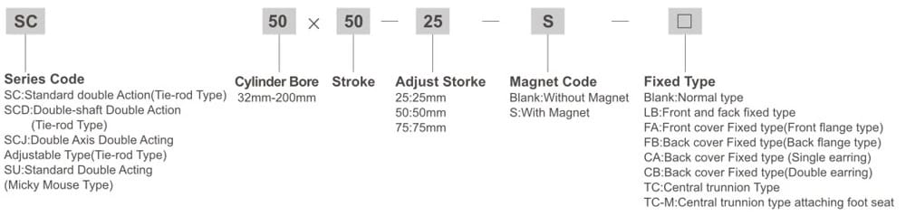
| Fixed Type | Normal type FA/Type FB/Type CA/Type CB/Type LB/Type TC/Type TC-M/ type | ||||||||
| Operating Voltage Range | 0.1~0.9kgf/cm2 | ||||||||
| Ensured Pressure Resistance | 1.35Mpa | ||||||||
| Operating Temperature Range | -5~70℃ | ||||||||
| Operating Speed Range | 30~800mm/s | ||||||||
| Buffer Type | Adjustable Buffer | ||||||||
| Buffer Stroke | 24 | 32 | |||||||
| Port Size | G1/8″ | G1/4″ | G3/8″ | G1/2″ | G3/4″ | ||||
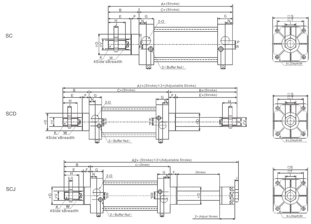
| Bore/Symbol | A | A1 | A2 | B | C | D | E | F | G | H | I | J | K |
| 32 | 140 | 187 | 182 | 47 | 93 | 26 | 32 | 15 | 27.5 | 22 | 17 | 6 | M10×1.25 |
| 40 | 142 | 191 | 185 | 49 | 93 | 32 | 34 | 15 | 27.5 | 24 | 17 | 7 | M12×1.25 |
| 50 | 150 | 207 | 196 | 57 | 93 | 36 | 42 | 15 | 27.5 | 32 | 24 | 8 | M16×1.5 |
| 63 | 153 | 210 | 199 | 57 | 96 | 36 | 42 | 15 | 27.5 | 32 | 24 | 8 | M16×1.5 |
| 80 | 182 | 257 | 242 | 75 | 107 | 47 | 54 | 21 | 33 | 40 | 26 | 10 | M20×1.5 |
| 100 | 188 | 263 | 248 | 75 | 108 | 47 | 54 | 21 | 33 | 40 | 26 | 10 | M20×1.5 |
| 125 | 203 | 291 | 265.5 | 88 | 115 | 52 | 68 | 20 | 38 | 54 | 41 | 9 | M27×2 |
| 160 | 293 | 352 | 332 | 113 | 126 | 62 | 88 | 25 | 38 | 72 | 55 | 16 | M36×2 |
| 200 | 244 | 362 | 342 | 118 | 126 | 62 | 88 | 30 | 38 | 72 | 55 | 16 | M36×2 |
| Bore/Symbol | L | M | N | O | P | Q | R | S | T | V | W | Z |
| 32 | M6×1 | 9.5 | 13.7 | G1/8″ | 3.5 | 7.5 | 7 | 45 | 33 | 12 | 10 | 21 |
| 40 | M6×1 | 9.5 | 13.5 | G1/4″ | 6 | 8.2 | 9 | 50 | 37 | 16 | 14 | 21 |
| 50 | M6×1 | 9.5 | 13.5 | G1/4″ | 8.5 | 8.2 | 9 | 62 | 47 | 20 | 17 | 23 |
| 63 | M8×1.25 | 9.5 | 13.5 | G3/8″ | 7 | 8.2 | 8.5 | 75 | 56 | 20 | 17 | 23 |
| 80 | M10×1.5 | 11.5 | 16.5 | G3/8″ | 10 | 9.5 | 14 | 94 | 70 | 25 | 22 | 29 |
| 100 | M10×1.5 | 11.5 | 16.5 | G1/2″ | 11 | 9.5 | 14 | 112 | 84 | 25 | 22 | 29 |
| 125 | M12×1.75 | 16 | 20 | G1/2″ | 14 | 6.5 | 14 | 136 | 104 | 32 | 27 | 42.5 |
| 160 | M16×2 | 15 | 20 | G3/4″ | 15 | 5 | 15 | 174 | 134 | 40 | 36 | 68 |
| 200 | M16×2 | 15 | 20 | G3/4″ | 15 | 3 | 15 | 214 | 163 | 40 | 36 | 68 |