
Factory floors grind to a halt when cylinders fail. Engineers panic as production lines stop without warning. Most people never understand the elegant physics that make these workhorses of automation function.
A cylinder works by using compressed air or hydraulic fluid to create pressure differential across a piston surface, converting fluid pressure into linear mechanical force according to Pascal’s Law1 (F = P × A), enabling controlled linear motion for industrial automation.
Last week, I received an urgent call from Roberto, a plant manager in Italy whose bottling line had been down for 6 hours. His maintenance team was replacing cylinders randomly without understanding why they failed. I walked them through the basic operating principles over video call, and they identified the real problem – contaminated air supply. The line was running again in 30 minutes, saving them $15,000 in lost production.
Table of Contents
- What Is the Basic Operating Principle of a Cylinder?
- How Do the Internal Components Work Together?
- What Role Does Pressure Play in Cylinder Operation?
- How Do Different Cylinder Types Work?
- How Do Control Systems Make Cylinders Work?
- What Forces and Calculations Govern Cylinder Operation?
- How Do Environmental Factors Affect Cylinder Operation?
- What Common Problems Prevent Proper Cylinder Operation?
- How Do Modern Cylinders Integrate with Automation Systems?
- Conclusion
- FAQs About How Cylinders Work
What Is the Basic Operating Principle of a Cylinder?
The fundamental principle behind cylinder operation relies on one of physics’ most important laws discovered over 350 years ago.
Cylinders work on Pascal’s Law, where pressure applied to a confined fluid transmits equally in all directions, enabling conversion of fluid pressure into linear mechanical force when pressure differential acts across a piston surface area.
Pascal’s Law Foundation
Blaise Pascal discovered in 1653 that pressure applied anywhere in a confined fluid distributes equally throughout the entire fluid volume. This principle forms the foundation of all hydraulic and pneumatic cylinder operation.
In practical terms, when you apply 6 bar pressure to compressed air in a cylinder, that same 6 bar pressure acts against every surface inside the cylinder, including the piston face.
The magic happens because the piston can move while other surfaces cannot. This creates the pressure differential needed to generate linear force and motion.
Pressure Differential Concept
Cylinders work by creating different pressures on opposite sides of the piston. Higher pressure on one side creates net force that pushes the piston toward the lower pressure side.
The pressure difference determines force output: if one side has 6 bar and the other has 1 bar (atmospheric), the net pressure differential is 5 bar acting across the piston area.
Maximum force occurs when one side receives full system pressure while the other vents to atmosphere, creating the largest possible pressure differential.
Force Generation Mathematics
The basic force equation F = P × A governs all cylinder operation, where force equals pressure times effective piston area. This simple relationship determines cylinder sizing and performance.
Pressure units vary globally – 1 bar equals 14.5 PSI or 100,000 Pascal. Area calculations use the effective piston diameter, accounting for rod area in double-acting designs.
Real-world force output is typically 85-90% of theoretical due to friction losses, seal drag, and flow restrictions that reduce effective pressure.
Energy Conversion Process
Cylinders convert stored fluid energy into useful mechanical work. Compressed air or pressurized hydraulic fluid contains potential energy that releases during expansion.
Energy efficiency varies dramatically between pneumatic (25-35%) and hydraulic (85-95%) systems due to compression losses and heat generation.
The conversion process involves multiple energy transformations: electrical → compression → fluid pressure → mechanical force → useful work output.
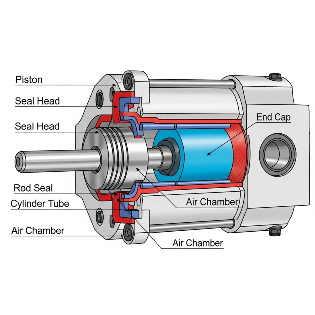
How Do the Internal Components Work Together?
Understanding how internal components interact reveals why proper maintenance and quality components are essential for reliable operation.
Internal cylinder components work together as an integrated system where the cylinder body contains pressure, the piston converts pressure to force, seals maintain pressure boundaries, and the rod transmits force to external loads.
Cylinder Body Function
The cylinder body serves as the pressure vessel containing the working fluid and guiding piston movement. Most bodies use seamless steel tubing or aluminum extrusions for optimal strength-to-weight ratio.
Internal surface finish critically affects performance – honed bores with 0.4-0.8 Ra surface finish ensure smooth seal operation2 and extended component life.
Wall thickness must withstand operating pressure with appropriate safety factors. Standard industrial cylinders handle 10-16 bar with 4:1 safety margins built into the design.
Body materials include carbon steel for general use, stainless steel for corrosive environments, and aluminum alloys for weight-sensitive applications.
Piston Assembly Operation
The piston acts as the movable pressure boundary that converts fluid pressure into linear force. Piston design significantly affects cylinder performance, efficiency, and service life.
Piston materials typically use aluminum for lightweight, fast-acting applications or steel for heavy-duty, high-force operations. Material selection affects acceleration characteristics and force capacity.
Piston seals create the critical pressure boundary between cylinder chambers. Primary seals handle pressure containment while secondary seals prevent leakage and contamination.
Piston diameter directly determines force output according to F = P × A. Larger pistons generate more force but require greater fluid volume and flow capacity.
Seal System Integration
Seals work as an integrated system where each type serves specific functions. Primary piston seals maintain pressure separation, rod seals prevent external leakage, and wipers remove contamination.
Seal materials must match operating conditions – NBR for general use, polyurethane for wear resistance, PTFE for chemical compatibility, and Viton for high temperatures.
Seal installation requires precise techniques and proper lubrication. Incorrect installation causes immediate failure and poor performance that affects the entire system.
Seal performance directly impacts cylinder efficiency, with worn seals reducing force output and causing erratic operation that affects production quality.
Rod and End Cap Assembly
The piston rod transmits cylinder force to external loads while maintaining pressure seal integrity. Rod design must handle applied forces without buckling or excessive deflection.
Rod materials include chrome-plated steel for corrosion resistance, stainless steel for harsh environments, and specialized alloys for extreme conditions.
End caps seal the cylinder ends and provide mounting points. They must withstand full system pressure plus external mounting loads without failure or leakage.
Mounting configurations include clevis, trunnion, flange, and foot mounting styles. Proper mounting selection prevents stress concentration and premature component failure.
| Component | Material Options | Key Function | Failure Impact |
|---|---|---|---|
| Cylinder Body | Steel, Aluminum, SS | Pressure containment | Complete system failure |
| Piston | Aluminum, Steel | Force conversion | Reduced performance |
| Seals | NBR, PU, PTFE, Viton | Pressure isolation | Leakage, contamination |
| Rod | Chrome Steel, SS | Force transmission | Load handling failure |
| End Caps | Steel, Aluminum | System closure | Pressure loss |
What Role Does Pressure Play in Cylinder Operation?
Pressure serves as the fundamental energy source that enables cylinder operation and determines performance characteristics.
Pressure plays the central role in cylinder operation by providing the driving force for motion, determining maximum force output, affecting operating speed, and influencing system efficiency and reliability.
Pressure as Energy Source
Compressed air or hydraulic fluid under pressure contains stored energy that converts to mechanical work when released. Higher pressures store more energy per unit volume.
Pressure energy density varies dramatically between pneumatic and hydraulic systems. Hydraulic systems operate at 100-300 bar while pneumatic systems typically use 6-10 bar.
Energy release rate depends on flow capacity and pressure differential. Rapid pressure changes enable fast cylinder operation while controlled release provides smooth motion.
System pressure must remain stable for consistent performance. Pressure fluctuations cause erratic motion and reduced force output that affects production quality.
Force Output Relationship
Force output directly correlates with operating pressure according to F = P × A. Doubling pressure doubles available force, making pressure control critical for performance.
Effective pressure equals supply pressure minus losses through valves, fittings, and flow restrictions. System design must minimize these losses for optimal performance.
Pressure differential across the piston determines net force. Back pressure on the exhaust side reduces effective pressure and available force output.
Maximum theoretical force occurs at maximum system pressure with atmospheric exhaust pressure, creating the largest possible pressure differential.
Speed Control Through Pressure
Cylinder speed depends on flow rate, which relates to pressure differential across flow restrictions. Higher pressure differentials increase flow rates and cylinder speed.
Flow control valves use pressure drops to regulate speed. Meter-in control restricts supply flow while meter-out control restricts exhaust flow for different characteristics.
Pressure regulation maintains consistent speeds despite load variations. Without regulation, speed varies with changing loads and supply pressure fluctuations.
Quick exhaust valves bypass flow restrictions to accelerate motion by allowing rapid pressure release directly to atmosphere.
System Pressure Management
Pressure regulators maintain consistent operating pressure despite supply variations. This ensures repeatable performance and protects components from overpressure.
Pressure relief valves provide safety protection by limiting maximum system pressure. They prevent damage from pressure spikes or system malfunctions.
Accumulator systems store pressurized fluid to handle peak demands and smooth pressure fluctuations. They improve system response and efficiency.
Pressure monitoring enables predictive maintenance by detecting leaks, blockages, and component degradation before they cause failures.
How Do Different Cylinder Types Work?
Various cylinder designs operate on the same basic principles but with different configurations optimized for specific applications and performance requirements.
Different cylinder types work using the same pressure differential principle but with variations in actuation method, mounting style, and internal configuration to optimize performance for specific applications and operating conditions.
Single-Acting Cylinder Operation
Single-acting cylinders apply pressure to only one side of the piston, using springs or gravity for return motion. This simple design reduces air consumption and control complexity.
Spring return cylinders use internal compression springs to retract the piston when pressure releases. Spring force must overcome friction and external loads for reliable return.
Gravity return designs rely on weight or external forces for retraction. This suits vertical applications where gravity assists return motion without requiring springs.
Force output is limited by spring force during extension. The spring reduces net available force for external work, requiring larger cylinders for equivalent output.
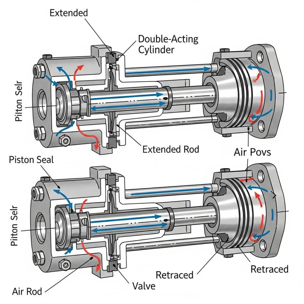
Double-Acting Cylinder Operation
Double-acting cylinders apply pressure to both sides alternately, providing powered motion in both directions with independent speed and force control.
Extend and retract forces differ due to rod area reducing effective piston area on one side. Extend force is typically 15-20% higher than retract force.
Independent flow control enables different speeds for each direction, optimizing cycle times for varying load conditions and application requirements.
Position holding capability is excellent since pressure maintains position against external forces in both directions without energy consumption.
Telescopic Cylinder Function
Telescopic cylinders achieve long strokes in compact packages using multiple nested stages that extend sequentially. Each stage extends fully before the next begins.
Pressure routing systems ensure proper sequence operation through internal passages or external manifolds that control flow to each stage.
Force output decreases with each extending stage as effective area reduces. First stage provides maximum force while final stages provide minimum force.
Retraction occurs in reverse order with the last extended stage retracting first. This maintains structural integrity and prevents binding.
Rotary Cylinder Operation
Rotary cylinders convert linear piston motion into rotational output through internal rack-and-pinion or vane mechanisms for applications requiring rotary motion.
Rack-and-pinion designs use linear piston motion to drive a gear rack that rotates a pinion shaft. Rotation angle depends on stroke length and gear ratio.
Vane-type rotary cylinders use pressure acting on vanes to create direct rotational motion without linear-to-rotary conversion mechanisms.
Torque output depends on pressure, effective area, and moment arm. Higher pressures and larger effective areas increase available torque output.
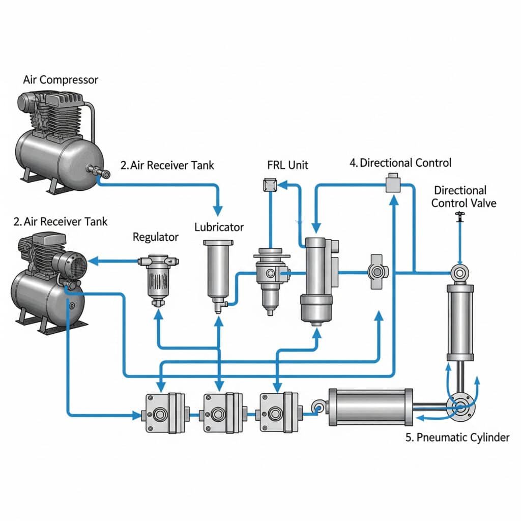
How Do Control Systems Make Cylinders Work?
Control systems orchestrate cylinder operation by managing air flow, pressure, and timing to achieve desired motion profiles and system coordination.
Control systems make cylinders work by using directional valves to control fluid flow direction, flow control valves to regulate speed, pressure controls to manage force, and sensors to provide feedback for precise operation.
Directional Control Valve Operation
Directional control valves determine fluid flow paths to extend or retract cylinders. Common configurations include 3/2-way for single-acting and 5/2-way for double-acting cylinders.
Valve actuation methods include manual, pneumatic pilot, solenoid, and mechanical operation. Selection depends on control system requirements and application needs.
Valve response time affects system performance in high-speed applications. Fast-acting valves enable rapid direction changes and precise timing control.
Flow capacity must match cylinder requirements for desired operating speeds. Undersized valves create restrictions that limit performance and efficiency.
Flow Control Integration
Flow control valves regulate fluid flow rates to control cylinder speed and acceleration characteristics. Meter-in control affects acceleration while meter-out influences deceleration.
Bi-directional flow control enables independent speed adjustment for extend and retract motions, optimizing cycle times for different loading conditions.
Pressure-compensated flow controls maintain consistent speeds despite pressure variations, ensuring repeatable performance across different operating conditions.
Electronic flow control uses proportional valves for precise, programmable speed control with variable acceleration and deceleration profiles.
Pressure Control Systems
Pressure regulators maintain consistent operating pressure for repeatable force output and stable performance despite supply pressure variations.
Pressure switches provide simple position feedback based on chamber pressures, detecting end-of-stroke conditions and system malfunctions.
Proportional pressure control enables variable force output for applications requiring different force levels during operation or for different products.
Pressure monitoring systems detect leaks, blockages, and component degradation before they cause system failures or safety hazards.
Sensor Integration
Position sensors provide feedback for closed-loop control systems. Options include magnetic reed switches, Hall effect sensors, and linear encoders for different accuracy requirements.
Limit switches detect end-of-stroke positions and provide safety interlocks to prevent overtravel and protect system components from damage.
Pressure sensors monitor system performance and detect developing problems such as leaks, restrictions, or component wear before failures occur.
Temperature sensors protect against overheating in continuous duty applications and provide data for predictive maintenance programs.
System Integration Capabilities
PLC integration enables coordination with other machine functions through standard communication protocols and I/O connections for complex automation systems.
Network connectivity allows remote monitoring and control through industrial networks3 such as Ethernet/IP, Profibus, or DeviceNet for centralized management.
HMI interfaces provide operator control and system monitoring capabilities through touchscreen displays and graphical user interfaces.
Data logging captures performance information for analysis, troubleshooting, and optimization of system operation and maintenance procedures.
What Forces and Calculations Govern Cylinder Operation?
Understanding the forces and calculations involved in cylinder operation enables proper sizing, performance prediction, and system optimization.
Cylinder operation is governed by force calculations (F = P × A), speed equations (V = Q/A), acceleration analysis (F = ma), and efficiency factors that determine sizing requirements and performance characteristics.
Basic Force Calculations
Theoretical force equals pressure times effective piston area: F = P × A. This fundamental equation determines maximum available force under ideal conditions.
Effective area differs between extend and retract in double-acting cylinders: A_extend = π × D²/4, A_retract = π × (D² – d²)/4, where D is piston diameter and d is rod diameter.
Practical force accounts for efficiency losses typically ranging 85-90% of theoretical due to friction, seal drag, and flow restrictions.
Safety factors should be applied to calculated loads, typically 1.5-2.5 depending on application criticality and load uncertainty.
Speed and Flow Relationships
Cylinder speed relates to volumetric flow rate: V = Q/A, where velocity equals flow rate divided by effective piston area.
Flow rate depends on valve capacity, pressure differential, and system restrictions. Flow limitations anywhere in the system reduce maximum achievable speed.
Acceleration time depends on net force and moving mass: t = (V × m)/F_net, where higher net forces enable faster acceleration to desired speeds.
Deceleration characteristics depend on exhaust flow capacity and back pressure. Cushioning systems control deceleration to prevent shock loads.
Load Analysis Requirements
Static loads include component weight, process forces, and friction. All static forces must be overcome before motion begins.
Dynamic loads add acceleration forces during motion: F_dynamic = F_static + (m × a), where acceleration forces can exceed static loads significantly.
Side loads and moments must be considered for proper guide system sizing. Cylinders have limited side load capacity without external guides.
Combined loading analysis ensures all force components are within cylinder and system capabilities for reliable operation.
Air Consumption Calculations
Air consumption per cycle equals cylinder volume times pressure ratio: V_air = V_cylinder × (P_absolute/P_atmospheric).
Double-acting cylinders consume air for both strokes while single-acting cylinders only consume air for the powered stroke direction.
System losses through valves, fittings, and leakage typically add 20-30% to theoretical consumption values.
Compressor sizing must handle peak demand plus losses with adequate reserve capacity to prevent pressure drops during operation.
Performance Optimization
Bore size selection balances force requirements with speed and air consumption. Larger bores provide more force but use more air and may move slower.
Stroke length affects air consumption and response time. Longer strokes require more air volume and longer fill times for motion initiation.
Operating pressure optimization considers force needs, energy costs, and component life. Higher pressures reduce cylinder size but increase energy consumption.
System efficiency improves with proper component sizing, minimal pressure drops, and effective air treatment that reduces losses and maintenance.
| Parameter | Calculation | Units | Typical Values |
|---|---|---|---|
| Force | F = P × A | Newtons | 500-50,000N |
| Speed | V = Q/A | m/s | 0.1-10 m/s |
| Air Consumption | V = stroke × area × pressure ratio | liters/cycle | 1-50 L/cycle |
| Power | P = F × V | Watts | 100-10,000W |
How Do Environmental Factors Affect Cylinder Operation?
Environmental conditions significantly impact cylinder performance, reliability, and service life through various mechanisms that must be considered in system design.
Environmental factors affect cylinder operation through temperature changes that alter fluid properties and seal performance, contamination that causes wear and malfunction, humidity that creates corrosion, and vibration that accelerates component fatigue.
Temperature Impact on Operation
Operating temperature affects fluid viscosity, density, and pressure. Higher temperatures reduce air density and effective force output in pneumatic systems.
Seal materials have temperature limits affecting performance and life. Standard NBR seals operate -20°C to +80°C while specialized materials extend temperature ranges.
Thermal expansion of components can affect clearances and seal performance. Design must accommodate thermal growth to prevent binding or excessive wear.
Condensation occurs when compressed air cools below dew point temperature. Water accumulation causes corrosion, freezing, and erratic operation.
Contamination Effects
Dust and debris cause seal wear, valve sticking, and internal component damage. Contamination is the leading cause of premature cylinder failure.
Particle size affects damage severity – particles larger than seal clearances cause immediate damage while smaller particles cause gradual wear.
Chemical contamination attacks seals and causes corrosion. Material compatibility is critical in environments with chemicals, solvents, or process fluids.
Moisture contamination causes corrosion of internal components and can freeze in cold conditions, blocking air passages and preventing operation.
Humidity and Corrosion
High humidity increases condensation risk in compressed air systems. Water vapor condenses as air cools, creating liquid water in the system.
Corrosion affects steel components and can cause pitting, scaling, and eventual failure. Stainless steel or protective coatings prevent corrosion damage.
Galvanic corrosion occurs when dissimilar metals contact in the presence of moisture. Proper material selection prevents galvanic corrosion problems.
Drainage systems must remove accumulated water from system low points. Automatic drains prevent water buildup that causes operational problems.
Vibration and Shock Effects
Mechanical vibration causes fastener loosening, seal displacement, and component fatigue. Proper mounting and isolation protect against vibration damage.
Shock loads from rapid direction changes or external impacts can damage internal components. Cushioning systems reduce shock loads and extend life.
Resonance amplifies vibration effects when operating frequencies match component natural frequencies. Design should avoid resonant conditions.
Foundation stability affects system performance. Rigid mounting prevents excessive vibration while flexible mounting provides isolation.
Altitude and Pressure Effects
High altitude reduces atmospheric pressure, affecting pneumatic cylinder performance. Force output decreases as atmospheric back pressure reduces.
Pressure differential calculations must account for altitude effects. Sea level calculations don’t apply directly at high altitude installations.
Air density decreases with altitude, reducing mass flow rates and affecting cylinder speed characteristics at constant volumetric flow.
Compressor performance also decreases with altitude, requiring larger compressors or higher operating pressures to maintain system performance.
What Common Problems Prevent Proper Cylinder Operation?
Understanding common problems and their root causes enables effective troubleshooting and preventive maintenance strategies.
Common cylinder problems include seal leakage causing force loss, contamination causing erratic motion, improper sizing leading to poor performance, and inadequate air treatment4 resulting in premature component failure.
Seal-Related Problems
Internal leakage between chambers reduces force output and causes sluggish operation. Worn piston seals are the most common cause of performance degradation.
External leakage around the rod creates safety hazards and wastes compressed air. Rod seal failure typically results from contamination or surface damage.
Seal extrusion occurs when seals are forced into clearance gaps under high pressure. This damages seals and creates permanent leakage paths.
Seal hardening from heat or chemical exposure reduces flexibility and sealing effectiveness. Proper material selection prevents chemical compatibility problems.
Contamination Issues
Particle contamination accelerates seal wear and causes valve malfunction. Inadequate filtration is the primary cause of contamination problems.
Water contamination causes corrosion and can freeze in cold conditions. Proper air drying prevents water-related problems and extends component life.
Oil contamination from compressors causes seal swelling and degradation. Oil-free compressors or effective oil removal prevents contamination.
Chemical contamination attacks seals and metal components. Material compatibility analysis prevents chemical damage in harsh environments.
Sizing and Application Problems
Undersized cylinders cannot provide adequate force for the application, resulting in slow operation or inability to complete the work cycle.
Oversized cylinders waste energy and may operate too quickly for proper control. Proper sizing optimizes performance and energy efficiency.
Inadequate guide systems allow side loading that causes binding and premature wear. External guides may be required for side load applications.
Improper mounting creates stress concentrations and misalignment that accelerate component wear and reduce system reliability.
System Design Issues
Inadequate flow capacity limits cylinder speed and creates pressure drops that reduce force output and system efficiency.
Poor valve selection affects response time and flow characteristics. Valve capacity must match cylinder requirements for optimal performance.
Insufficient air treatment allows contamination and moisture to damage components. Proper filtration and drying are essential for reliability.
Inadequate pressure regulation causes erratic performance and may damage components through overpressure conditions.
Maintenance-Related Problems
Infrequent filter changes allow contamination buildup that damages components and reduces system reliability and performance.
Improper lubrication causes increased friction and accelerated wear. Both under-lubrication and over-lubrication create problems.
Delayed seal replacement allows minor leaks to become major failures that require extensive repairs and cause extended downtime.
Lack of performance monitoring prevents early detection of developing problems that could be corrected before causing failures.
| Problem Category | Symptoms | Root Causes | Prevention Methods |
|---|---|---|---|
| Seal Failure | Leakage, reduced force | Contamination, wear | Clean air, proper materials |
| Contamination | Erratic motion, sticking | Poor filtration | Adequate air treatment |
| Sizing Issues | Poor performance | Incorrect selection | Proper calculations |
| System Problems | Inconsistent operation | Design deficiencies | Professional design |
| Maintenance | Premature failure | Neglect | Scheduled maintenance |
How Do Modern Cylinders Integrate with Automation Systems?
Modern cylinders incorporate advanced technologies and communication capabilities that enable seamless integration with sophisticated automation systems.
Modern cylinders integrate with automation systems through embedded sensors for position feedback, electronic controls for precise operation, communication protocols for network connectivity, and diagnostic capabilities for predictive maintenance.
Sensor Integration Technologies
Embedded position sensors eliminate external sensing requirements while providing accurate position feedback for closed-loop control systems.
Magnetic sensors detect piston position through cylinder walls using Hall effect or magnetoresistive technologies that provide analog position signals.
Optical encoders mounted on external carriages provide the highest resolution position feedback for precision positioning applications.
Pressure sensors monitor chamber pressures for force feedback and diagnostic information that enables advanced control strategies and condition monitoring.
Electronic Control Integration
Servo valves provide proportional flow control based on electrical command signals, enabling precise velocity and position control with programmable profiles.
Electronic pressure control uses proportional pressure valves to provide variable force output and pressure regulation for consistent performance.
Integrated controllers combine valve control, sensor processing, and communication functions in compact packages that simplify system integration.
Fieldbus connectivity enables distributed control architectures where individual cylinders communicate directly with central control systems.
Communication Protocol Support
Industrial Ethernet protocols including EtherNet/IP, Profinet, and EtherCAT enable high-speed communication and real-time control coordination.
Fieldbus protocols such as DeviceNet, Profibus, and CANopen provide robust communication for distributed control applications.
Wireless communication options enable monitoring and control of mobile or remote cylinders without physical cable connections.
OPC-UA support provides standardized communication for Industry 4.0 applications and integration with enterprise systems.
Diagnostic and Monitoring Capabilities
Built-in diagnostics monitor performance parameters and component condition to enable predictive maintenance and prevent unexpected failures.
Vibration monitoring detects developing mechanical problems such as bearing wear, misalignment, or mounting issues before they cause failures.
Temperature monitoring protects against overheating and provides data for thermal analysis and system optimization.
Usage tracking records cycle counts, operating hours, and performance trends for maintenance scheduling and life cycle analysis.
Industry 4.0 Integration
IoT connectivity enables remote monitoring and control through cloud-based platforms that provide global access to system information.
Data analytics capabilities process operational data to identify optimization opportunities and predict maintenance requirements.
Digital twin integration creates virtual models of physical cylinders for simulation, optimization, and predictive analysis.
Machine learning algorithms analyze operational data to optimize performance and predict component failures before they occur.
Safety System Integration
Safety-rated sensors and controls meet functional safety requirements for applications requiring SIL-rated safety5 functions.
Integrated safety functions include safe stop, safe position monitoring, and safe speed monitoring that eliminate external safety devices.
Redundant systems provide backup operation and monitoring for critical safety applications where failure could cause injury or damage.
Safety communication protocols ensure reliable transmission of safety-critical information between system components.
Conclusion
Cylinders work through the elegant application of Pascal’s Law, converting fluid pressure into precise linear motion through coordinated operation of internal components, control systems, and environmental protection features that enable reliable automation across countless industrial applications.
FAQs About How Cylinders Work
How does a pneumatic cylinder work?
A pneumatic cylinder works by using compressed air pressure acting on a piston surface to create linear force according to F = P × A, with directional valves controlling air flow to extend or retract the piston and attached rod.
What is the basic principle behind cylinder operation?
The basic principle is Pascal’s Law, where pressure applied to confined fluid transmits equally in all directions, creating force when pressure differential acts across a movable piston surface within the cylinder.
How do single-acting and double-acting cylinders work differently?
Single-acting cylinders use air pressure for one direction with spring or gravity return, while double-acting cylinders use air pressure for both extend and retract motions, providing powered movement in both directions.
What role do seals play in cylinder operation?
Seals maintain pressure boundaries between cylinder chambers, prevent external leakage around the rod, and block contamination entry, enabling proper pressure differential and force generation for reliable operation.
How do you calculate cylinder force output?
Calculate cylinder force using F = P × A, where force equals air pressure times effective piston area, accounting for rod area reduction on the retract stroke and efficiency losses of 10-15%.
What causes cylinders to work improperly?
Common causes include seal leakage reducing force output, contamination causing erratic motion, improper sizing for the application, inadequate air treatment, and poor maintenance allowing component degradation.
How do modern cylinders integrate with automation systems?
Modern cylinders integrate through embedded sensors for position feedback, electronic controls for precise operation, communication protocols for network connectivity, and diagnostic capabilities for predictive maintenance and Industry 4.0 applications.
What environmental factors affect how cylinders work?
Environmental factors include temperature affecting fluid properties and seal performance, contamination causing wear and malfunction, humidity creating corrosion, vibration accelerating fatigue, and altitude affecting pressure differentials and performance.
Footnotes
-
Learn more about Pascal’s Law and its fundamental role in fluid mechanics. ↩
-
Discover the different types of seals used in industrial cylinders and their applications. ↩
-
Explore various Industrial Ethernet protocols used for high-speed communication in automation systems. ↩
-
Understand international standards for compressed air quality and their importance in pneumatic systems. ↩
-
Understand Safety Integrity Levels (SIL) in functional safety and their relevance to industrial automation. ↩
