Are you struggling with high energy costs in your pneumatic systems? Many industrial operations face this challenge daily. The solution lies in understanding and optimizing energy conversion efficiency across your pneumatic components.
L'efficacité de la conversion énergétique dans les systèmes pneumatiques fait référence à l'efficacité avec laquelle l'énergie d'entrée est transformée en travail utile de sortie. En règle générale, les systèmes pneumatiques standard n'atteignent qu'un rendement de 10-30%, le reste étant perdu sous forme de chaleur, de frottement et de pertes de charge.
I’ve spent over 15 years helping companies improve their pneumatic systems, and I’ve seen firsthand how proper efficiency analysis can reduce operational costs by up to 40%. Let me share what I’ve learned about maximizing the performance of components like rodless cylinders.
Table des matières
- How to Calculate Mechanical Efficiency in Pneumatic Systems?
- What Makes Thermal Recovery Systems Effective in Pneumatic Applications?
- How Can You Quantify and Reduce Entropy-Related Losses?
- Conclusion
- FAQs About Energy Efficiency in Pneumatic Systems
How to Calculate Mechanical Efficiency in Pneumatic Systems?
Understanding mechanical efficiency starts with measuring the actual work output against the theoretical energy input. This ratio reveals how much energy your system wastes during operation.
Mechanical efficiency in pneumatic systems equals the useful work output divided by the energy input, typically expressed as a percentage. For rodless cylinders, this calculation must account for friction losses, air leakage, and mechanical resistance in the system.

The Basic Efficiency Formula
The fundamental formula for calculating mechanical efficiency is:
η = (W_out / E_in) × 100%
Où ?
- η (eta) represents efficiency percentage
- W_out is the useful work output (in joules)
- E_in is the energy input (in joules)
Measuring Work Output in Rodless Cylinders
For rodless pneumatic cylinders specifically, we can calculate work output using:
W_out = F × d
Où ?
- F is the force produced (in newtons)
- d is the distance traveled (in meters)
Calculating Energy Input
The energy input for a pneumatic system can be determined by:
E_in = P × V
Où ?
- P is the pressure (in pascals)
- V is the volume of compressed air consumed (in cubic meters)
Real-World Efficiency Factors
I remember working with a manufacturing client in Germany last year who was experiencing efficiency issues. Their rodless cylinder system was operating at only 15% efficiency. After analyzing their setup, we discovered three main issues:
- Excessive friction in the sealing system
- Air leaks at connection points
- Improper sizing of air supply lines
By addressing these issues, we increased their system efficiency to 27%, resulting in annual energy savings of approximately €42,000.
Efficiency Comparison Table
| Component Type | Typical Efficiency Range | Main Loss Factors |
|---|---|---|
| Standard Rodless Cylinder | 15-25% | Seal friction, air leakage |
| Magnetic Rodless Cylinder | 20-30% | Magnetic coupling losses, friction |
| Electric Rodless Actuator1 | 65-85% | Motor losses, mechanical friction |
| Guided Rodless Cylinder | 18-28% | Guide friction, alignment issues |
What Makes Thermal Recovery Systems Effective in Pneumatic Applications?
Thermal recovery systems2 capture and repurpose waste heat generated during pneumatic operations, turning an efficiency problem into an opportunity for energy savings.
Thermal recovery systems in pneumatic applications work by collecting waste heat from compressors and converting it to usable energy for facility heating, water heating, or even power generation. These systems can recover up to 80% of the waste heat energy.

Types of Thermal Recovery Systems
When implementing thermal recovery for pneumatic systems, you have several options:
1. Air-to-Water Heat Exchangers
These systems transfer heat from compressed air to water, which can then be used for:
- Facility heating
- Process water heating
- Preheating boiler feed water
2. Air-to-Air Heat Recovery
This approach uses waste heat to warm incoming air for:
- Space heating
- Process air preheating
- Drying operations
3. Integrated Energy Recovery Systems
Modern integrated systems combine multiple recovery methods for maximum efficiency:
| Recovery Method | Typical Heat Recovery | Best Application |
|---|---|---|
| Water Jacket Recovery | 30-40% | Hot water production |
| Aftercooler Recovery | 20-25% | Process heating |
| Oil Cooler Recovery | 10-15% | Low-grade heating |
| Récupération de l'air d'échappement | 5-10% | Space heating |
Implementation Considerations
When I visited a food processing plant in Wisconsin, they were venting all their compressor heat outdoors. By installing a simple heat recovery system, they now use this energy to preheat their boiler feed water, saving approximately $28,000 annually in natural gas costs.
The key factors to consider when implementing thermal recovery include:
- Temperature differential requirements
- Distance between heat source and potential use
- Consistency of heat production
- Capital investment vs. projected savings
ROI Calculation
To determine if thermal recovery makes financial sense, use this simple formula:
ROI Period (years) = Installation Cost / Annual Energy Savings
Most well-designed thermal recovery systems achieve ROI within 1-3 years.
How Can You Quantify and Reduce Entropy-Related Losses?
Entropy increase represents disorder and unusable energy in your pneumatic system. Quantifying these losses helps identify improvement opportunities that standard efficiency metrics might miss.
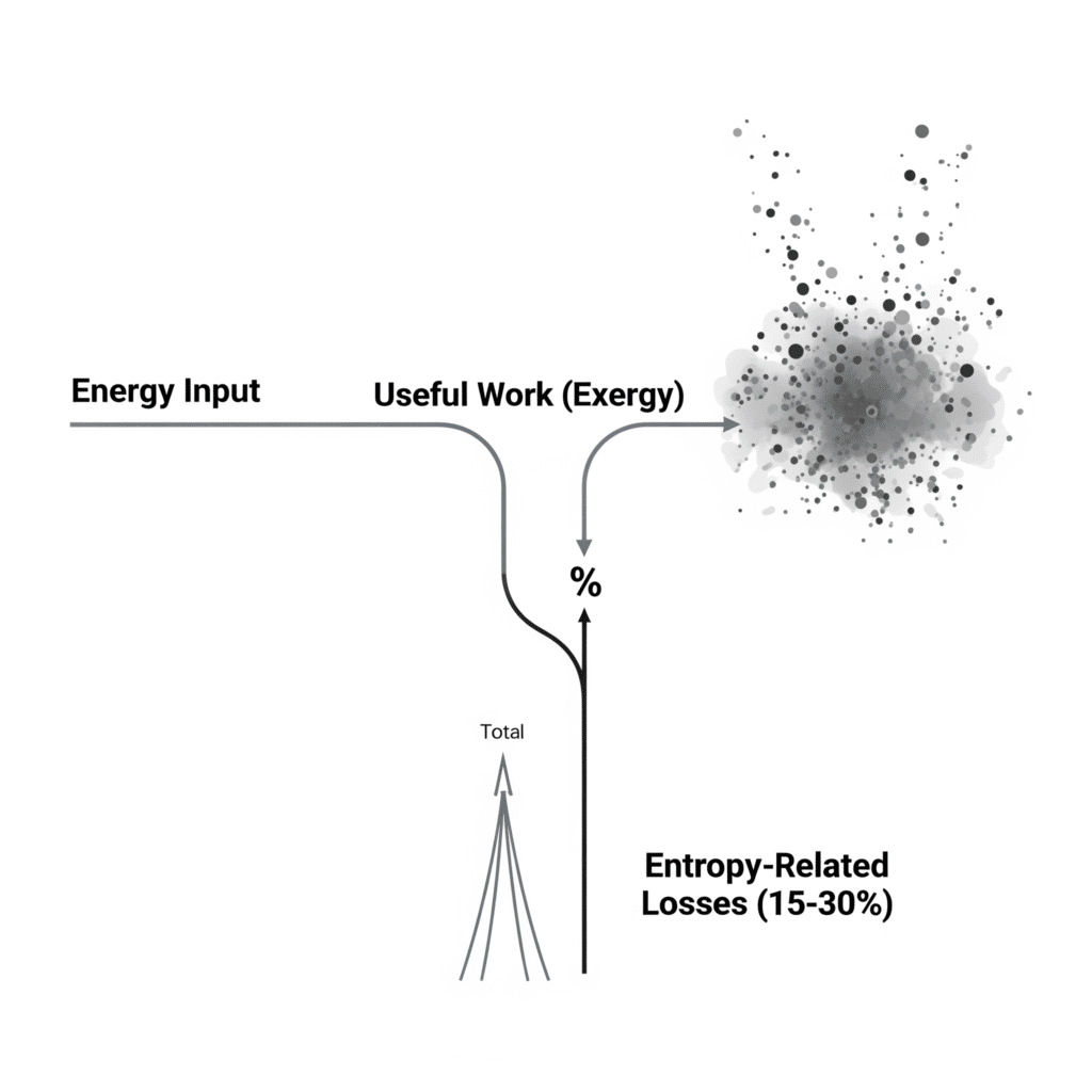
Entropy-related losses in pneumatic systems can be quantified using exergy analysis3, which measures the maximum useful work possible during a process. These losses typically account for 15-30% of total energy input and can be reduced through proper system design and maintenance.

Understanding Entropy in Pneumatic Systems
In pneumatic applications, entropy increases occur during:
- Air compression
- Pressure drops across valves and fittings
- Expansion processes
- Friction in moving components like rodless cylinders
Quantifying Entropy Increase
The mathematical expression for entropy change is:
ΔS = Q/T
Où ?
- ΔS is the change in entropy
- Q is the heat transferred
- T is the absolute temperature
Exergy Analysis Framework
For practical applications, exergy analysis provides a more useful framework:
- Calculate available energy at each system point
- Determine exergy destruction between points
- Identify components with highest exergy losses
Common Sources of Entropy Losses
Based on my experience working with hundreds of pneumatic systems, these are the typical entropy loss sources in order of impact:
1. Pressure Regulation Losses
When pressure is reduced through regulators without performing work, significant exergy is destroyed. This is why proper system pressure selection is critical.
2. Throttling Losses
Flow restrictions in valves, fittings, and undersized lines create pressure drops that increase entropy.
| Composant | Typical Pressure Drop | Entropy Increase |
|---|---|---|
| Standard Elbow | 0.3-0.5 bar | Moyen |
| Ball Valve | 0.1-0.3 bar | Faible |
| Quick Connect | 0.4-0.7 bar | Haut |
| Flow Control Valve | 0.5-2.0 bar | Très élevé |
3. Expansion Losses
When compressed air expands without performing useful work, entropy increases substantially.
Practical Entropy Reduction Strategies
Last year, I worked with a packaging equipment manufacturer in Illinois who was experiencing efficiency issues with their rodless cylinder systems. By applying exergy analysis, we identified that their control valve configuration was creating excessive entropy.
By implementing these changes:
- Relocating valves closer to actuators
- Increasing supply line diameters
- Optimizing control sequences to reduce pressure cycling
They reduced entropy-related losses by 22%, improving overall system efficiency by 8.5%.
Advanced Monitoring Approaches
Modern pneumatic systems can benefit from real-time entropy monitoring:
- Temperature sensors at key points
- Pressure transducers throughout the system
- Flow meters to track consumption
- Computerized analysis to identify entropy trends
Conclusion
Maximizing energy conversion efficiency in pneumatic systems requires a comprehensive approach addressing mechanical efficiency, thermal recovery, and entropy reduction. By implementing these strategies, you can significantly reduce operational costs while improving system performance and reliability.
FAQs About Energy Efficiency in Pneumatic Systems
What is the typical energy efficiency of a pneumatic system?
Most standard pneumatic systems operate at 10-30% efficiency, meaning 70-90% of input energy is lost. Modern, optimized systems can achieve up to 40-45% efficiency through careful design and component selection.
How does a rodless pneumatic cylinder compare to electric alternatives for energy efficiency?
Rodless pneumatic cylinders typically operate at 15-30% efficiency, while electric rodless actuators can achieve 65-85% efficiency. However, pneumatic systems often have lower initial costs and excel in certain applications requiring force density or inherent compliance.
What are the main causes of energy loss in pneumatic systems?
The primary energy losses in pneumatic systems come from air compression (50-60%), transmission losses through piping (10-15%), control valve losses (10-20%), and actuator inefficiencies (15-25%).
How can I identify air leaks in my pneumatic system?
You can identify air leaks through ultrasonic leak detection, pressure decay testing, soap solution application at suspected leak points, or thermal imaging to detect temperature differences caused by escaping air.
What is the payback period for implementing energy efficiency measures in pneumatic systems?
Most energy efficiency improvements in pneumatic systems have payback periods of 6-24 months, depending on system size, operating hours, and local energy costs. Simple measures like leak repair often pay back within 3 months.
How does pressure affect energy consumption in pneumatic systems?
For every 1 bar (14.5 psi) reduction in system pressure, energy consumption typically decreases by 7-10%. Operating at the minimum required pressure is one of the most effective efficiency strategies.
ies.
-
Details the technology behind electric actuators and provides evidence for why their energy efficiency is significantly higher than pneumatic alternatives. ↩
-
Offers in-depth information and case studies on how thermal recovery technology is implemented to capture and reuse waste heat from industrial air compressors. ↩
-
Delves into the thermodynamic principles of exergy analysis, explaining how this method is used to identify and quantify sources of energy inefficiency. ↩


