

High-speed pneumatic cylinder ไม่ใช่แค่กระบอกสูบมาตรฐานที่สั่งให้ valve เปิดเร็วขึ้น การทำงานเร็วทำให้ flow demand, แรงดันตกคร่อม, end-of-stroke energy, heat, seal wear, sensor timing และ guide load เปลี่ยนอย่างมีนัยสำคัญ วิศวกรจึงต้องระบุ motion profile, load, air path, cushioning, mounting และ acceptance test ตั้งแต่ RFQ ไม่ใช่รอปรับ speed controller ตอน commissioning
ในงาน factory automation ปัญหาที่เจอบ่อยคือ catalog piston speed ถูกใช้แทน application proof ทั้งที่ความเร็วจริงขึ้นกับ moving mass, stroke, valve flow, tube ID/length, FRL แรงดันตกคร่อม, exhaust restriction, cushion setting และ pressure ที่วัดได้ที่ cylinder port ขณะเคลื่อนที่ หากไม่ตรวจครบ เครื่องอาจวิ่งเร็วใน bench test แต่ช้าหรือกระแทกเมื่อใส่ load และ cycle rate จริง
ประเด็นสำคัญ
- กำหนด extend time, retract time, dwell, moving mass และ cycle rate ก่อนเลือก bore หรือ valve
- Static pressure บน ตัวควบคุมแรงดัน ไม่พิสูจน์ว่า air path ส่ง flow ได้พอ ต้องวัด dynamic pressure ที่ port
- End energy เพิ่มตามกำลังสองของ speed จึงต้องตรวจ cushion และ shock absorber ทุกครั้งในงาน high-speed
- Acceptance test ต้องรวม timing, pressure, temperature, leakage, sensor state และ end behavior ที่ production load
อะไรทำให้ High-Speed Pneumatic Cylinders แตกต่าง?
งาน high-speed เปลี่ยนความเสี่ยงจาก force calculation ธรรมดาไปสู่ระบบ dynamic ทั้งชุด กระบอกสูบอาจมีแรงพอใน steady state แต่ถ้า valve และ tubing เติมลมไม่ทัน ระหว่าง stroke แรงดันที่ port จะตกและ speed จะไม่ถึงเป้าหมาย ในทางกลับกัน หากเพิ่ม flow มากเกินโดยไม่ตรวจ stop energy กระบอกสูบอาจชน end cover หรือ external stop อย่างรุนแรง
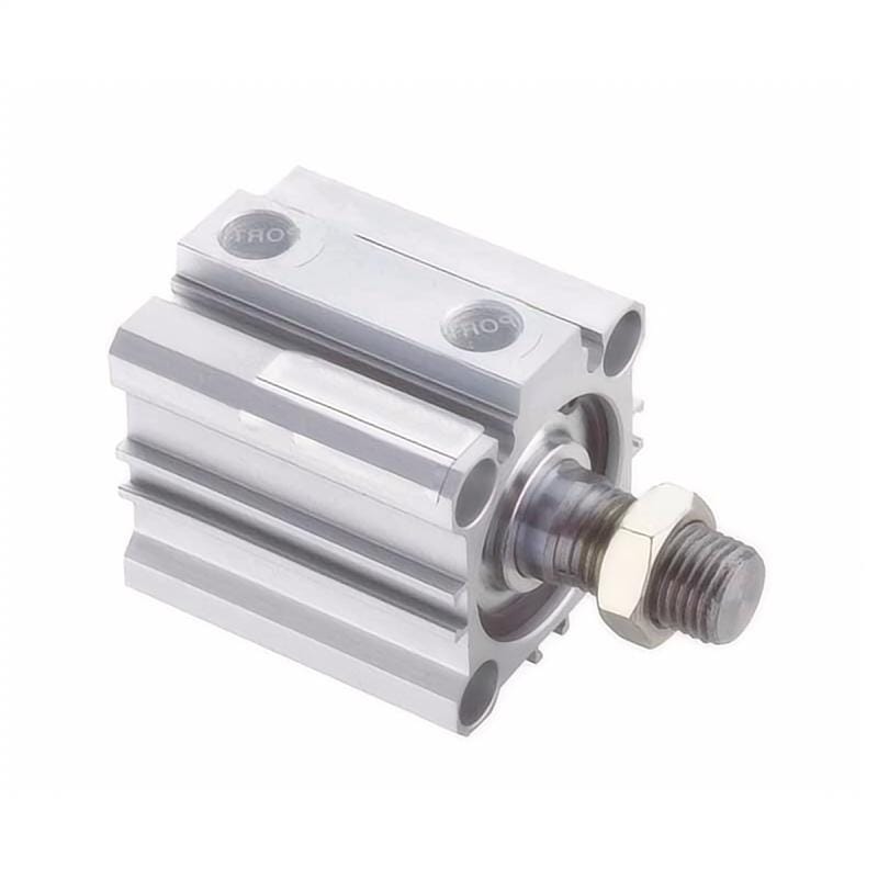
ผู้ผลิตบางรายให้คำเตือนเรื่อง ความเร็วขณะเข้าสู่ช่วงกันกระแทก หรือข้อจำกัดเมื่อความเร็วเกินระดับหนึ่ง เช่นกรอบ 50% ของ Parker ที่ควรทำให้วิศวกรหยุดและตรวจ energy, mass และ cushion chart ใหม่ ไม่ใช่ใช้เป็นตัวเลขอนุมัติอัตโนมัติ เพราะ application แต่ละงานมี moving mass และ stop condition ต่างกัน
Motion และ Load Inputs ใดต้องล็อกก่อน?
ก่อนเลือก cylinder ต้องกำหนด stroke ที่ใช้จริง, extend time, retract time, dwell time, peak cycle rate, burst duration, moving mass, load direction, friction, acceleration, tooling offset และ แรงจากกระบวนการ หากใช้ค่าเฉลี่ยรายวันแทน peak sustained rate จะ under-size valve และทำให้ heat หรือ แรงดันตกคร่อม เกิดเฉพาะช่วงผลิตจริงที่หนักที่สุด
| Required input | Specify this | Do not substitute this |
|---|---|---|
| Stroke | Usable travel และ overtravel | Nominal machine pitch อย่างเดียว |
| Extend time | Command-to-position time under load | Unloaded bench speed |
| Retract time | Separate return requirement | สมมติว่าสองทิศทางเหมือนกัน |
| Dwell | Time at each end position | Average cycle time เท่านั้น |
| Cycle rate | Peak sustained และ short-burst rate | Daily average production |
| Moving mass | Tooling, bracket, product, coupler, carriage | Product weight อย่างเดียว |
สำหรับงาน pick-and-place, reject pusher หรือ clamp ที่ทำงานเร็ว ต้องแยก mass ของ tooling ออกจาก product และต้องรู้ว่า load เปลี่ยนระหว่าง cycle หรือไม่ หาก cylinder ดันผ่าน linkage หรือ guide ให้รวม friction และ side load ด้วย ไม่ควรใช้ force margin สูงเพื่อชดเชยข้อมูล motion ที่ไม่ชัด เพราะอาจทำให้ air consumption และ impact energy สูงเกินจำเป็น
Valve, Tubing และ FRL ส่ง Flow ที่ต้องการได้หรือไม่?
air path ทั้งชุดเป็นตัวกำหนด speed ไม่ใช่ cylinder เพียงตัวเดียว ต้องตรวจ ท่อเมนของโรงงาน, FRL, directional valve, fittings, speed controls, tube ID/length, exhaust muffler และ quick exhaust หากมี จุดคอขวดเล็กเพียงจุดเดียวจะทำให้ dynamic pressure ตก ขณะเดียวกัน valve ที่ใหญ่มากแต่ติดตั้งไกลอาจเพิ่ม dead volume และ response lag
| Air-path input | What the supplier needs |
|---|---|
| Minimum dynamic supply pressure | Pressure measured while the cylinder moves |
| Valve model and flow rating | Cv, ISO flow value หรือ manufacturer flow curve |
| Tube เส้นผ่านศูนย์กลางภายใน and length | แต่ละทิศทาง จาก valve ถึง cylinder |
| Fittings | Quantity, thread size และ restrictive elbows หรือ speed controllers |
| FRL model | Rated flow และ pressure-drop curve ที่ demand ต้องการ |
| Exhaust hardware | Muffler, manifold exhaust หรือ quick-exhaust arrangement |
ตรวจ Cushioning และ Stop Energy อย่างไร?
พลังงานที่ต้องหยุดปลาย stroke ขึ้นกับ moving mass และ speed เป็นกำลังสอง หาก speed เพิ่มสองเท่า energy เพิ่มประมาณสี่เท่า ดังนั้น cylinder ที่ดูใช้ได้ในงานช้าอาจไม่ผ่านเมื่อ cycle time ถูกบีบให้สั้นลง ต้องคำนวณ พลังงานจลน์, drive energy จากแรงดัน, gravity contribution หากมี และเปรียบเทียบกับ cushion หรือ shock absorber limit ของผู้ผลิต
| Stop method | Appropriate use | Required proof |
|---|---|---|
| Elastic bumper | พลังงานต่ำและ repetition ต่ำใน catalog limits | Rated speed, mass และ cycle life |
| Adjustable pneumatic cushion | Load หรือ speed เปลี่ยนใน cushion diagram | Entry speed, mass, setting range, no rebound |
| Self-adjusting pneumatic cushion | Repeated motion ใน mapped range ของผู้ผลิต | Approved mass-speed envelope |
| External hydraulic shock absorber | built-in cushion ไม่พอหรือ stop energy ต้องแม่นยำ | Energy per stroke และ energy per hour |
| External mechanical stop | ตำแหน่งถูกกำหนดนอก cylinder | Stop strength plus separate energy absorber |
Mounting, Guides และ Sensors ใดควรอยู่ใน Specification?
งาน high-speed ขยายผลของ misalignment และ side load ให้รุนแรงขึ้น Rod, bearing, carriage, tooling และ external guide ต้องอยู่ใน load path ที่ถูกต้อง หากใช้ compact cylinder โดยให้ rod รับ side load แทน guide จะเกิด seal wear และ response ไม่เสถียรเร็วขึ้น Sensors ต้องมี response และ placement ที่รองรับ overshoot, bounce และ PLC timeout ไม่ใช่แค่ตรวจว่า detect ได้ใน jog mode
ควรระบุ mounting style, guide type, allowable moment, rod lock หรือ brake หากใช้, sensor type, switch repeatability, cable routing และ guard clearance หากต้องหยุดที่ตำแหน่งแม่นยำ ให้กำหนด external stop หรือ shock absorber ที่แยกจาก cylinder cushion เพราะ cushion มีหน้าที่ลด energy ไม่ใช่เป็น precision locating surface เสมอไป
ควร Validate Temperature และ Duty Cycle อย่างไร?
High cycle rate ทำให้ valve coil, seals, exhaust devices และ cylinder body ร้อนขึ้นได้ แม้ load ต่อ stroke จะไม่สูงมาก ต้องตรวจ ambient temperature, compressed-air temperature, cylinder surface/seal area temperature และ duty profile ใน production recipe ที่แย่ที่สุด ไม่ควรใช้การทดสอบไม่กี่รอบตอนเครื่องเย็นเป็นหลักฐานอายุการใช้งาน
| Environmental input | RFQ requirement | Acceptance evidence |
|---|---|---|
| Ambient temperature | Minimum และ maximum รอบ actuator | Logged during production test |
| Compressed-air temperature | Maximum at point of use | Measured during peak demand |
| Cylinder temperature | Allowed surface หรือ seal-area limit | Stabilized trend ไม่ใช่ spot reading เดียว |
| Duty profile | Sustained rate และ burst duration | Timed run at worst production recipe |
| Air quality | Filtration, dew point และ lubrication policy | FRL setup และ maintenance record |
| Contamination | Dust, coolant, washdown, chemicals | Material และ sealing compatibility review |
หากต้องใช้ cylinder ในพื้นที่ร้อน เย็น ฝุ่น coolant หรือ washdown ให้ตรวจ seal compound, grease, wiper, rod coating, switch rating และ connector protection พร้อมกัน การเพิ่ม speed โดยไม่ตรวจ environment มักทำให้ failure ถูกเข้าใจผิดว่าเป็นปัญหา supplier ทั้งที่เกิดจาก duty หรือ air quality ไม่ตรงสเปก
High-Speed Pneumatic Cylinder RFQ Checklist
RFQ ควรส่งข้อมูลที่ทำให้ supplier คำนวณและรับผิดชอบ boundary ได้จริง หากส่งเพียง bore, stroke และ required speed ผู้ขายอาจเลือกจาก catalog speed โดยไม่รู้ moving mass, tubing, valve, guide และ stop energy ที่ต้องรับในเครื่องจริง
Application and motion
ระบุ stroke, extend/retract time, dwell, รอบต่อนาที, burst duration, required position confirmation, PLC timeout และสัญญาณ end-of-stroke ที่ต้องใช้ production acceptance อย่าลืมระบุว่าต้องการ speed สูงในทิศทางเดียวหรือทั้งสองทิศทาง
Load and mechanics
ระบุ moving mass ทั้งหมด, load direction, guide arrangement, friction, acceleration, tooling offset, side load, stop method และ แรงจากกระบวนการ หากมี linkage ให้ส่ง drawing ที่แสดงมุมและตำแหน่ง load center เพื่อให้ตรวจ force และ moment ได้จริง
Air supply and control
ระบุ plant pressure, minimum dynamic pressure, valve model หรือ flow requirement, tube ID/length, FRL, fittings, muffler, quick exhaust, speed controller และ air quality ที่ point of use หากผู้ขายต้องเลือก valve ให้ขอ flow calculation และ pressure-drop assumption กลับมา
Environment and life
ระบุ ambient temperature, contamination, washdown, chemicals, cycle count ต่อวัน, expected life, maintenance access และ lubrication policy ข้อมูลนี้มีผลต่อ seal, wiper, rod, bearing และ sensor มากกว่าที่เห็นจาก bore size
Supplier evidence
ขอ catalog limits, cushion/energy check, flow calculation, recommended valve/tube, guide/mounting notes, temperature limits, spare parts, lead time และ acceptance test criteria จาก supplier เพื่อให้ purchasing เปรียบเทียบ scope ได้ ไม่ใช่เปรียบเทียบราคา cylinder เปล่า
Commissioning and Acceptance Test Plan
เริ่ม commissioning ด้วย low-pressure หรือ low-speed cycle เพื่อตรวจการชน, binding และ sensor state จากนั้นเพิ่ม load และ speed ไปยัง production condition พร้อมบันทึก port pressure, cycle time, end behavior, temperature และ leakage ควรทดสอบจำนวนรอบที่พอให้ temperature trend stabilizes ไม่ใช่ทดสอบเพียง 5-10 รอบ
| Acceptance item | Pass criterion to define before test |
|---|---|
| Extend and retract time | Maximum time plus permitted variation |
| Dynamic pressure | Minimum pressure at each cylinder port during motion |
| End-of-stroke behavior | No hard impact, unacceptable bounce, or false sensor transition |
| Temperature | Within exact cylinder, valve, seal, and sensor limits with stable trend |
| Air leakage | No audible or measured leak above the agreed threshold |
| Position confirmation | Correct state within the PLC timeout on every tested cycle |
Acceptance record ควรอยู่กับ machine file พร้อม ตัวควบคุมแรงดัน setting, valve part number, tube length, cushion setting, sensor location, load condition และ production recipe หากหลังจากนั้นต้องเปลี่ยน muffler, speed controller หรือ tube routing ควรทดสอบซ้ำเพราะ air path เปลี่ยนแล้ว
คำถามที่พบบ่อยเกี่ยวกับ High-Speed Pneumatic Cylinder Specification
ความเร็วสูงสุดของ pneumatic cylinder คือเท่าไร?
ไม่มีตัวเลขเดียวที่ใช้ได้ทุก application ความเร็วสูงสุดขึ้นกับรุ่น bore stroke load valve flow tube pressure cushion guide และ stop energy Catalog speed เป็นจุดเริ่มต้น แต่ต้องอนุมัติด้วย calculation และ production-speed test
ควร size cylinder จาก force หรือ speed ก่อน?
ต้องล็อกทั้ง force และ speed ร่วมกัน เริ่มจาก load และ motion profile แล้วเลือก bore ที่ให้ force margin ที่ dynamic pressure จริง จากนั้นตรวจว่า valve, tubing และ FRL ให้ flow พอสำหรับ stroke time ที่ต้องการ
catalog piston speed เพียงพอสำหรับอนุมัติ high-speed application หรือไม่?
ไม่เพียงพอ เพราะ catalog speed ไม่รวม load, air path, mounting, cushion energy, sensor timing และ duty cycle ของเครื่องจริง ต้องมี acceptance test ที่ production load และ speed พร้อม dynamic pressure measurement
เมื่อใดควรใช้ external shock absorber?
เมื่อ internal cushion หรือ bumper ไม่สามารถรับ energy per stroke, energy per hour หรือ repeatability ที่ต้องการได้ หรือเมื่อ stop position ต้องแม่นยำและไม่ควรใช้ cushion เป็นตัวกำหนดตำแหน่งสุดท้าย
หลังติดตั้งควร verify high-speed cylinder อย่างไร?
วัด extend/retract time, dynamic port pressure, end impact, bounce, sensor state, temperature trend และ leakage ที่ production load และ cycle rate จริง เก็บข้อมูลก่อน-หลังการปรับ cushion หรือ flow control เพื่อให้ maintenance มี baseline
Conclusion
High-speed pneumatic cylinder ที่เชื่อถือได้เกิดจากการออกแบบระบบ ไม่ใช่การเลือก cylinder เร็วเพียงตัวเดียว ให้เริ่มจาก motion และ load ที่นิยามชัด ตรวจ air path แบบ dynamic คำนวณ stopping energy เลือก mounting และ sensors ให้เหมาะ แล้วพิสูจน์ด้วย acceptance test ที่เหมือน production จริง แนวทางนี้ช่วยให้ผู้ซื้อและวิศวกรเห็นต้นทุนครบทั้ง actuator, valve, tubing, guide, shock absorber และ downtime ที่อาจเกิดขึ้น
แรงกระบอกสูบที่ต้องการ = แรงจากกระบวนการ + แรงเร่ง + แรงเสียดทาน + องค์ประกอบของแรงโน้มถ่วงท่อเมนของโรงงาน -> ท่อแยก -> วาล์วแยกและวาล์วเริ่มทำงานแบบนุ่มนวล -> ตัวกรอง -> ตัวควบคุมแรงดันพลังงานจลน์ = 0.5 x มวลเคลื่อนที่ทั้งหมด x ความเร็วขณะเข้าสู่ช่วงกันกระแทก^2