Every plant manager I meet faces the same frustration: traditional pneumatic systems are “dumb” power-hungry machines in an increasingly smart manufacturing world. You’re trying to implement Industry 4.01 strategies, but your pneumatic systems remain black boxes – consuming energy, failing unpredictably, and providing zero actionable data. This intelligence gap is costing you thousands in wasted energy and unplanned downtime.
Intelligent pneumatic control systems combine IoT-enabled components using appropriate communication protocols, edge computing2 modules for real-time processing, and digital twin3 modeling to reduce energy consumption by 25-35% while providing predictive maintenance capabilities and process optimization insights.
Last month, I visited a pharmaceutical manufacturing facility in Ireland that transformed their operation by implementing our intelligent control approach. Their validation manager showed me their energy consumption dashboard, revealing a 32% reduction in compressed air usage while simultaneously increasing production throughput by 18%. Let me show you how they achieved these results and how you can replicate their success.
Table of Contents
- IoT Pneumatic Component Protocol Analysis
- Edge Computing Module Performance Comparison
- Digital Twin Modeling Accuracy Requirements
- Conclusion
- FAQs About Intelligent Pneumatic Control
Which Communication Protocol Best Connects Your Pneumatic Components to IoT Systems?
Selecting the wrong communication protocol for pneumatic IoT integration is one of the most expensive mistakes I see companies make. Either the protocol lacks the necessary features for effective control, or it’s overly complex for the application, driving up implementation costs unnecessarily.
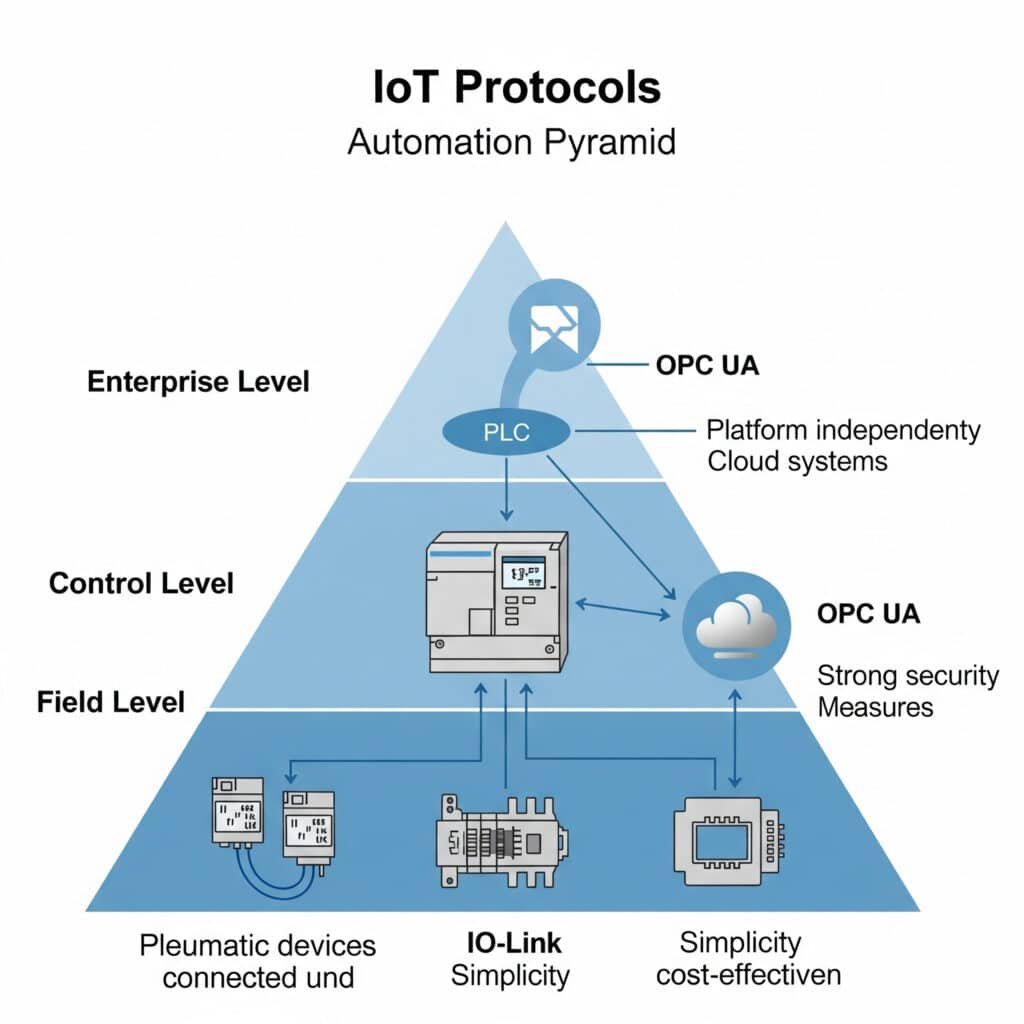
The optimal communication protocol for pneumatic IoT integration depends on your specific requirements for data rate, power consumption, range, and existing infrastructure. For most industrial pneumatic applications, IO-Link4 provides the best balance of simplicity, cost-effectiveness, and functionality, while OPC UA5 offers superior interoperability for enterprise-wide integration.

Protocol Comparison for Pneumatic Applications
After implementing hundreds of intelligent pneumatic systems across various industries, I’ve compiled this comparison of the most relevant protocols:
| Protocol | Data Rate | Range | Power Consumption | Complexity | Best For |
|---|---|---|---|---|---|
| IO-Link | 230 kbps | 20m | Low | Low | Component-level integration |
| MQTT | Variable | Network dependent | Very low | Medium | Data acquisition |
| OPC UA | Variable | Network dependent | Medium | High | Enterprise integration |
| EtherNet/IP | 10/100 Mbps | 100m | High | High | High-speed control |
| PROFINET | 100 Mbps | 100m | High | High | Deterministic control |
Protocol Selection Framework
When helping clients select the right protocol for their pneumatic IoT implementation, I use this decision framework:
Step 1: Define Communication Requirements
Start by determining your specific needs:
- Data Volume: How much data will each component generate?
- Update Frequency: How often do you need new data points?
- Control Requirements: Do you need real-time control or just monitoring?
- Existing Infrastructure: What protocols are already in use?
Step 2: Evaluate Protocol Capabilities
Match your requirements to protocol capabilities:
IO-Link
Perfect for direct component integration when you need:
- Simple point-to-point communication
- Easy parameter setting and diagnostics
- Cost-effective implementation
- Compatibility with higher-level protocols
IO-Link is particularly well-suited for pneumatic valve terminals, pressure sensors, and flow meters where direct, component-level communication is needed.
MQTT
Ideal for data acquisition when you need:
- Lightweight messaging for constrained devices
- Publish/subscribe architecture
- Excellent for cloud connectivity
- Low bandwidth consumption
MQTT works well as a transport layer for pneumatic system monitoring data that needs to reach cloud platforms or dashboards.
OPC UA
Best for enterprise integration when you need:
- Vendor-independent communication
- Complex information modeling
- Integrated security
- Scalability across the organization
OPC UA excels in environments where pneumatic systems need to communicate with multiple systems from different vendors.
Step 3: Implementation Planning
Consider these factors for successful implementation:
- Gateway Requirements: Determine if protocol translation is needed
- Security Considerations: Evaluate encryption and authentication needs
- Scalability: Plan for future expansion
- Maintenance: Consider long-term support and updates
Case Study: Automotive Manufacturing Protocol Selection
I recently worked with an automotive components manufacturer in Michigan who was struggling to integrate their pneumatic systems into their factory monitoring platform. They initially attempted to use EtherNet/IP for everything, which created unnecessary complexity for simple devices.
We implemented a tiered approach:
- IO-Link for direct connection to smart pneumatic valves and sensors
- An IO-Link master with MQTT capability for data transport
- OPC UA at the SCADA level for enterprise integration
This hybrid approach reduced implementation costs by 43% while providing all the functionality they needed. The simplified architecture also reduced maintenance requirements and improved reliability.
Protocol Implementation Tips
For the most successful implementation, follow these guidelines:
Data Optimization
Don’t transmit everything just because you can. For each pneumatic component, identify:
- Critical operating parameters (pressure, flow, temperature)
- Status indicators and diagnostics
- Configuration parameters
- Exception conditions
Transmitting only necessary data reduces network load and simplifies analysis.
Standardization
Develop a standard for how pneumatic components communicate:
- Consistent naming conventions
- Uniform data structures
- Standard diagnostic codes
- Common timestamp formats
This standardization dramatically simplifies integration and analysis.
How Do You Select the Right Edge Computing Module for Pneumatic Control?
Edge computing has revolutionized pneumatic system control by enabling real-time processing and decision-making at the machine level. However, selecting the right edge computing module is critical for success.
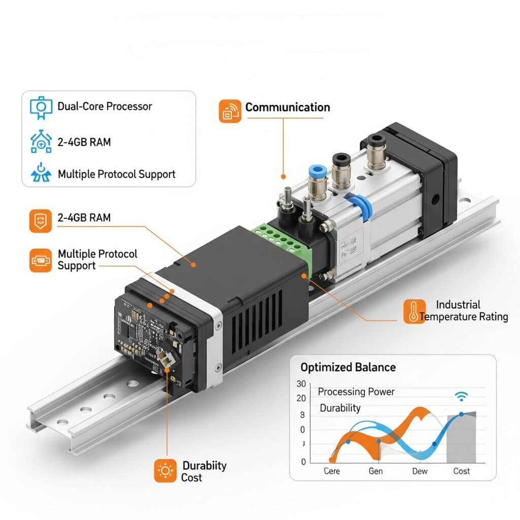
The optimal edge computing solution for pneumatic systems balances processing power, communication capabilities, environmental durability, and cost. For most industrial applications, modules with dual-core processors, 2-4GB RAM, multiple protocol support, and industrial temperature ratings provide the best performance-to-cost ratio.

Edge Computing Module Comparison
This comparison table highlights the key differences between edge computing options for pneumatic control applications:
| Feature | Basic Edge Gateway | Mid-Range Edge Controller | Advanced Edge Computer |
|---|---|---|---|
| Processor | Single-core, 800MHz | Dual-core, 1.2GHz | Quad-core, 1.6GHz+ |
| Memory | 512MB-1GB | 2-4GB | 4-8GB |
| Storage | 4-8GB Flash | 16-32GB SSD | 64GB+ SSD |
| I/O Options | Limited digital I/O | Moderate I/O + fieldbus | Extensive I/O + multiple protocols |
| Protocol Support | 1-2 protocols | 3-5 protocols | 6+ protocols |
| Analytics Capability | Basic data filtering | Pattern recognition | ML/AI capable |
| Typical Cost | $300-600 | $800-1,500 | $1,800-3,500 |
| Best For | Simple monitoring | Control & optimization | Complex analytics |
Performance Requirements by Application
Different pneumatic applications have varying edge computing requirements:
Basic Monitoring Applications
- Processor: Single-core sufficient
- Memory: 512MB adequate
- Key feature: Low power consumption
- Example use: Remote monitoring of pneumatic system status
Control & Efficiency Applications
- Processor: Dual-core recommended
- Memory: 2GB minimum
- Key feature: Deterministic response time
- Example use: Real-time pressure and flow optimization
Predictive Maintenance Applications
- Processor: Dual/Quad-core needed
- Memory: 4GB+ recommended
- Key feature: Local data storage
- Example use: Vibration analysis and failure prediction
Process Optimization Applications
- Processor: Quad-core preferred
- Memory: 8GB recommended
- Key feature: Machine learning capability
- Example use: Adaptive control based on product variations
Selection Criteria Framework
When selecting edge computing modules for pneumatic applications, evaluate these critical factors:
Processing Requirements
Calculate your processing needs based on:
- Number of connected pneumatic components
- Data sampling frequency
- Complexity of control algorithms
- Future expansion plans
For a typical pneumatic system with 20-30 smart components, a dual-core processor with 2-4GB RAM provides sufficient headroom for most applications.
Environmental Considerations
Industrial environments demand robust hardware:
- Temperature rating: Look for -20°C to 70°C operating range
- Ingress protection: IP54 minimum, IP65 preferred
- Vibration resistance: 5G minimum for machine mounting
- Power input range: Wide input range (e.g., 9-36VDC)
Communication Capabilities
Ensure support for required protocols:
- Downward communication: IO-Link, Modbus, fieldbus systems
- Upward communication: OPC UA, MQTT, REST API
- Horizontal communication: Peer-to-peer options
Implementation Considerations
Don’t overlook these practical factors:
- Mounting options (DIN rail, panel mount)
- Power consumption
- Cooling requirements
- Expansion capabilities
Case Study: Food Processing Edge Computing Implementation
A food processing plant in Wisconsin needed to optimize their pneumatic system that controlled packaging operations. Their challenges included:
- Varying product sizes requiring different pneumatic settings
- High energy costs from inefficient pressure settings
- Frequent unplanned downtime from component failures
We implemented a mid-range edge controller with these capabilities:
- Direct connection to smart pneumatic valves and sensors via IO-Link
- Real-time pressure optimization based on product size
- Pattern recognition for early failure detection
- OPC UA connectivity to plant MES system
Results after 6 months:
- 28% reduction in compressed air consumption
- 45% decrease in unplanned downtime
- 12% increase in overall equipment effectiveness (OEE)
- ROI achieved in 4.5 months
Implementation Best Practices
For successful edge computing implementation in pneumatic systems:
Start with Pilot Projects
Begin with a single machine or production line to:
- Validate technical approach
- Demonstrate value
- Identify implementation challenges
- Build internal expertise
Leverage Existing Infrastructure
Where possible, use:
- Existing network infrastructure
- Compatible protocols
- Familiar programming environments
Plan for Scalability
Design your architecture to:
- Add devices incrementally
- Scale processing capacity
- Expand analytics capabilities
- Integrate with additional systems
What Accuracy Level Does Your Digital Twin Need for Effective Pneumatic System Modeling?
Digital twin technology has transformed how we design, optimize, and maintain pneumatic systems. However, many companies waste resources by either under-specifying (creating ineffective models) or over-specifying (creating unnecessarily complex models) their digital twins.
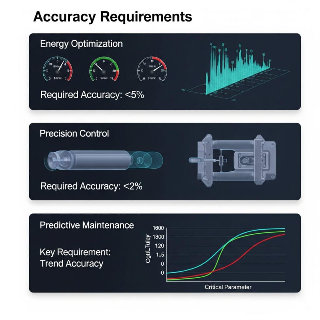
The required accuracy for pneumatic system digital twins varies by application purpose. For energy optimization, ±5% accuracy in flow and pressure modeling is sufficient. For precision control applications, ±2% accuracy is necessary. For predictive maintenance, temporal resolution and trend accuracy are more important than absolute values.

Digital Twin Accuracy Requirements by Application
Different applications require different levels of modeling precision:
| Application | Required Accuracy | Critical Parameters | Update Frequency |
|---|---|---|---|
| Energy Optimization | ±5% | Flow rates, Pressure levels | Minutes to hours |
| Process Control | ±2% | Response times, Position accuracy | Milliseconds to seconds |
| Predictive Maintenance | ±7-10% | Pattern detection, Trend analysis | Hours to days |
| System Design | ±3-5% | Flow capacity, Pressure drops | N/A (static) |
| Operator Training | ±10-15% | System behavior, Response characteristics | Real-time |
Modeling Fidelity Considerations
When developing digital twins for pneumatic systems, these factors determine the required model fidelity:
Physical Parameter Modeling
The accuracy required for different physical parameters varies:
| Parameter | Basic Modeling | Intermediate Modeling | Advanced Modeling |
|---|---|---|---|
| Pressure | Static values | Dynamic response | Transient behavior |
| Flow | Average rates | Dynamic flow | Turbulence effects |
| Temperature | Ambient only | Component heating | Thermal gradients |
| Mechanical | Simple kinematics | Dynamic forces | Friction & compliance |
| Electrical | Binary signals | Analog values | Signal dynamics |
Temporal Resolution
Different applications require different temporal resolution:
- High-frequency dynamics (1-10ms): Required for servo-pneumatic control
- Medium-frequency dynamics (10-100ms): Sufficient for most valve and actuator control
- Low-frequency dynamics (100ms-1s): Adequate for system-level optimization
- Steady-state modeling (>1s): Suitable for energy and capacity planning
Model Complexity Tradeoffs
There’s always a tradeoff between model accuracy and computational requirements:
| Model Complexity | Accuracy | Computation Requirement | Development Time | Best For |
|---|---|---|---|---|
| Simplified | ±10-15% | Very low | Days | Quick assessments, training |
| Standard | ±5-10% | Moderate | Weeks | System optimization, basic control |
| Detailed | ±2-5% | High | Months | Precision control, detailed analysis |
| High-fidelity | <±2% | Very high | Months to years | Research, critical applications |
Digital Twin Development Methodology
For pneumatic system digital twins, I recommend this phased approach:
Phase 1: Define Purpose and Requirements
Start by clearly defining:
- Primary use cases for the digital twin
- Required accuracy for each parameter
- Update frequency needs
- Integration requirements with other systems
Phase 2: Component-Level Modeling
Develop accurate models for individual components:
- Valves (flow coefficients, response times)
- Actuators (force characteristics, dynamic response)
- Tubing (pressure drops, capacitance effects)
- Sensors (accuracy, response time)
Phase 3: System Integration
Combine component models into a system model:
- Component interactions
- System dynamics
- Control algorithms
- Environmental factors
Phase 4: Validation and Calibration
Compare model predictions with actual system performance:
- Steady-state validation
- Dynamic response validation
- Edge case testing
- Sensitivity analysis
Case Study: Manufacturing Digital Twin Implementation
A precision manufacturing company in Germany needed to optimize their pneumatic system that powered assembly operations. They initially planned to create a highly detailed model of their entire system, which would have required months of development time.
After consulting with them, we recommended a tiered approach:
- High-fidelity modeling (±2% accuracy) for critical precision assembly stations
- Standard modeling (±5% accuracy) for general production equipment
- Simplified modeling (±10% accuracy) for support systems
This approach reduced development time by 65% while still providing the accuracy needed for each subsystem. The resulting digital twin enabled:
- Energy consumption reduction of 23%
- Cycle time improvement of 8%
- Predictive maintenance implementation that reduced downtime by 34%
Model Accuracy Validation Methods
To ensure your digital twin meets accuracy requirements:
Static Validation
Compare model predictions with measured values under steady-state conditions:
- Pressure at various points in the system
- Flow rates under different loads
- Force output at different pressures
- Energy consumption at various production rates
Dynamic Validation
Evaluate model performance during transient conditions:
- Step response characteristics
- Frequency response
- Response to disturbances
- Behavior during fault conditions
Long-term Validation
Assess model drift over time:
- Comparison with historical data
- Sensitivity to component aging
- Adaptability to system modifications
Practical Implementation Tips
For successful digital twin implementation:
Start with Critical Subsystems
Don’t try to model everything at once. Begin with:
- Highest energy consumption areas
- Most frequent failure points
- Performance bottlenecks
- Precision-critical applications
Use Appropriate Modeling Tools
Select tools based on your requirements:
- CFD software for detailed flow analysis
- Multi-physics platforms for system-level modeling
- Control system simulation for dynamic response
- Statistical tools for predictive maintenance models
Plan for Model Evolution
Digital twins should grow with your system:
- Start with basic models and increase fidelity as needed
- Update models when physical systems change
- Incorporate new measurement data over time
- Add functionality incrementally
Conclusion
Implementing intelligent control for pneumatic systems requires careful selection of IoT communication protocols, appropriate edge computing modules, and right-sized digital twin modeling. By taking a strategic approach to each of these elements, you can achieve significant energy savings, improved performance, and enhanced reliability from your pneumatic systems.
FAQs About Intelligent Pneumatic Control
What is the typical ROI timeframe for implementing intelligent pneumatic controls?
The typical ROI timeframe for intelligent pneumatic control systems ranges from 6-18 months. Energy savings usually provide the fastest return (often visible within 3-6 months), while predictive maintenance benefits typically show financial returns within 12-18 months as unplanned downtime events are prevented.
How much data storage is required for pneumatic system monitoring?
For a typical pneumatic system with 50 monitoring points sampling at 1-second intervals, approximately 200MB of data storage is required per month for raw values. With edge processing that stores only significant changes and aggregated values, this can be reduced to 20-40MB per month while maintaining analytical value.
Can existing pneumatic systems be retrofitted with intelligent controls?
Yes, most existing pneumatic systems can be retrofitted with intelligent controls without replacing major components. Retrofit options include adding smart sensors to existing cylinders, installing flow meters on main lines, upgrading valve terminals with communication capabilities, and implementing edge computing gateways to collect and process data.
What cybersecurity measures are required for IoT-enabled pneumatic systems?
IoT-enabled pneumatic systems require a defense-in-depth approach to cybersecurity, including network segmentation (isolating OT networks from IT networks), encrypted communications (particularly for wireless protocols), access control for all connected devices, regular firmware updates, and monitoring systems to detect unusual behavior or unauthorized access attempts.
How does intelligent control affect pneumatic system maintenance requirements?
Intelligent control typically reduces overall maintenance requirements by 30-50% by enabling condition-based maintenance rather than time-based maintenance. However, it does introduce new maintenance considerations, including sensor calibration, software updates, and IT/OT integration support that traditional pneumatic systems don’t require.
What level of staff training is needed to implement and maintain intelligent pneumatic controls?
Successful implementation requires cross-training staff in both pneumatic systems and digital technologies. Typically, maintenance technicians need 20-40 hours of training on new diagnostic tools and procedures, while engineering staff require 40-80 hours of training on system configuration, data analysis, and troubleshooting the integrated systems.
-
Provides an overview of Industry 4.0, which represents the fourth industrial revolution characterized by the increasing automation of traditional manufacturing and industrial practices using modern smart technology like IoT, cloud computing, and AI. ↩
-
Offers an explanation of edge computing, a distributed computing paradigm that brings computation and data storage closer to the sources of data (i.e., at the “edge” of the network), reducing latency and bandwidth use for industrial processes. ↩
-
Explains the concept of a digital twin, which is a virtual model of a physical object or system that serves as its digital counterpart, updated with real-time data to simulate, predict, and optimize performance. ↩
-
Describes IO-Link, a standardized, point-to-point, serial communication protocol (IEC 61131-9) used for connecting smart sensors and actuators to a control system, enabling advanced diagnostics and parameterization. ↩
-
Details the principles of OPC UA (Open Platform Communications Unified Architecture), a machine-to-machine communication protocol for industrial automation developed for secure, reliable, and platform-independent data exchange. ↩


