

Production lines stop unexpectedly. Engineers scramble to fix mysterious pneumatic failures. Most people never understand the simple physics that power modern automation.
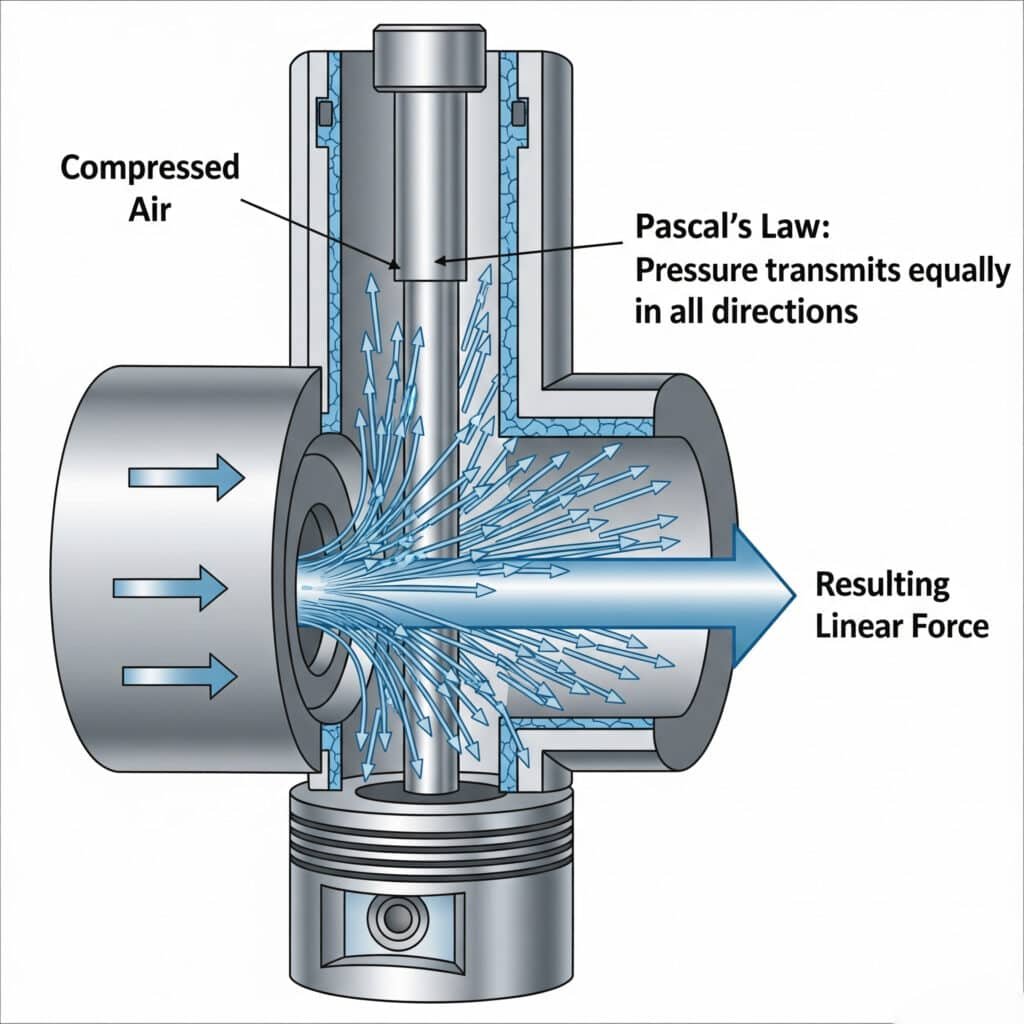
The principle of pneumatic cylinder operation relies on Pascal’s Law, where compressed air pressure acts equally in all directions within a sealed chamber, creating linear force when pressure differential moves a piston through the cylinder bore.
Last year, I visited Sarah, a maintenance supervisor at a Texas automotive plant. Her team was replacing pneumatic cylinders every few weeks without understanding why they failed. I spent two hours explaining the basic principles, and her failure rate dropped by 80% within a month. Understanding the fundamentals changed everything.
Table of Contents
- What Is Pascal’s Law and How Does It Apply to Pneumatic Cylinders?
- How Does Air Pressure Create Linear Motion?
- What Are the Essential Components That Make Pneumatic Cylinders Work?
- How Do Single-Acting vs Double-Acting Cylinders Differ?
- What Role Do Seals and Valves Play in Cylinder Operation?
- How Do You Calculate Force, Speed, and Air Consumption?
- What Are the Advantages and Limitations of Pneumatic Power?
- How Do Environmental Factors Affect Pneumatic Cylinder Performance?
- What Common Problems Occur and How to Prevent Them?
- Conclusion
- FAQs About Pneumatic Cylinder Principles
What Is Pascal’s Law and How Does It Apply to Pneumatic Cylinders?
Pascal’s Law forms the foundation of all pneumatic cylinder operation and explains why compressed air can generate tremendous force.
Pascal’s Law states that pressure applied to a confined fluid transmits equally in all directions, allowing pneumatic cylinders to convert air pressure into linear force by applying pressure differential across a piston surface.
Understanding Pressure Transmission
Pascal’s Law, discovered by Blaise Pascal1 in 1653, explains how confined fluids behave under pressure. When you apply pressure to any point in a confined fluid, that pressure transmits equally throughout the entire fluid volume.
In pneumatic cylinders, compressed air acts as the working fluid. When air pressure enters one side of the cylinder, it pushes against the piston with equal force across the entire piston surface area.
The pressure remains constant throughout the air volume, but the force depends on the surface area where pressure acts. This relationship enables pneumatic cylinders to generate substantial forces from relatively low air pressures.
Mathematical Foundation
The basic force equation follows directly from Pascal’s Law: F = P × A, where force equals pressure times area. This simple relationship governs all pneumatic cylinder calculations.
Pressure units typically use bar, PSI, or Pascal depending on your location. One bar equals approximately 14.5 PSI or 100,000 Pascal.
Area calculations use the effective piston diameter, accounting for rod area in double-acting cylinders. The rod reduces effective area on one side of the piston.
Pressure Differential Concept
Pneumatic cylinders work by creating pressure differences across the piston. Higher pressure on one side creates net force that moves the piston toward the lower pressure side.
Atmospheric pressure (1 bar or 14.7 PSI) exists on the exhaust side unless back pressure is present. The pressure differential determines the actual force output.
Maximum theoretical force occurs when one side has full system pressure and the other side vents to atmosphere. Real systems have losses that reduce actual force output.
Practical Applications
Understanding Pascal’s Law helps troubleshoot pneumatic problems. If pressure drops occur, force output decreases proportionally throughout the system.
System design must account for pressure losses through valves, fittings, and tubing. These losses reduce the effective pressure available at the cylinder.
Multiple cylinders connected to the same pressure source share the available pressure equally, following Pascal’s Law principles.
| Pressure (bar) | Piston Area (cm²) | Theoretical Force (N) | Practical Force (N) |
|---|---|---|---|
| 6 | 50 | 3000 | 2700 |
| 6 | 100 | 6000 | 5400 |
| 8 | 50 | 4000 | 3600 |
| 8 | 100 | 8000 | 7200 |
How Does Air Pressure Create Linear Motion?
The conversion of air pressure into linear motion involves several physical principles working together to create controlled movement.
Air pressure creates linear motion by applying force to a piston surface, overcoming static friction and load resistance, then accelerating the piston and rod assembly through the cylinder bore at speeds determined by air flow rate.
Force Generation Process
Compressed air enters the cylinder chamber and expands to fill the available volume. The air molecules exert pressure against all surfaces, including the piston face.
The pressure force acts perpendicular to the piston surface, creating a net force in the direction of motion. This force must overcome static friction before movement begins.
Once motion starts, kinetic friction replaces static friction, typically reducing the resistance force. The net force then accelerates the piston and attached load.
Motion Control Mechanisms
Air flow rate into the cylinder determines piston velocity. Higher flow rates enable faster motion, while restricted flow creates slower, more controlled movement.
Flow control valves regulate the air flow rate to achieve desired speeds. Meter-in control affects acceleration, while meter-out control influences deceleration and load handling.
Back pressure on the exhaust side provides cushioning and smooth deceleration. Adjustable cushioning valves optimize motion characteristics for specific applications.
Acceleration and Deceleration
Newton’s second law2 (F = ma) governs piston acceleration. Net force divided by moving mass determines acceleration rate.
Initial acceleration is highest when pressure differential is maximum and velocity is zero. As speed increases, flow limitations may reduce acceleration.
Deceleration occurs when exhaust flow becomes restricted or back pressure increases. Controlled deceleration prevents shock loads and improves system life.
Energy Transfer Efficiency
Pneumatic systems typically achieve 25-35% energy efficiency from compressor input to useful work output. Most energy converts to heat during compression and expansion.
Cylinder efficiency depends on friction losses, leakage, and flow restrictions. Well-designed systems achieve 85-95% cylinder efficiency.
System optimization focuses on minimizing pressure drops and using appropriate cylinder sizing to maximize efficiency within practical constraints.
What Are the Essential Components That Make Pneumatic Cylinders Work?
Understanding each component’s function helps you select, maintain, and troubleshoot pneumatic cylinder systems effectively.
Essential pneumatic cylinder components include the cylinder body, piston assembly, piston rod, end caps, seals, ports, and mounting hardware, each designed to work together for reliable linear motion generation.
Cylinder Body Construction
The cylinder body contains the working pressure and guides the piston motion. Most cylinders use seamless steel tubing or aluminum extrusions for the body material.
Internal surface finish critically affects seal life and performance. Honed bores3 with 0.4-0.8 Ra surface finish provide optimal seal operation and long service life.
Wall thickness must withstand operating pressure with appropriate safety factors. Standard designs handle 10-16 bar working pressure with 4:1 safety factors.
Body materials include carbon steel, stainless steel, and aluminum alloys. Material selection depends on operating environment, pressure requirements, and cost considerations.
Piston Assembly Design
The piston separates the cylinder chambers and transmits force to the piston rod. Piston design affects performance, efficiency, and service life.
Piston materials typically use aluminum or steel construction. Aluminum pistons reduce moving mass for faster acceleration, while steel pistons handle higher forces.
Piston seals create the pressure boundary between chambers. Primary seals handle pressure containment, while secondary seals prevent leakage.
Piston diameter determines force output according to F = P × A. Larger pistons generate more force but require more air volume and flow capacity.
Piston Rod Specifications
The piston rod transmits cylinder force to the external load. Rod design must handle applied forces without buckling or deflection.
Rod materials include chrome-plated steel, stainless steel, and specialized alloys. Chrome plating provides corrosion resistance and smooth surface finish.
Rod diameter affects buckling strength and system stiffness. Larger rods handle higher side loads but increase cylinder size and cost.
Rod surface finish impacts seal performance and service life. Smooth, hard surfaces minimize seal wear and extend maintenance intervals.
End Cap and Mounting Systems
End caps seal the cylinder ends and provide mounting points for the cylinder body. They must withstand full system pressure and mounting loads.
Tie rod construction4 uses threaded rods to secure end caps to the cylinder body. This design enables field service and seal replacement.
Welded construction permanently attaches end caps to the cylinder body. This creates a more compact design but prevents field service.
Mounting styles include clevis, trunnion, flange, and foot mounting options. Proper mounting selection prevents stress concentration and premature failure.
| Component | Material Options | Key Function | Failure Modes |
|---|---|---|---|
| Cylinder Body | Steel, Aluminum | Pressure containment | Corrosion, wear |
| Piston | Aluminum, Steel | Force transmission | Seal failure, wear |
| Piston Rod | Chrome steel, SS | Load connection | Buckling, corrosion |
| End Caps | Steel, Aluminum | Pressure sealing | Cracking, leakage |
| Seals | NBR, PU, PTFE | Pressure isolation | Wear, chemical attack |
Seal Technology
Primary piston seals maintain pressure separation between cylinder chambers. Seal selection depends on pressure, temperature, and chemical compatibility requirements.
Rod seals prevent external leakage and contamination entry. They must handle dynamic motion while maintaining effective sealing.
Wiper seals remove contamination from the rod surface during retraction. This protects internal seals and extends service life.
Static seals prevent leakage at threaded connections and end cap interfaces. They handle pressure without relative motion between surfaces.
How Do Single-Acting vs Double-Acting Cylinders Differ?
The choice between single-acting and double-acting cylinders affects performance, control, and application suitability significantly.
Single-acting cylinders use air pressure for motion in one direction with spring or gravity return, while double-acting cylinders use air pressure for motion in both directions, providing better control and higher forces.
Single-Acting Cylinder Operation
Single-acting cylinders apply air pressure to only one side of the piston. The return stroke relies on an internal spring, external spring, or gravity to retract the piston.
Spring return cylinders use internal compression springs to retract the piston when air pressure releases. Spring force must overcome friction and any external loads.
Gravity return cylinders rely on weight or external forces to retract the piston. This design suits vertical applications where gravity assists return motion.
Air consumption is lower since pressurized air is only used for one direction of motion. This reduces compressor requirements and operating costs.
Double-Acting Cylinder Operation
Double-acting cylinders apply air pressure to both sides of the piston alternately. This provides powered motion in both extend and retract directions.
Force output can differ between extend and retract strokes due to rod area reducing effective piston area on one side. Extend force is typically higher.
Speed control is independent for both directions using separate flow control valves. This enables optimized cycle times for different loading conditions.
Position holding capability is excellent since air pressure maintains position against external forces in both directions.
Performance Comparison
Force output in single-acting cylinders is limited by spring force during extension. The spring force reduces net output force available for work.
Double-acting cylinders provide full pneumatic force in both directions, minus friction losses. This maximizes available force for external loads.
Speed control is more limited in single-acting designs since return speed depends on spring characteristics or gravity rather than controlled air flow.
Energy efficiency may favor single-acting designs for simple applications due to lower air consumption and simpler control systems.
Application Selection Criteria
Single-acting cylinders suit simple applications requiring motion in one direction with light return loads. Examples include clamping, pressing, and lifting operations.
Double-acting cylinders work better for applications requiring controlled motion in both directions or high forces during retraction. Material handling and positioning applications benefit from double-acting designs.
Safety considerations may favor single-acting designs that fail to a safe position when air pressure is lost. Spring return ensures predictable failure mode behavior.
Cost analysis should include cylinder price, valve complexity, and air consumption over the system lifetime to determine the most economical choice.
| Feature | Single-Acting | Double-Acting | Best Application |
|---|---|---|---|
| Force Control | One direction only | Both directions | SA: Clamping, DA: Positioning |
| Speed Control | Limited return | Full control | SA: Simple, DA: Complex |
| Air Consumption | Lower | Higher | SA: Cost-sensitive, DA: Performance |
| Position Holding | Moderate | Excellent | SA: Gravity loads, DA: Precision |
| Safety Behavior | Predictable return | Depends on valving | SA: Fail-safe, DA: Controlled |
What Role Do Seals and Valves Play in Cylinder Operation?
Seals and valves are critical components that enable proper pneumatic cylinder function, efficiency, and reliability.
Seals maintain pressure separation and prevent contamination while valves control air flow direction, speed, and pressure to achieve desired cylinder motion and positioning.
Seal Functions and Types
Primary piston seals create pressure barriers between cylinder chambers. They must seal effectively while allowing smooth piston motion with minimal friction.
Rod seals prevent pressurized air from escaping around the piston rod. They also prevent external contamination from entering the cylinder.
Wiper seals remove dirt, moisture, and debris from the rod surface during retraction. This protects internal seals and maintains system cleanliness.
Static seals prevent leakage at threaded connections, end caps, and port fittings. They handle pressure without relative motion between sealing surfaces.
Seal Material Selection
Nitrile rubber (NBR) seals handle general industrial applications with good chemical resistance and moderate temperature range (-20°C to +80°C).
Polyurethane (PU) seals provide excellent wear resistance and low friction for high-cycle applications. They work well in temperatures from -35°C to +80°C.
PTFE seals offer superior chemical resistance and low friction but require careful installation. They handle temperatures from -200°C to +200°C.
Viton seals provide exceptional chemical and temperature resistance for harsh environments. They operate reliably from -20°C to +200°C.
Valve Control Functions
Directional control valves determine air flow direction to extend or retract the cylinder. Common types include 3/2-way and 5/2-way configurations.
Flow control valves regulate air flow rate to control cylinder speed. Meter-in control affects acceleration, while meter-out control influences deceleration.
Pressure control valves maintain consistent operating pressure and provide overload protection. They ensure stable force output and prevent system damage.
Quick exhaust valves accelerate cylinder motion by allowing rapid air discharge directly to atmosphere, bypassing flow restrictions in the main valve.
Valve Selection Criteria
Flow capacity must match cylinder requirements for desired operating speeds. Undersized valves create flow restrictions that limit performance.
Response time affects system performance in high-speed applications. Fast-acting valves enable rapid direction changes and precise positioning.
Pressure rating must exceed maximum system pressure with appropriate safety margins. Valve failure can cause dangerous pressure release.
Environmental compatibility includes temperature range, vibration resistance, and protection against contamination ingress.
System Integration
Valve mounting options include manifold mounting for compact installations or individual mounting for distributed control systems.
Electrical connections must match control system requirements. Options include solenoid operation, pilot operation, or manual override capability.
Feedback signals from position sensors enable closed-loop control systems. Valve response must coordinate with sensor signals for stable operation.
Maintenance access affects system serviceability. Valve placement should allow easy inspection, adjustment, and replacement when needed.
How Do You Calculate Force, Speed, and Air Consumption?
Accurate calculations ensure proper pneumatic cylinder sizing and predict system performance for your specific application requirements.
Calculate pneumatic cylinder force using F = P × A, determine speed from V = Q/A, and estimate air consumption using volume and pressure relationships to optimize system design and performance.
Force Calculation Methods
Theoretical force equals air pressure times effective piston area: F = P × A. This represents maximum available force under ideal conditions.
Effective piston area differs between extend and retract strokes in double-acting cylinders due to rod area: A_retract = A_piston – A_rod.
Practical force accounts for friction losses, typically 10-15% of theoretical force. Seal friction, guide friction, and air flow losses reduce available force.
Load analysis must include static weight, process forces, acceleration forces, and safety factors. Total required force determines minimum cylinder size.
Speed Calculation Principles
Cylinder speed relates directly to air flow rate: V = Q/A, where velocity equals volumetric flow rate divided by effective piston area.
Flow rate depends on valve capacity, pressure differential, and tubing size. Flow restrictions anywhere in the system limit maximum speed.
Acceleration phase speed increases gradually as air flow builds up. Steady-state speed occurs when flow rate stabilizes at maximum capacity.
Deceleration depends on exhaust flow capacity and back pressure. Cushioning systems control deceleration to prevent shock loads.
Air Consumption Analysis
Air consumption per cycle equals cylinder volume times pressure ratio: V_air = V_cylinder × (P_absolute/P_atmospheric).
Double-acting cylinders consume air for both extend and retract strokes. Single-acting cylinders only consume air for the powered stroke.
System losses through valves, fittings, and leakage typically add 20-30% to theoretical consumption. Proper system design minimizes these losses.
Compressor sizing must handle peak demand plus system losses with adequate reserve capacity. Undersized compressors cause pressure drops and poor performance.
Performance Optimization
Bore size selection balances force requirements with speed and air consumption. Larger bores provide more force but use more air and move slower.
Stroke length affects air consumption and system response time. Longer strokes require more air volume and longer fill times.
Operating pressure optimization considers force needs, energy costs, and component life. Higher pressures reduce cylinder size but increase energy consumption and component stress.
System efficiency improves with proper component sizing, minimal pressure drops, and effective air treatment. Well-designed systems achieve 85-95% efficiency.
| Cylinder Bore | Operating Pressure | Extend Force | Retract Force | Air per Cycle |
|---|---|---|---|---|
| 50mm | 6 bar | 1180N | 950N | 2.4 liters |
| 63mm | 6 bar | 1870N | 1500N | 3.7 liters |
| 80mm | 6 bar | 3020N | 2420N | 6.0 liters |
| 100mm | 6 bar | 4710N | 3770N | 9.4 liters |
Practical Calculation Examples
Example 1: 63mm bore cylinder at 6 bar pressure
- Extend force: F = 6 × π × (63/2)² = 1870N
- Air consumption: V = π × (63/2)² × stroke × 6 = stroke × 18.7 liters/meter
Example 2: Required cylinder size for 2000N force at 6 bar
- Required area: A = F/P = 2000/6 = 333 cm²
- Required diameter: D = √(4A/π) = √(4×333/π) = 65mm
These calculations provide starting points for cylinder selection, with final sizing considering safety factors and application-specific requirements.
What Are the Advantages and Limitations of Pneumatic Power?
Understanding pneumatic system benefits and constraints helps determine when pneumatic cylinders are the best choice for your application.
Pneumatic power offers clean operation, simple control, high speed, and safety advantages, but has limitations in force output, energy efficiency, and precise positioning compared to hydraulic and electric alternatives.
Key Advantages of Pneumatic Systems
Clean operation makes pneumatic systems ideal for food processing, pharmaceutical, and clean room applications. Compressed air leakage is harmless to products and environment.
Simple control systems use basic valves and switches for operation. This reduces complexity, training requirements, and maintenance compared to more sophisticated alternatives.
High-speed operation enables rapid cycle times due to low moving mass and compressible air properties. Pneumatic cylinders can achieve speeds up to 10 m/s.
Safety benefits include non-flammable working medium and predictable failure modes. Air leaks don’t create fire hazards or environmental contamination.
Cost effectiveness for simple applications includes low initial cost, simple installation, and readily available compressed air in most industrial facilities.
System Limitations
Force output is limited by practical air pressure levels, typically 6-10 bar in industrial systems. This restricts pneumatic cylinders to moderate force applications.
Energy efficiency is poor, typically 25-35% from compressor input to useful work output. Most energy converts to heat during compression and expansion cycles.
Precise positioning is difficult due to air compressibility and temperature effects. Pneumatic systems struggle with applications requiring positioning accuracy better than ±1mm.
Temperature sensitivity affects performance as air density and pressure change with temperature. System performance varies with ambient conditions.
Noise levels can be significant due to air exhaust and compressor operation. Sound dampening may be required in noise-sensitive environments.
Comparison with Alternative Technologies
Hydraulic systems provide higher forces and better positioning accuracy but require complex fluid handling and create environmental concerns with oil leaks.
Electric actuators offer precise positioning and high efficiency but have higher initial costs and limited speed in high-force applications.
Pneumatic systems excel in applications requiring moderate forces, high speeds, clean operation, and simple control with reasonable initial costs.
Application Suitability Matrix
Ideal applications include packaging, assembly, material handling, and simple automation where speed and cleanliness are more important than precision or high forces.
Poor applications include heavy lifting, precision positioning, continuous duty, and applications where energy efficiency is critical for operating costs.
Hybrid systems sometimes combine pneumatic speed with electric precision or hydraulic force to optimize overall system performance.
| Factor | Pneumatic | Hydraulic | Electric | Best Choice |
|---|---|---|---|---|
| Force Output | Moderate | Very High | High | Hydraulic: Heavy loads |
| Speed | Very High | Moderate | Variable | Pneumatic: Fast cycles |
| Precision | Poor | Good | Excellent | Electric: Positioning |
| Cleanliness | Excellent | Poor | Good | Pneumatic: Clean rooms |
| Energy Efficiency | Poor | Moderate | Excellent | Electric: Continuous duty |
| Initial Cost | Low | High | Moderate | Pneumatic: Simple systems |
Economic Considerations
Operating costs include compressed air generation, maintenance, and energy consumption. Air costs typically range $0.02-0.05 per cubic meter.
Maintenance costs are generally low due to simple construction and readily available replacement parts. Seal replacement is the primary maintenance requirement.
System lifecycle costs should consider initial investment, operating expenses, and productivity benefits over the expected service life.
Return on investment analysis helps justify pneumatic system selection based on improved productivity, reduced labor, and enhanced product quality.
How Do Environmental Factors Affect Pneumatic Cylinder Performance?
Environmental conditions significantly impact pneumatic cylinder operation, reliability, and service life in real-world applications.
Environmental factors including temperature, humidity, contamination, vibration, and corrosive substances affect pneumatic cylinder performance through seal degradation, corrosion, friction changes, and component wear.
Temperature Effects
Operating temperature affects air density, pressure, and component materials. Higher temperatures reduce air density and effective force output.
Seal materials have temperature limits that affect performance and service life. Standard NBR seals work from -20°C to +80°C, while specialized materials extend this range.
Thermal expansion of cylinder components can affect clearances and seal performance. Design must accommodate thermal growth to prevent binding or leakage.
Condensation occurs when compressed air cools below its dew point. Water in the system causes corrosion, freezing, and erratic operation.
Humidity and Moisture Control
High humidity increases condensation risk in compressed air systems. Water accumulation causes component corrosion and erratic operation.
Air treatment systems including filters, dryers, and separators remove moisture and contaminants. Proper air treatment is essential for reliable operation.
Drain systems must remove accumulated condensate from low points in the air distribution system. Automatic drains prevent water buildup.
Dew point5 control maintains air moisture content below levels that cause condensation at operating temperatures. Target dew points are typically 10°C below minimum operating temperature.
Contamination Impact
Dust and debris cause seal wear, valve malfunction, and internal component damage. Filtration systems protect pneumatic components from contamination.
Chemical contamination can attack seals, cause corrosion, and create deposits that interfere with operation. Material compatibility is critical in chemical environments.
Particulate contamination accelerates wear and can cause valve sticking or seal failure. Filter maintenance is essential for system reliability.
Oil contamination from compressors can cause seal swelling and degradation. Oil-free compressors or proper oil removal systems prevent contamination.
Vibration and Shock
Mechanical vibration can cause fastener loosening, seal displacement, and component fatigue. Proper mounting and vibration isolation protect system components.
Shock loads from rapid direction changes or external impacts can damage internal components. Cushioning systems reduce shock loads and extend component life.
Resonance frequencies can amplify vibration effects. System design should avoid operating at resonant frequencies of mounted components.
Foundation stability affects system performance and life. Rigid mounting prevents excessive vibration and maintains proper alignment.
Corrosive Environment Protection
Corrosive atmospheres attack metal components and cause premature failure. Material selection and protective coatings extend service life in harsh environments.
Stainless steel construction provides corrosion resistance but increases system cost. Cost-benefit analysis determines when stainless steel is justified.
Protective coatings including anodizing, plating, and painting provide corrosion protection for standard materials. Coating selection depends on specific environmental conditions.
Sealed designs prevent corrosive substances from contacting internal components. Environmental sealing is critical in harsh applications.
| Environmental Factor | Effect on Performance | Protection Methods | Typical Solutions |
|---|---|---|---|
| High Temperature | Reduced force, seal degradation | Heat shields, cooling | High-temp seals, insulation |
| Low Temperature | Condensation, seal stiffening | Heating, insulation | Cold-weather seals, heaters |
| High Humidity | Corrosion, water buildup | Air drying, drainage | Refrigerated dryers, auto drains |
| Contamination | Wear, malfunction | Filtration, sealing | Filters, wipers, covers |
| Vibration | Loosening, fatigue | Isolation, damping | Shock mounts, cushioning |
| Corrosion | Component degradation | Material selection | Stainless steel, coatings |
What Common Problems Occur and How to Prevent Them?
Understanding common pneumatic cylinder problems and their prevention helps maintain reliable operation and minimize downtime.
Common pneumatic cylinder problems include seal leakage, erratic motion, reduced force output, and premature wear, preventable through proper air treatment, regular maintenance, correct sizing, and environmental protection.
Seal Leakage Issues
Internal leakage between cylinder chambers reduces force output and causes erratic motion. Worn or damaged piston seals are the typical cause.
External leakage around the rod creates safety hazards and air waste. Rod seal failure or surface damage allows pressurized air to escape.
Seal failure causes include contamination, improper installation, chemical incompatibility, and normal wear. Prevention focuses on addressing root causes.
Replacement procedures require proper seal selection, surface preparation, and installation techniques. Incorrect installation causes immediate failure.
Erratic Motion Problems
Stick-slip motion results from friction variations, contamination, or inadequate lubrication. Smooth operation requires consistent friction levels.
Speed variations indicate flow restrictions, pressure fluctuations, or internal leakage. System diagnosis identifies the specific cause.
Position drift occurs when cylinders cannot maintain position against external loads. Internal leakage or valve problems cause position drift.
Hunting or oscillation results from control system instability or excessive gain settings. Proper tuning eliminates unstable operation.
Force Output Reduction
Pressure drops through valves, fittings, and tubing reduce available force at the cylinder. Proper sizing prevents excessive pressure losses.
Internal leakage reduces effective pressure differential across the piston. Seal replacement restores proper force output.
Friction increases due to contamination, wear, or inadequate lubrication. Regular maintenance maintains low friction operation.
Temperature effects reduce air density and available force. System design must account for temperature variations.
Premature Component Wear
Contamination accelerates wear of seals, guides, and internal surfaces. Proper filtration and air treatment prevent contamination damage.
Overloading exceeds design limits and causes rapid wear or failure. Proper sizing with adequate safety factors prevents overload damage.
Misalignment creates uneven loading and accelerated wear. Proper installation and mounting prevent alignment problems.
Inadequate lubrication increases friction and wear. Proper lubrication systems maintain component life.
Preventive Maintenance Strategies
Regular inspection identifies problems before failure occurs. Visual checks, performance monitoring, and leak detection enable proactive maintenance.
Air treatment maintenance includes filter changes, dryer service, and drain system operation. Clean, dry air is essential for reliable operation.
Lubrication schedules maintain proper lubrication levels without over-lubrication that can cause problems. Follow manufacturer recommendations.
Performance monitoring tracks force output, speed, and air consumption to identify degrading performance before failure.
| Problem Type | Symptoms | Root Causes | Prevention Methods |
|---|---|---|---|
| Seal Leakage | Air loss, reduced force | Wear, contamination | Clean air, proper seals |
| Erratic Motion | Inconsistent speed | Friction, restrictions | Lubrication, flow sizing |
| Force Loss | Weak operation | Pressure drops, leaks | Proper sizing, maintenance |
| Premature Wear | Short service life | Overload, contamination | Correct sizing, filtration |
| Position Drift | Cannot hold position | Internal leakage | Seal maintenance, valves |
Troubleshooting Methodology
Systematic diagnosis starts with symptom identification and progresses through logical testing procedures. Document findings to track problem patterns.
Performance testing measures actual force, speed, and air consumption against specifications. This identifies specific performance degradation.
Component testing isolates problems to specific system elements. Replace or repair only the failed components rather than entire assemblies.
Root cause analysis prevents problem recurrence by addressing underlying causes rather than just symptoms. This reduces long-term maintenance costs.
Conclusion
Pneumatic cylinder principles rely on Pascal’s Law and pressure differential to convert compressed air into reliable linear motion, making them essential for modern automation when properly understood and applied.
FAQs About Pneumatic Cylinder Principles
What is the basic principle of pneumatic cylinder operation?
The basic principle uses Pascal’s Law where compressed air pressure acts equally in all directions, creating linear force when pressure differential moves a piston through the cylinder bore, converting pneumatic energy into mechanical motion.
How do you calculate pneumatic cylinder force output?
Calculate pneumatic cylinder force using F = P × A, where force equals air pressure times effective piston area, accounting for rod area reduction on the retract stroke in double-acting cylinders.
What is the difference between single-acting and double-acting pneumatic cylinders?
Single-acting cylinders use air pressure for one direction with spring or gravity return, while double-acting cylinders use air pressure for both directions, providing better control and higher forces in both directions.
Why do pneumatic cylinders lose force over time?
Pneumatic cylinders lose force due to internal seal leakage, pressure drops in the air system, contamination causing friction increases, and normal component wear that reduces system efficiency.
How does air pressure create linear motion in pneumatic cylinders?
Air pressure creates linear motion by applying force to the piston surface according to Pascal’s Law, overcoming static friction and load resistance, then accelerating the piston assembly through the cylinder bore.
What factors affect pneumatic cylinder performance?
Performance factors include air pressure and quality, temperature effects on air density, contamination levels, seal condition, proper sizing for the application, and environmental conditions like humidity and vibration.
How do seals work in pneumatic cylinders?
Seals maintain pressure separation between cylinder chambers, prevent external leakage around the rod, and block contamination entry, using materials like NBR, polyurethane, or PTFE selected for specific operating conditions.
-
Read a biography of Blaise Pascal and learn about his contributions to physics and mathematics. ↩
-
Review the fundamental principles of Newton’s second law and how it governs force, mass, and acceleration. ↩
-
See a technical explanation of the cylinder honing process and how it creates an ideal surface finish for seal performance. ↩
-
Explore the design principles and advantages of tie-rod construction for industrial pneumatic and hydraulic cylinders. ↩
-
Understand the definition of dew point and its critical role in preventing moisture and corrosion in compressed air systems. ↩
