

Engineers face constant pressure to optimize production lines while dealing with space constraints and contamination issues. Traditional rod cylinders create maintenance nightmares and take up valuable floor space.
A rodless air slide works by using compressed air to move an internal piston that connects to an external carriage through magnetic coupling or mechanical linkage, providing linear motion without an exposed rod while integrating precision guides for smooth operation.
Two weeks ago, I received an urgent call from Henrik, a production manager at a Danish food processing plant. His packaging line kept shutting down because chocolate residue was jamming the exposed cylinder rods. We shipped him our magnetic rodless air slides within 48 hours. After installation, his line ran contamination-free for three months straight, saving him over $50,000 in downtime costs.
Table of Contents
- What Are the Main Components of a Rodless Air Slide?
- How Does the Magnetic Coupling System Work?
- What Makes Rodless Cylinders Different from Traditional Ones?
- How Do You Control Speed and Position?
- What Are the Different Types of Force Transfer Mechanisms?
- How Do You Calculate Performance and Sizing?
- What Are Common Applications for Rodless Air Slides?
- What Maintenance and Troubleshooting Steps Are Required?
- Conclusion
- FAQs About Rodless Air Slides
What Are the Main Components of a Rodless Air Slide?
Understanding each component helps you select the right rodless pneumatic cylinder and maintain it properly for years of reliable service.
A rodless air slide contains an aluminum cylinder body, internal piston with coupling mechanism, external carriage with integrated guides, pneumatic ports, position sensors, and mounting hardware designed to work together seamlessly.
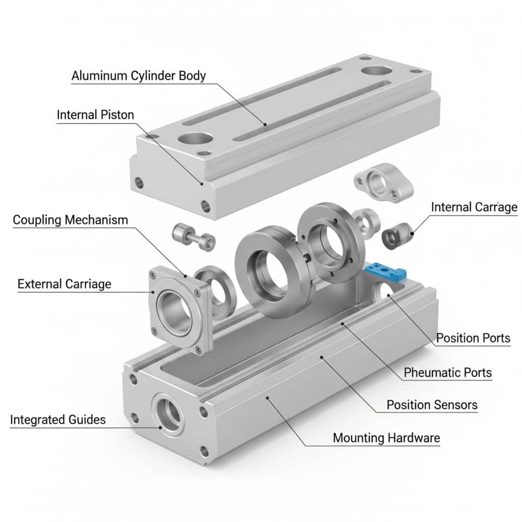
Cylinder Body Construction
The cylinder body forms the heart of the rodless cylinder system. Most manufacturers use extruded aluminum profiles for optimal strength-to-weight ratio and corrosion resistance.
The internal bore requires precision machining to achieve surface finishes between 0.4 to 0.8 Ra1. This smooth finish ensures proper seal performance and extends component life.
Wall thickness varies based on bore size and operating pressure. Standard designs handle up to 10 bar operating pressure with appropriate safety factors built in.
Internal Piston Assembly
The internal piston converts pneumatic pressure into linear force. High-quality pistons use lightweight aluminum construction to minimize moving mass and enable faster acceleration.
Piston seals create the pressure boundary between cylinder chambers. We typically use polyurethane or NBR seals depending on operating conditions and media compatibility.
Magnetic elements embedded in the piston create the coupling force. Neodymium rare earth magnets provide the strongest coupling in the smallest package.
External Carriage System
The external carriage rides on precision linear guides and carries your application load. Carriage design affects system stiffness and load capacity.
| Component | Material Options | Typical Size Range | Key Features |
|---|---|---|---|
| Cylinder Body | Aluminum, Anodized | 20-100mm bore | Corrosion resistant |
| Internal Piston | Aluminum, Steel | Matches bore size | Lightweight design |
| External Carriage | Aluminum, Steel | 50-200mm length | High stiffness |
| Linear Guides | Hardened Steel | Various profiles | Precision motion |
| Magnets | Neodymium | Grade N42-N52 | Temperature stable |
Linear Guide Integration
Integrated linear guides eliminate the need for external guide systems. This saves space and reduces installation complexity while ensuring proper alignment.
Ball bearing guides provide the smoothest operation and highest precision. They suit applications requiring positioning accuracy within 0.1mm.
Roller bearing guides handle higher loads while maintaining good precision. They work well for heavy-duty applications with moderate accuracy requirements.
Slide bearing guides offer the most economical solution for basic applications. They provide adequate performance for simple positioning tasks.
Pneumatic Port Configuration
Air ports connect the compressed air supply to the cylinder chambers. Port sizing affects flow capacity and operating speed.
Standard port sizes range from G1/8 to G1/2 depending on cylinder bore size. Larger ports enable faster operation but require higher flow capacity.
Port location options include end ports, side ports, or both. Side ports enable more compact installations in tight spaces.
Position Sensing Systems
Magnetic sensors detect piston position through the non-magnetic cylinder wall. Reed switches2 provide simple on/off position feedback.
Hall effect sensors3 offer more precise position detection with analog output capability. They enable closed-loop position control systems.
External sensors on the carriage provide the highest accuracy. Linear encoders can achieve positioning resolution down to micrometers.
How Does the Magnetic Coupling System Work?
The magnetic coupling system transfers pneumatic force without physical contact, creating clean and maintenance-free operation.
Magnetic coupling uses powerful neodymium magnets in both internal piston and external carriage to transfer force through the non-magnetic cylinder wall, achieving 85-95% efficiency without mechanical wear.
Magnetic Field Principles
Permanent magnets create a magnetic field that passes through the aluminum cylinder wall. The magnetic attraction between internal and external magnet assemblies transfers force directly.
Magnetic field strength decreases with distance. The air gap between internal and external magnets critically affects coupling strength and efficiency.
Magnet orientation affects coupling characteristics. Radial magnetization provides uniform coupling around the cylinder circumference.
Coupling Force Calculation
Maximum coupling force depends on magnet strength, air gap distance, and magnetic circuit design. Typical systems achieve 200-2000N coupling force.
Coupling efficiency ranges from 85-95% depending on design quality. Higher efficiency systems transfer more pneumatic force to the load.
Safety factors prevent coupling slip under normal loads. Overload protection occurs when applied forces exceed magnetic coupling capacity.
Temperature Effects
Magnet strength decreases with increasing temperature. Neodymium magnets lose approximately 0.12% strength per degree Celsius.
Operating temperature range affects magnet grade selection. Standard grades work to 80°C, while high-temperature grades handle 150°C.
Temperature compensation may be required for critical applications. This ensures consistent performance across temperature variations.
Magnetic Circuit Optimization
Pole piece design concentrates magnetic flux for maximum coupling efficiency. Proper pole piece geometry increases force transfer capability.
Back iron provides a return path for magnetic flux. Adequate back iron thickness prevents magnetic saturation and maintains coupling strength.
Air gap uniformity ensures consistent coupling around the cylinder. Manufacturing tolerances must maintain proper magnetic alignment.
What Makes Rodless Cylinders Different from Traditional Ones?
Rodless cylinders solve fundamental problems that limit traditional rod cylinder performance in modern automation systems.
Rodless cylinders eliminate exposed rods, reducing space requirements by 50%, preventing contamination accumulation, eliminating buckling issues, and providing superior side load handling through integrated guides.
Space Efficiency Comparison
Traditional cylinders require clearance for full rod extension plus cylinder body length. Total space needed equals stroke length plus cylinder length plus safety clearance.
Rodless designs only need stroke length plus minimal end clearances. This typically saves 40-60% of installation space compared to traditional cylinders.
Compact installations enable higher machine density and better space utilization. This directly impacts production capacity and facility costs.
Contamination Resistance
Exposed piston rods collect dust, debris, and process materials. This contamination causes seal wear, binding, and eventual failure.
Rodless designs have no exposed moving parts. The sealed construction prevents contamination entry and eliminates cleaning requirements.
Food processing applications particularly benefit from contamination resistance. Sealed designs meet strict hygiene requirements without modification.
Structural Advantages
Long-stroke traditional cylinders suffer from rod buckling under side loads. Critical buckling load follows Euler’s formula4: Fcr = π²EI/(KL)².
Rodless cylinders eliminate buckling concerns entirely. The internal piston cannot buckle, allowing unlimited stroke lengths within practical limits.
Side load capacity increases dramatically with integrated guides. Guide systems handle radial loads up to several thousand Newtons.
| Performance Factor | Traditional Cylinder | Rodless Cylinder | Improvement |
|---|---|---|---|
| Space Required | 2x stroke + body | 1x stroke only | 50% reduction |
| Max Stroke Length | 2-3 meters typical | 6+ meters possible | 200% increase |
| Side Load Capacity | Very limited | Excellent | 10x improvement |
| Contamination Risk | High exposure | Fully sealed | 95% reduction |
| Maintenance Frequency | Weekly cleaning | Monthly inspection | 75% reduction |
Load Handling Capabilities
Traditional cylinders require external guides for any side loads. This adds cost, complexity, and space requirements to the installation.
Integrated guides in rodless cylinders handle side loads, moments, and off-center loading. This eliminates external guide requirements in most applications.
Combined loading analysis shows rodless cylinders handle complex force combinations better than traditional designs with external guides.
How Do You Control Speed and Position?
Proper control systems ensure your rodless air slide operates smoothly and precisely while meeting your application requirements.
Control rodless cylinder speed using flow control valves and pressure regulators, achieve positioning through various sensor types, and implement servo control for precise motion profiles and closed-loop operation.
Speed Control Methods
Flow control valves regulate air flow rate into and out of cylinder chambers. Flow rate directly affects piston velocity according to Q = A × V.
Meter-in control restricts air flow entering the cylinder. This provides smooth acceleration and good speed control under varying loads.
Meter-out control restricts exhaust air flow from the cylinder. This method provides better load control and smoother deceleration.
Bi-directional flow control enables independent speed adjustment for extend and retract motions. This optimizes cycle times for different loading conditions.
Pressure Control Systems
Pressure regulators maintain consistent operating pressure despite supply variations. Stable pressure ensures repeatable force output and speed.
Pressure switches provide simple position feedback based on chamber pressures. They detect end-of-stroke conditions reliably.
Proportional pressure control enables variable force output. This suits applications requiring different force levels during operation.
Position Sensing Technologies
Magnetic reed switches detect piston position through cylinder walls. They provide simple on/off signals for basic position control.
Hall effect sensors offer analog position feedback with higher resolution. They enable proportional position control and intermediate positioning.
Linear potentiometers on the external carriage provide continuous position feedback. They suit applications requiring precise positioning.
Optical encoders deliver the highest position resolution and accuracy. They enable servo control with sub-millimeter positioning capability.
Servo Control Integration
Servo valves provide proportional flow control based on electrical command signals. They enable precise velocity and position control.
Closed-loop control systems compare actual position with commanded position. Feedback control maintains accuracy despite load variations.
Motion controllers coordinate multiple axes and execute complex motion profiles. They integrate rodless cylinders into sophisticated automation systems.
PLC integration enables coordination with other machine functions. Standard communication protocols simplify system integration.
What Are the Different Types of Force Transfer Mechanisms?
Different force transfer mechanisms suit various applications and performance requirements in rodless pneumatic cylinder systems.
Rodless cylinders use magnetic coupling for clean applications, cable systems for high forces, band mechanisms for harsh environments, and mechanical linkages for maximum force transmission, each offering specific advantages.
Magnetic Coupling Systems
Magnetic coupling provides the cleanest operation with no physical connection between internal and external components. This eliminates wear and maintenance.
Coupling force ranges from 200-2000N depending on magnet size and configuration. Higher forces require larger magnets and increased system cost.
Slip protection prevents damage during overload conditions. The magnetic coupling automatically disengages when forces exceed design limits.
Temperature stability varies with magnet grade selection. High-temperature magnets maintain performance up to 150°C operating temperature.
Cable Force Transfer
Steel cable systems connect internal pistons to external carriages through sealed cable exits. They provide higher force capacity than magnetic systems.
Cable materials include stainless steel for corrosion resistance and aircraft cable for flexibility. Cable selection affects system life and performance.
Pulley systems redirect cable forces and may provide mechanical advantage. Proper pulley design minimizes friction and cable wear.
Sealing challenges exist where cables exit the cylinder. Dynamic seals must accommodate cable movement while preventing air leakage.
Band Mechanism Systems
Flexible steel bands transfer force through slots in the cylinder wall. They handle the highest forces and harshest environmental conditions.
Band materials include carbon steel, stainless steel, and special alloys. Material selection depends on environmental and force requirements.
Slot sealing prevents air leakage while allowing band movement. Advanced sealing systems minimize leakage without excessive friction.
Contamination tolerance is excellent since bands can push through debris. This suits applications in dusty or dirty environments.
Mechanical Linkage Systems
Direct mechanical connections provide positive force transfer without slippage. They offer maximum force transmission but increased complexity.
Linkage designs include rack-and-pinion, lever systems, and gear mechanisms. Selection depends on force requirements and space constraints.
Sealing complexity increases with mechanical penetrations through cylinder walls. Multiple dynamic seals may be required.
Maintenance requirements are higher due to mechanical wear and lubrication needs. Regular service maintains optimal performance.
| Transfer Type | Force Range | Environment Suitability | Maintenance Level | Best Applications |
|---|---|---|---|---|
| Magnetic | 200-2000N | Clean, moderate temp | Very low | Food, pharma, electronics |
| Cable | 500-5000N | General industrial | Low | Packaging, assembly |
| Band | 1000-8000N | Harsh, contaminated | Moderate | Heavy industry, mining |
| Mechanical | 2000-15000N | Clean, controlled | High | High-force applications |
How Do You Calculate Performance and Sizing?
Accurate performance calculations ensure proper rodless cylinder selection and optimal system performance for your specific application.
Calculate rodless cylinder performance using force equations (F = P × A × η), speed calculations (V = Q/A), acceleration analysis, and efficiency factors to determine sizing, air consumption, and expected performance.
Force Calculation Methods
Theoretical force equals air pressure times effective piston area: F = P × A. This gives maximum available force under ideal conditions.
Effective force accounts for friction losses and coupling efficiency: F_eff = P × A × η_coupling × η_friction. Typical overall efficiency ranges 75-90%.
Load analysis includes static weight, process forces, acceleration forces, and friction. All forces must be considered for proper sizing.
Safety factors should be applied to calculated loads. Recommended safety factors range from 1.5-2.5 depending on application criticality.
Speed and Cycle Time Analysis
Cylinder speed relates to air flow rate: V = Q/A, where velocity equals flow rate divided by effective area.
Acceleration time depends on net force and moving mass: t = (V × m)/F_net. Higher forces enable faster acceleration.
Cycle time includes acceleration, constant velocity, and deceleration phases. Total cycle time affects productivity and throughput.
Cushioning effects reduce speed near stroke ends. Cushioning distance typically ranges 10-50mm depending on speed and load.
Air Consumption Calculations
Air consumption per cycle equals cylinder volume times pressure ratio: V_air = cylinder_volume × (P_abs/P_atm).
Total system consumption includes losses through valves, fittings, and leakage. Losses typically add 20-30% to theoretical consumption.
Compressor sizing must handle peak demand plus system losses. Adequate capacity prevents pressure drops during operation.
Energy cost analysis helps justify system optimization. Compressed air typically costs $0.02-0.05 per cubic meter.
Performance Optimization
Bore size selection balances force requirements with speed and air consumption. Larger bores provide more force but use more air.
Stroke length affects system cost and space requirements. Longer strokes may require larger guide systems and mounting structures.
Operating pressure optimization considers force needs and energy costs. Higher pressures reduce cylinder size but increase energy consumption.
Control system selection matches complexity to application requirements. Simple systems cost less but provide limited functionality.
What Are Common Applications for Rodless Air Slides?
Rodless cylinders excel in applications where space efficiency, contamination resistance, or long strokes are critical success factors.
Common rodless cylinder applications include packaging machinery, assembly automation, material handling systems, pick-and-place operations, and conveyor integration where compact design and reliable operation are essential.
Packaging Industry Applications
Packaging lines benefit from compact design and high-speed operation. Rodless air slides handle product positioning, carton manipulation, and conveyor integration efficiently.
Food packaging particularly benefits from contamination-resistant design. Sealed construction meets strict hygiene requirements without special modifications.
Pharmaceutical packaging requires clean operation and validation documentation. Our systems include material certificates and validation support packages.
High-speed packaging lines achieve cycle rates up to 300 per minute. Lightweight moving parts enable rapid acceleration and deceleration.
Assembly Automation Systems
Electronics assembly uses rodless cylinders for component placement and PCB handling. Clean operation prevents contamination of sensitive electronic components.
Automotive assembly applications include part insertion, fastener installation, and quality inspection positioning. Reliability is crucial for production continuity.
Medical device assembly requires precise positioning and contamination control. Validated systems meet FDA and ISO requirements5.
Multi-station assembly systems coordinate multiple rodless cylinders for complex operations. Synchronized motion optimizes cycle times and quality.
Material Handling Operations
Warehouse automation systems use rodless cylinders for sorting, diverting, and positioning operations. Reliable operation ensures high system availability.
Distribution centers benefit from high-speed operation and precise positioning. Accurate placement improves sorting efficiency and reduces errors.
Palletizing systems use multiple coordinated rodless cylinders for layer formation. Precise positioning enables optimal pallet patterns.
Automated storage systems require precise positioning for inventory management. Accuracy ensures correct item retrieval and storage.
Pick-and-Place Applications
Robotic integration uses rodless cylinders for additional motion axes. Extended reach improves robot workspace utilization and flexibility.
Vision-guided systems combine rodless cylinders with cameras for adaptive positioning. This handles product variations without reprogramming.
High-speed picking applications benefit from lightweight, fast-moving carriages. Reduced inertia enables rapid acceleration and precise stopping.
Gentle handling applications use controlled acceleration profiles. Smooth motion prevents product damage during handling operations.
| Application Area | Key Benefits | Typical Cycle Rate | Force Range | Stroke Length |
|---|---|---|---|---|
| Packaging | Speed, cleanliness | 100-300 cpm | 200-1500N | 100-1000mm |
| Assembly | Precision, reliability | 50-150 cpm | 300-2000N | 50-500mm |
| Material Handling | Load capacity, durability | 20-100 cpm | 500-5000N | 200-2000mm |
| Pick-and-Place | Speed, accuracy | 200-500 cpm | 100-1000N | 50-800mm |
What Maintenance and Troubleshooting Steps Are Required?
Proper maintenance ensures reliable operation and maximizes service life of your rodless pneumatic cylinder system.
Rodless cylinder maintenance includes regular air filter changes, guide lubrication, seal inspection, sensor cleaning, and performance monitoring to prevent failures and maintain optimal operation.
Preventive Maintenance Schedule
Daily checks include visual inspection for leaks, unusual noises, or erratic operation. Early detection prevents minor issues from becoming major failures.
Weekly maintenance includes air filter inspection and replacement if needed. Clean, dry air is essential for reliable operation and long seal life.
Monthly service includes guide lubrication, sensor cleaning, and performance verification. Regular service maintains optimal performance and prevents wear.
Annual overhaul includes seal replacement, internal inspection, and complete system testing. Scheduled overhauls prevent unexpected failures.
Common Troubleshooting Issues
Slow operation usually indicates restricted air flow or low pressure. Check filters, regulators, and flow control valve settings.
Erratic motion may result from contaminated air, worn seals, or sensor problems. Systematic diagnosis identifies the root cause.
Position errors can result from sensor misalignment, magnetic interference, or coupling slip. Proper diagnosis prevents recurring problems.
Excessive air consumption indicates internal leakage or system inefficiency. Leak detection and repair restore normal operation.
Seal Replacement Procedures
Seal replacement requires cylinder disassembly and proper tooling. Follow manufacturer procedures to prevent damage during service.
Seal selection depends on operating conditions and media compatibility. Use only approved replacement seals for reliable operation.
Installation requires proper seal orientation and lubrication. Incorrect installation causes premature failure and poor performance.
System testing after seal replacement verifies proper operation. Performance testing ensures the repair was successful.
Performance Monitoring
Force output monitoring detects coupling degradation or internal wear. Regular testing identifies problems before failure occurs.
Speed monitoring reveals flow restrictions or pressure problems. Consistent monitoring enables predictive maintenance.
Position accuracy testing verifies sensor operation and system alignment. Regular calibration maintains positioning accuracy.
Air consumption monitoring identifies efficiency problems and leakage. Trend analysis enables proactive maintenance planning.
Conclusion
Rodless air slides provide space-efficient, contamination-resistant linear motion through advanced coupling technology, making them essential for modern automation applications requiring reliability and performance.
FAQs About Rodless Air Slides
How does a rodless air cylinder work?
A rodless air cylinder works by using compressed air to move an internal piston connected to an external carriage through magnetic coupling or mechanical linkage, eliminating the exposed piston rod while providing smooth linear motion.
What are the main advantages of rodless cylinders over traditional ones?
Rodless cylinders save 50% installation space, resist contamination with sealed design, handle unlimited stroke lengths without buckling, and provide excellent side load capacity through integrated linear guides.
How much force can a magnetic rodless cylinder provide?
Magnetic rodless cylinders typically provide 200-2000N force output depending on bore size and magnet configuration, with coupling efficiency ranging from 85-95% of theoretical pneumatic force.
What maintenance do rodless air slides require?
Rodless air slides require minimal maintenance including regular air filter changes, monthly guide lubrication, annual seal inspection, and sensor cleaning to maintain optimal performance and reliability.
Can rodless cylinders handle side loads and moments?
Yes, rodless cylinders excel at handling side loads up to several thousand Newtons and moments through their integrated precision linear guide systems, eliminating the need for external guides.
How do you control the speed of a rodless pneumatic cylinder?
Control rodless cylinder speed using flow control valves on air supply lines, with meter-in control for smooth acceleration and meter-out control for better load handling and deceleration.
What applications are best suited for rodless air slides?
Rodless air slides work best in packaging machinery, assembly automation, material handling, pick-and-place operations, and any application requiring space efficiency, contamination resistance, or long stroke lengths.
-
Learn how Ra (Roughness Average) is defined and measured as a key parameter for engineering surface finish. ↩
-
Explore the working principle of reed switches and how they are used as magnetically-activated sensors. ↩
-
Understand the physics of the Hall effect and its application in creating precise, non-contact position sensors. ↩
-
Review the derivation and application of Euler’s formula for calculating the critical buckling load in structural columns. ↩
-
Access an overview of the ISO requirements for quality management systems in the medical device industry. ↩
