

Engineers struggle with cylinder height measurements when replacing rodless pneumatic cylinder components. Incorrect height calculations cause installation failures and expensive project delays.
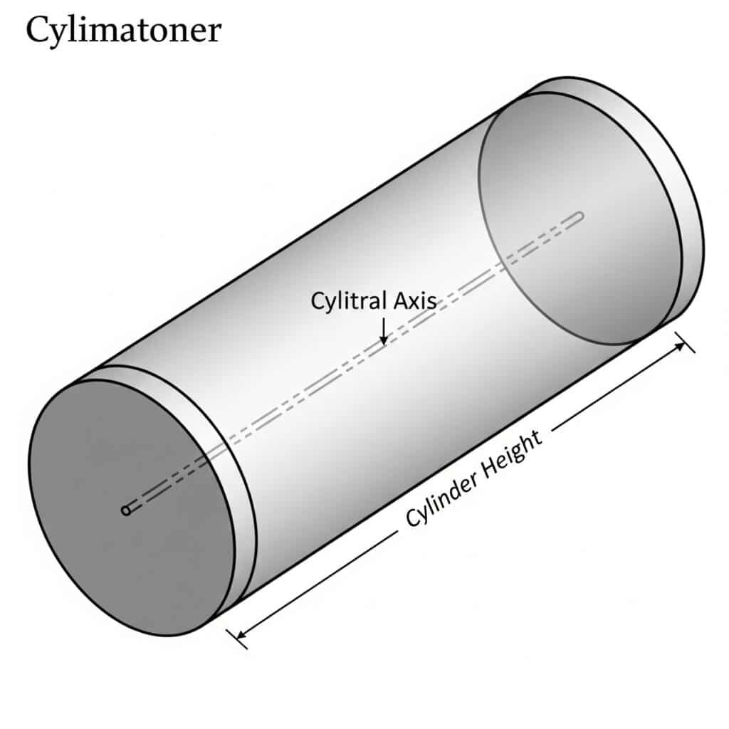
Cylinder height is the perpendicular distance between the two circular bases, measured as the straight-line length along the cylinder’s axis using calipers or measuring tape.
Yesterday, I helped Roberto, a maintenance engineer from Italy, who ordered wrong-sized guided rodless cylinder1 parts because he confused stroke length with total cylinder height.
Table of Contents
- What is Cylinder Height in Rodless Pneumatic Systems?
- How Do You Measure Cylinder Height Accurately?
- What’s the Difference Between Height and Stroke Length?
- How Does Height Affect Rodless Cylinder Performance?
What is Cylinder Height in Rodless Pneumatic Systems?
Cylinder height represents the total axial length of your rodless cylinder housing, measured from one end cap to the other along the central axis.
Cylinder height is the straight-line distance between both circular end faces, measured parallel to the cylinder’s central axis, regardless of mounting orientation or stroke position.
Height Definition Components
Physical Boundaries
- Start point: First circular end face
- End point: Second circular end face
- Measurement path: Straight line along central axis
- Exclusions: Mounting hardware, fittings, connections
Geometric Relationship
Height = Axial Length
- Independent of diameter: Height measurement unaffected by bore size
- Parallel to axis: Always measured along cylinder centerline
- Perpendicular to bases: 90° angle to circular faces
- Consistent orientation: Same regardless of mounting position
Height vs Other Dimensions
| Dimension | Definition | Measurement Direction | Application |
|---|---|---|---|
| Height | End-to-end length | Along cylinder axis | Total space requirements |
| Diameter | Circular width | Across cylinder face | Bore sizing, force calculations |
| Radius | Half diameter | Center to edge | Surface area calculations |
| Stroke | Piston travel | Within cylinder height | Working range |
Standard Height Categories
Compact Cylinders
- Height range: 50mm – 200mm
- Applications: Space-constrained installations
- Typical uses: Packaging machinery, small automation
- Stroke limitations: 25mm – 100mm typical
Standard Cylinders
- Height range: 200mm – 800mm
- Applications: General industrial automation
- Typical uses: Assembly lines, material handling
- Stroke options: 100mm – 500mm range
Extended Cylinders
- Height range: 800mm – 2000mm+
- Applications: Long-stroke requirements
- Typical uses: Large machinery, positioning systems
- Stroke capabilities: 500mm – 1500mm+
Height Measurement Importance
Installation Planning
I use height measurements for:
- Space allocation: Ensuring adequate clearance
- Mounting design: Bracket and support sizing
- System integration: Component fit verification
- Maintenance access: Service space requirements
Component Selection
Height affects:
- Stroke length: Maximum travel distance
- Force output: Pressure vessel capacity
- Mounting options: Available connection types
- Cost factors: Material and manufacturing expenses
How Do You Measure Cylinder Height Accurately?
Accurate height measurement requires proper tools and techniques to ensure correct rodless cylinder sizing and replacement part compatibility.
Use a steel ruler or digital calipers to measure the straight-line distance between both end faces, ensuring the measurement path stays parallel to the cylinder axis.
Essential Measurement Tools
Digital Calipers2 (Recommended)
- Accuracy: ±0.02mm precision
- Range: Up to 300mm for most applications
- Features: Digital display, zero reset function
- Advantages: Most precise for shorter cylinders
Steel Measuring Tape
- Accuracy: ±0.5mm typical
- Range: Unlimited length capability
- Features: Rigid first 12 inches, flexible extension
- Best for: Long rodless cylinders over 300mm
Precision Steel Ruler
- Accuracy: ±0.1mm when used properly
- Range: 300mm, 500mm, 1000mm options
- Features: Etched graduations, hardened edges
- Applications: Medium-length measurements
Step-by-Step Measurement Process
Preparation Steps
- Clean cylinder surfaces: Remove dirt, oil, debris
- Position cylinder: Stable, accessible orientation
- Check tool calibration: Verify measurement accuracy
- Plan measurement path: Identify start and end points
Measurement Technique
- Locate first end face: Identify circular boundary
- Position measuring tool: Align with cylinder axis
- Extend to second end: Maintain parallel alignment
- Read measurement: Record to appropriate precision
- Verify reading: Take second measurement for confirmation
Common Measurement Challenges
Access Limitations
- Mounted cylinders: Limited measurement angles
- Tight spaces: Restricted tool positioning
- Connection interference: Fittings block access
- Solution: Use flexible measuring tape or offset tools
Alignment Issues
- Non-parallel measurement: Causes overestimation
- Angled positioning: Increases apparent length
- Curved measurement path: Inaccurate results
- Prevention: Use alignment guides or reference surfaces
Measurement Verification Methods
Cross-Check Techniques
- Multiple measurements: Take 3 readings minimum
- Different tools: Compare caliper vs tape results
- Reverse measurement: Measure from opposite end
- Reference comparison: Check against specifications
Error Detection
- Inconsistent readings: ±1mm variation acceptable
- Systematic errors: All readings high or low
- Tool problems: Calibration or damage issues
- Environmental factors: Temperature, vibration effects
Special Measurement Situations
Magnetic Rodless Cylinders
- External housing: Measure complete assembly height
- Internal components: Separate measurements may be needed
- Magnetic coupling: Account for end cap variations
- Access considerations: Magnetic attraction affects tools
Guided Rodless Cylinders
- Guide rail inclusion: Measure cylinder body only
- Mounting bracket exclusion: Cylinder height separate
- Linear bearing clearance: Affects measurement access
- Reference datum: Use cylinder centerline
Double Acting Rodless Cylinders
- Port locations: Don’t include in height measurement
- End cap variations: Different thicknesses possible
- Cushioning features: May extend beyond basic height
- Specification verification: Check manufacturer drawings
Last month, I helped Michelle, a procurement specialist from Canada, who measured her rodless air cylinder height incorrectly by including the mounting brackets. This error caused a 3-week delay when replacement parts didn’t fit the existing installation.
What’s the Difference Between Height and Stroke Length?
Understanding the distinction between cylinder height and stroke length prevents costly ordering mistakes and ensures proper rodless pneumatic cylinder selection.
Cylinder height is the total external length of the housing, while stroke length is the internal distance the piston travels, typically 60-80% of total height.
Height vs Stroke Comparison
Cylinder Height
- Definition: Complete housing length
- Measurement: End cap to end cap
- Fixed dimension: Doesn’t change during operation
- Includes: All structural components
- Purpose: Space planning and mounting
Stroke Length
- Definition: Piston travel distance
- Measurement: Maximum internal movement
- Variable dimension: Changes during cylinder operation
- Excludes: End caps, cushioning, dead space
- Purpose: Work output and positioning range
Relationship Between Height and Stroke
Typical Ratios
| Cylinder Type | Height | Stroke | Ratio | Dead Space |
|---|---|---|---|---|
| Compact | 100mm | 60mm | 60% | 40mm |
| Standard | 300mm | 200mm | 67% | 100mm |
| Extended | 800mm | 600mm | 75% | 200mm |
| Long stroke | 1500mm | 1200mm | 80% | 300mm |
Dead Space Components
- End caps: 15-25mm each end typical
- Cushioning: 5-15mm each end
- Sealing areas: 3-8mm allowances
- Safety margins: 5-10mm operational clearance
Calculation Methods
Stroke from Height
Approximate Stroke = Height × 0.7
- Conservative estimate: Accounts for most designs
- Verification needed: Check manufacturer specifications
- Application: Initial sizing estimates
Height from Stroke
Required Height = Stroke ÷ 0.7
- Minimum housing: Add safety factor
- Standard practice: Use 0.65-0.75 multiplier
- Custom applications: Consult engineering specifications
Practical Applications
System Design
I use height measurements for:
- Machine layout: Total space requirements
- Clearance planning: Obstacle avoidance
- Mounting design: Support structure sizing
- Maintenance access: Service space allocation
Performance Planning
I use stroke measurements for:
- Work envelope: Actual positioning range
- Force calculations: Effective working area
- Speed analysis: Travel time requirements
- Application suitability: Task capability assessment
Common Confusion Sources
Specification Sheets
- Multiple dimensions: Height, stroke, overall length listed
- Mounting variations: Different configurations shown
- Optional features: Cushioning, sensors affect dimensions
- Standard vs custom: Specifications may vary
Ordering Mistakes
- Wrong dimension used: Height ordered instead of stroke
- Incomplete specifications: Missing critical measurements
- Assumption errors: Standard ratios don’t always apply
- Communication gaps: Technical terms misunderstood
Verification Techniques
Specification Cross-Check
- Manufacturer data: Confirm both dimensions
- Drawing review: Verify dimensional relationships
- Sample inspection: Physical measurement if available
- Engineering consultation: Technical support confirmation
Field Measurement
- Existing cylinders: Measure both height and stroke
- Stroke measurement: Extend cylinder fully, measure travel
- Height verification: Confirm housing dimensions
- Documentation: Record both measurements clearly
When I worked with David, a maintenance supervisor from Germany, he initially confused stroke length with cylinder height when ordering replacement guided rodless cylinder components. This mistake would have cost his company €3,200 and caused a 2-week production delay if we hadn’t caught the error during our technical review.
How Does Height Affect Rodless Cylinder Performance?
Cylinder height directly influences stroke capability, structural strength, mounting requirements, and overall system performance in rodless pneumatic applications.
Longer cylinder height provides greater stroke length and improved load distribution but increases deflection risk, mounting complexity, and system costs.
Performance Impact Areas
Stroke Capability
- Maximum travel: Height determines available stroke
- Working range: Effective positioning envelope
- Application suitability: Task-specific requirements
- Flexibility: Multiple positioning options
Structural Considerations
- Deflection3 resistance: Height-to-diameter ratio critical
- Load capacity: Longer cylinders handle less side load
- Mounting support: Additional brackets needed for long cylinders
- Vibration sensitivity: Height affects natural frequency4
Height-to-Diameter Ratios
Optimal Ratios
| Application | Height:Diameter | Stability | Performance |
|---|---|---|---|
| Compact | 2:1 to 4:1 | Excellent | High speed |
| Standard | 4:1 to 8:1 | Good | Balanced |
| Extended | 8:1 to 12:1 | Fair | High force |
| Long stroke | 12:1+ | Poor | Requires support |
Support Requirements
- Ratios above 10:1: Intermediate supports recommended
- Side loading: Additional mounting points needed
- Deflection control: Guide rails or linear bearings
- Vibration damping: Isolation mounts beneficial
Force and Speed Relationships
Force Output
Force = Pressure × Bore Area
- Height independence: Force unaffected by cylinder length
- Pressure consistency: Maintained throughout stroke
- Load distribution: Longer stroke spreads forces
- Application advantage: Consistent power delivery
Speed Characteristics
- Acceleration: Longer cylinders have more internal volume
- Flow requirements: Higher air consumption for long strokes
- Response time: Increased with cylinder height
- Efficiency: Optimum speed varies with length
Installation Considerations
Space Requirements
- Linear space: Height plus stroke clearance needed
- Mounting footprint: Support structure sizing
- Access requirements: Maintenance and service space
- Integration challenges: Fitting within existing machinery
Mounting Methods
- Single-point mounting: Suitable for compact cylinders only
- Multi-point support: Required for extended lengths
- Guide systems: Necessary for long-stroke applications
- Alignment critical: Prevents binding and wear
Cost-Performance Analysis
Initial Costs
- Material costs: Proportional to cylinder height
- Manufacturing complexity: Longer cylinders cost more
- Mounting hardware: Additional supports increase expense
- Installation time: More complex setup procedures
Operating Costs
- Air consumption: Higher for longer strokes
- Maintenance frequency: May increase with complexity
- Downtime risk: More components mean more failure points
- Energy efficiency: Varies with application optimization
Height Selection Guidelines
Application-Based Selection
- Required stroke: Primary determining factor
- Space constraints: Maximum allowable height
- Load requirements: Side load vs stroke length trade-off
- Speed needs: Response time considerations
- Cost budget: Balance performance vs expense
Engineering Calculations
- Deflection analysis: Beam theory5 for long cylinders
- Natural frequency: Avoid resonance conditions
- Safety factors: Account for dynamic loading
- Support spacing: Minimize deflection between mounts
Real-World Examples
Packaging Machinery
- Typical height: 150-300mm
- Stroke requirement: 100-200mm
- Performance priority: High speed, compact size
- Solution: Guided rodless cylinders with 4:1 ratio
Material Handling
- Typical height: 500-1200mm
- Stroke requirement: 300-800mm
- Performance priority: Force and reliability
- Solution: Double acting rodless cylinders with intermediate supports
When I advised Patricia, a design engineer from France, on selecting cylinder height for her automated assembly line, we optimized the height-to-diameter ratio to achieve 40% faster cycle times while maintaining the required 2000N force output.
Conclusion
Cylinder height is the total axial length between end faces, different from stroke length. Accurate measurement ensures proper rodless cylinder selection, installation fit, and optimal performance.
FAQs About Cylinder Height
How do you measure cylinder height correctly?
Use digital calipers or steel measuring tape to measure the straight-line distance between both circular end faces along the cylinder’s central axis. Clean surfaces first and take multiple measurements for accuracy verification.
What’s the difference between cylinder height and stroke length?
Cylinder height is the total external housing length from end to end, while stroke length is the internal piston travel distance, typically 60-80% of total height depending on end cap and cushioning space.
Why is accurate cylinder height measurement important?
Accurate height measurement ensures proper space allocation, correct mounting hardware selection, and compatibility with existing installations. Incorrect measurements cause costly delays and component incompatibility in rodless pneumatic systems.
How does cylinder height affect performance?
Longer cylinder height provides greater stroke capability but increases deflection risk and mounting complexity. Height-to-diameter ratios above 10:1 typically require intermediate support to maintain structural stability and performance.
What tools are best for measuring cylinder height?
Digital calipers provide highest accuracy (±0.02mm) for cylinders under 300mm. Steel measuring tape works best for longer rodless cylinders. Always verify measurements with multiple readings using calibrated tools.
-
Learn about the construction and advantages of guided rodless cylinders. ↩
-
Review a step-by-step guide on how to accurately use and read digital calipers. ↩
-
Understand the engineering principles of deflection in structural beams. ↩
-
Explore the concept of natural frequency and its importance in avoiding mechanical resonance. ↩
-
Discover the fundamentals of beam theory used to calculate stress and deflection. ↩
