

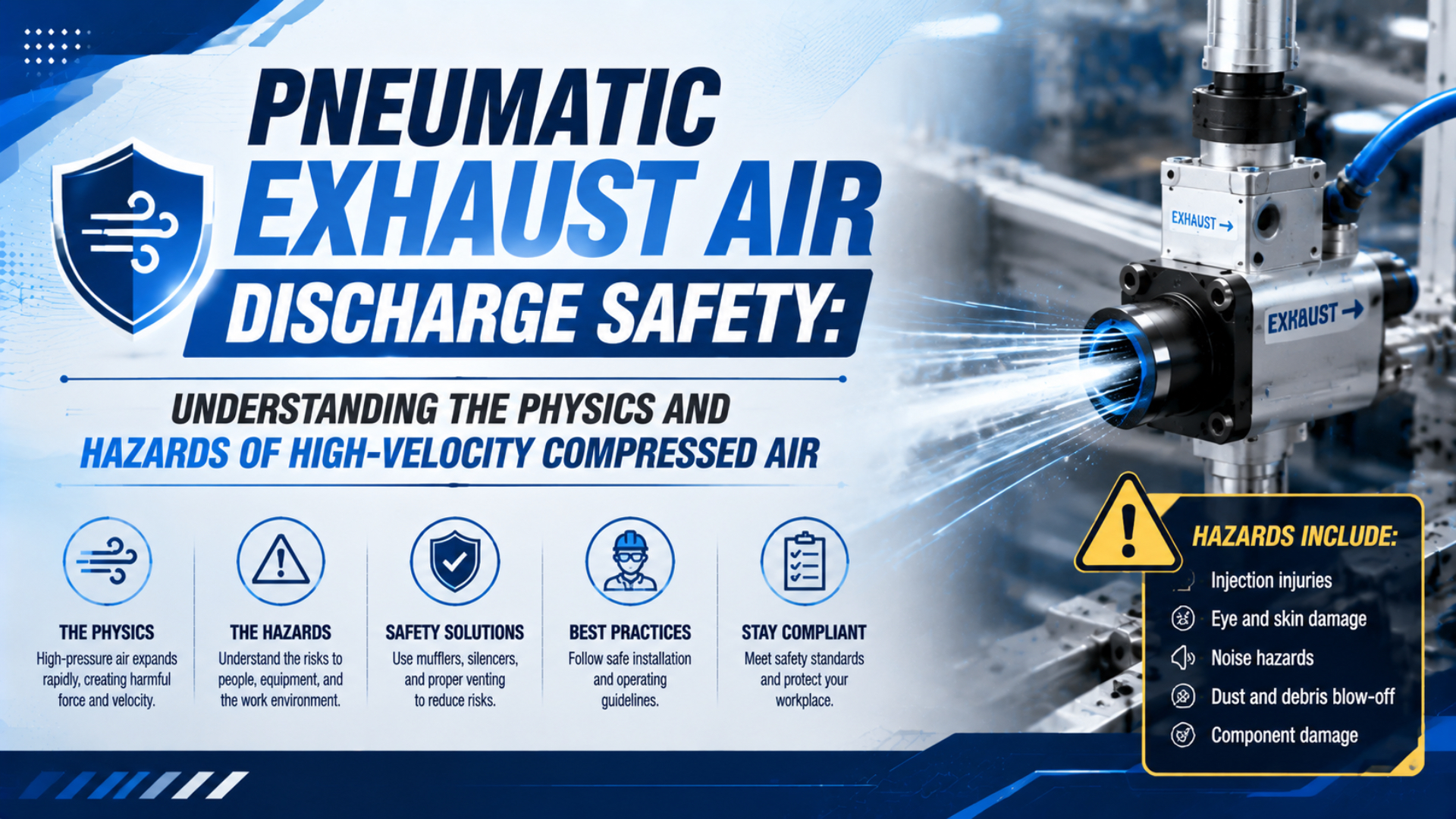
Pneumatic exhaust is safe only when its discharge direction, accessible energy, noise, debris, back pressure, and residual machine motion have all been controlled. Supply pressure alone cannot predict jet velocity, sound level, or injury risk. The exhaust restriction, upstream volume, valve geometry, duty cycle, outlet location, and surrounding equipment all matter.
The first design decision is to identify the discharge scenario. A fixed valve exhaust is not the same as an air gun used for cleaning. A quick exhaust valve is not a safety-rated dump valve. A speed-control muffler is not automatically acceptable on a safety exhaust. Treating these devices as interchangeable creates dangerous assumptions.
For a defensible review, trace each exhaust path from the pressurized volume to its final outlet, estimate the possible flow, apply guarding and noise controls, and then test the installed machine. ISO 4414 provides the system-level pneumatic safety framework, while OSHA rules define specific US obligations for compressed-air cleaning, occupational noise, and hazardous-energy control.
Key Takeaways
- OSHA’s 30 psi rule applies to compressed-air cleaning, not every fixed exhaust.
- Ideal air reaches its choked-flow threshold near a 0.528 absolute pressure ratio.
- Quick exhaust, safety exhaust, silencing, and meter-out control perform different functions.
- Validate accessible jets, noise, back pressure, residual pressure, and motion on the installed machine.
Four Exhaust Scenarios That Must Not Be Confused
OSHA limits compressed air used for cleaning to less than 30 psi unless it is reduced to that pressure at a blocked nozzle, and it still requires effective chip guarding and personal protective equipment. That narrow rule is one reason the four discharge scenarios below must be assessed separately. (OSHA 29 CFR 1910.242(b))
| Discharge scenario | Purpose | Main design concern | Suitable verification |
|---|---|---|---|
| Fixed valve or actuator exhaust | Release working air during normal cycling | Accessible jet, noise, debris, back pressure, repeated exposure | Outlet inspection, cycle test, sound survey, pressure measurement where needed |
| Cleaning or blow-off nozzle | Deliberately direct air at a surface | Blocked-nozzle pressure, chips, eye and skin exposure, misuse | Nozzle specification, blocked-end test, guarding and work-practice review |
| Quick exhaust valve | Vent an actuator chamber close to the port | High local flow, outlet direction, noise, contamination | Stroke-time test, downstream pressure check, outlet risk assessment |
| Safety exhaust or dump valve | Remove pneumatic energy as part of a safety function | Fault response, residual pressure, stop time, trapped energy | Safety-function validation and measured pressure-decay test |
A fixed exhaust port may cycle thousands of times per shift without anyone touching it. Its risk depends on where the outlet points, whether people can reach it, what contaminants can be entrained, and how multiple sources combine. Moving the outlet behind a guard or routing it to a controlled discharge point can be more reliable than relying on a warning label.
A cleaning nozzle is intentionally manipulated near people and workpieces. Its control measures therefore include the specific OSHA pressure rule, chip guarding, personal protective equipment, and safer alternatives such as vacuum cleaning where practical. Applying the same 30 psi figure to an actuator exhaust port does not characterize that port’s transient compressible flow.
How Does Pressure Ratio Create Choked Exhaust Flow?
ISO 6358-1 defines steady-state flow-rate characteristics for pneumatic components using parameters such as sonic conductance and critical back-pressure ratio. For ideal air with a specific heat ratio of about 1.4, the corresponding theoretical downstream-to-upstream absolute pressure ratio is approximately 0.528, not a fixed gauge-pressure threshold.
For an ideal gas, choking begins when:
where (P_1) is upstream absolute pressure, (P_2) is downstream absolute pressure, and (\gamma) is the ratio of specific heats. With air at (\gamma \approx 1.4), the right-hand side is about 0.528. A chamber exhausting from 7 bar absolute to 1 bar absolute is therefore well below the ideal critical ratio.
Choked flow means the mass flow cannot be increased further by lowering downstream pressure while the upstream state and restriction remain unchanged. The sonic condition occurs at the controlling restriction. It does not mean every point in the port, pipe, or free jet travels at the local speed of sound.
Real valves, fittings, silencers, and tubing have geometry-dependent losses. Manufacturer flow data based on ISO 6358 parameters is more useful than an ideal-orifice equation for final component selection. The ideal equation still helps explain why reducing atmospheric back pressure does not indefinitely increase mass flow.
What Hazards Can a Fixed Pneumatic Exhaust Port Create?
The UK Health and Safety Executive identifies bodily entry, skin penetration, and particles blown into the eyes as serious compressed-air hazards. Its guidance also warns that contaminated compressed air can introduce additional substances into an injury. These mechanisms support guarding accessible outlets, but they do not justify an invented universal velocity threshold. (HSE HSG39)
Direct air and entrained debris
Never use a fixed outlet that directs a concentrated jet toward an operator station, aisle, maintenance access point, sensor, electrical enclosure, or loose material. An air stream can mobilize chips, dust, scale, water, or oil carried from the system. A shield or diffuser should contain the foreseeable path without creating a new ricochet path.
Occupational noise
The sound from an exhaust event depends on mass flow, restriction geometry, pressure ratio, duration, repetition rate, nearby surfaces, and the number of sources operating together. A supply-pressure-to-decibel lookup table cannot capture these variables. Measure the complete machine at representative production conditions and evaluate worker exposure, not just a single valve on a bench.
Back pressure and cross-coupling
A shared exhaust manifold can restrict flow or transmit pressure to another branch. The result may be slower motion, failed release, or unintended repressurization. This is back pressure or pneumatic cross-coupling, not pressure intensification. Size the common line for credible simultaneous flow, prevent reverse interaction where required, and measure branch pressure during the worst operating sequence.
Cold surfaces, moisture, and icing
Rapid expansion lowers local gas temperature. Moisture can condense or freeze when the air supply is wet and duty is high. Ice or condensate may restrict a silencer or valve and change the pressure-decay time. The remedy begins with suitable air preparation, drainage, correctly selected components, and inspection under the actual ambient conditions.
Ordinary compressed air does not create a generic oxygen-displacement hazard merely because it exhausts. Atmosphere assessment becomes relevant when the working gas is not air, the source can be contaminated, or discharge occurs in a confined space where the specific gas and ventilation conditions require analysis.
OSHA, ISO 4414, and the Limits of the 30 psi Rule
US rules contain two numbers that are often conflated: OSHA’s cleaning rule uses 30 psi, while its hearing-conservation action level begins at an 8-hour time-weighted average of 85 dBA. Neither number is an instant pass-fail limit for every pneumatic exhaust component. (OSHA 1910.242; OSHA 1910.95)
The cleaning rule applies when compressed air is used for cleaning. OSHA requires pressure below 30 psi and effective chip guarding and personal protective equipment. OSHA interpretations explain that an approved safety nozzle may meet the pressure condition by limiting static pressure at the blocked tip. It remains necessary to control flying material and worker exposure.
For occupational noise, 85 dBA is the 8-hour action level for a hearing-conservation program under the general-industry standard. The permissible exposure table begins at 90 dBA for 8 hours and allows less time as level rises. Short exhaust impulses, overlapping machines, and reflections therefore need a time-based exposure assessment rather than a catalog sound figure alone.
NIOSH recommends controlling hazardous noise at the source or along its path before relying on hearing protection. In pneumatic systems, that hierarchy can include lower required pressure, reduced demand, quieter valve and nozzle geometry, remote discharge, enclosures, diffusers, and properly sized silencers.
ISO 4414 supplies broader principles for the design, construction, modification, installation, use, and maintenance of pneumatic systems. It does not turn one pressure or velocity number into universal compliance. The machine risk assessment still has to connect the identified hazard to engineered controls and validation evidence.
How Do Bore, Stroke, and Dead Volume Affect Exhaust Quantity?
A 50 mm bore with a 1,000 mm stroke has a geometric swept volume of about 1.96 L, five times the same bore at a 200 mm stroke. That calculation explains why long stroke can matter, but it is not yet the standard-air consumption or the instantaneous exhaust flow. (ISO 4414 system context)
For a full-bore chamber:
where (D) is bore and (L) is stroke. For the rod-side chamber of a conventional cylinder, use the annular area after subtracting rod area. Add port, tube, cushion, and other dead volumes when their contribution matters.
The amount of free air released is greater than the geometric chamber volume because the chamber is pressurized. Converting to a reference condition requires absolute pressure and absolute temperature:
where (V_1), (P_1), and (T_1) describe the trapped chamber state, while (P_N) and (T_N) define the selected reference condition. State the reference explicitly because “normal,” “standard,” and “free air” values can use different conventions.
Exhaust quantity still does not determine peak flow by itself. The valve conductance, ports, fittings, tube length, silencers, downstream pressure, and opening profile govern how quickly that mass leaves. A large chamber vented through a small restriction may produce a longer event, while a smaller chamber through a local quick exhaust may produce a sharper peak.
Rodless cylinders do not automatically have greater volume than every rod cylinder. Bore, stroke, internal geometry, and dead volume determine the result. Long-stroke rodless applications often deserve attention because of their stroke, not because the absence of an external rod creates a universal multiplier. For motion-specific sizing, see the guide to valve flow and cylinder stroke time.
Exhaust Routing, Guarding, Diffusion, and Noise Control
Silencer performance is product-specific. For example, SMC’s AN series lists a 30 dB(A) noise-reduction effect under its stated test conditions, while Festo’s UC data lists model-dependent sound-pressure levels of 60 to 68 dB(A) at 6 bar and 1 m. These are selection inputs, not guaranteed machine readings. (SMC AN; Festo UC)
Use the control hierarchy in this order:
- Reduce avoidable energy and demand. Use only the pressure and flow the process needs. Eliminate leaks and unnecessary blow-off.
- Remove the outlet from the exposure zone. Route exhaust away from personnel, debris, sensitive equipment, and air intakes.
- Diffuse or contain the jet. Use a rated diffuser, enclosure, or guard that cannot become a projectile or collect dangerous pressure.
- Attenuate noise without defeating flow. Select a silencer from manufacturer flow and back-pressure data, then test cycle time and downstream pressure.
- Treat contaminated exhaust where necessary. Oil-removal units or separation systems need capacity for the actual flow and maintenance condition.
- Measure the installed result. Verify sound exposure, motion, and pressure decay with all normal accessories fitted.
Remote exhaust piping can move a hazard away from an operator, but it adds restriction and may transfer the problem to another location. Support the pipe mechanically, provide suitable drainage, protect the terminal outlet, and evaluate simultaneous flow if multiple valves share a header.
A silencer’s clean catalog flow is not its lifetime flow. Oil, water, dust, and seal debris can increase restriction. Inspection frequency should be based on measured back pressure, cycle-time drift, pressure-decay performance, visible contamination, and the manufacturer’s instructions, not an unsupported universal three-month or annual replacement interval. The detailed pneumatic muffler guide covers silencer construction and sizing.
Quick Exhaust, Safety Exhaust, and Meter-Out Control
ISO 4414 requires pneumatic hazards to be addressed across the system life cycle, while OSHA’s lockout rule requires stored or residual energy to be relieved, disconnected, restrained, or otherwise rendered safe. A fast-working quick exhaust valve can improve venting, but speed alone does not make it a safety device. (ISO 4414; OSHA 1910.147)
A quick exhaust valve is a local venting device mounted near an actuator so chamber air can bypass the directional valve and long return tube. This can shorten stroke time and reduce upstream back pressure. It also places a high-flow outlet near the machine, so its direction, accessibility, silencer capacity, and contamination exposure require review.
A safety exhaust valve is part of a defined safety function. Its architecture, diagnostic coverage, fault response, reset behavior, flow capacity, and integration must satisfy the machine’s required risk reduction. A normal quick exhaust valve should not be substituted simply because it vents rapidly. See the dedicated guide to integrating safety exhaust valves for architecture and validation depth.
Accessories on a safety exhaust path require particular care. Use only configurations allowed by the valve manufacturer. If a silencer, hose, manifold, or collection device is permitted, include it in the worst-case pressure-decay test, including the credible contaminated condition. A restriction that makes normal operation quieter can delay the safety function.
Meter-out flow control regulates actuator motion by restricting chamber exhaust. It is useful for stable speed control but is not a personnel-safety function. Closing a meter-out valve can also trap pressure or slow a dump. The motion circuit and safety exhaust architecture must be reviewed together, especially when the directional valve configuration has blocked centers or shared exhausts.
Dumping supply pressure does not necessarily prevent movement. A vertical load can fall, two cylinder chambers can retain unequal pressure, a check valve can trap a volume, and an accumulator or elastic mechanism can release stored energy. OSHA’s lockout appendix explicitly requires checking isolation and dissipating or restraining residual energy before servicing. (OSHA 1910.147 Appendix A)
How Should the Installed Exhaust Path Be Validated?
OSHA requires representative noise monitoring when information indicates employee exposure may equal or exceed an 8-hour average of 85 dBA. Exhaust safety validation likewise has to represent the real machine: production pressure, normal simultaneous cycles, fitted accessories, realistic contamination, and foreseeable operating modes. (OSHA 1910.95(d))
Use a staged acceptance test:
- Review the schematic and physical routing. Identify every exhaust, pilot vent, drain, relief, quick exhaust, safety dump, and trapped volume.
- Confirm component data. Check pressure range, flow characteristics, permitted accessories, media compatibility, temperature, and contamination limits.
- Inspect accessibility and direction. Test normal positions, setup access, fault recovery, cleaning, and maintenance access.
- Measure dynamic pressure where consequences matter. Monitor actuator chambers and shared manifolds through the worst simultaneous sequence.
- Measure pressure-decay time. Trigger the safety function at maximum credible volume and initial pressure. Confirm residual pressure and any residual motion.
- Conduct a representative sound survey. Include production rate, multiple machines, reflections, and worker duration. The article on pneumatic valve acoustic signatures explains why time history and measurement position matter.
- Repeat after a relevant change. A new silencer, longer hose, altered manifold, higher cycle rate, or revised supply pressure can invalidate the earlier result.
For flow estimates, separate model prediction from acceptance evidence. An ideal calculation can flag an undersized path, and choked-flow physics explains the limiting mechanism. Only a test of the installed configuration shows whether the machine reaches its required safe state within the specified time.
Inspection and RFQ Checklist
ISO 4414 covers pneumatic-system safety from design through use and maintenance, so an exhaust specification should define more than a port thread. The RFQ and inspection record should connect operating conditions, discharge location, permissible back pressure, noise objectives, maintenance state, and safety-function timing to measurable acceptance criteria. (ISO 4414)
Ask the supplier or machine builder for:
- working medium, supply range, ambient range, and air-quality requirement;
- actuator bore, rod diameter where applicable, stroke, dead volume, and cycle rate;
- valve flow data using ISO 6358 parameters or an equivalent documented test method;
- exhaust outlet location, orientation, thread, and permitted piping or silencer options;
- silencer flow and back-pressure data at the required condition;
- declared noise test pressure, distance, installation, and measurement method;
- maximum allowable actuator back pressure and required stroke time;
- safety-valve performance level or category documentation where applicable;
- maximum pressure-decay time and the point at which pressure is measured;
- behavior under loss of supply, loss of power, blocked exhaust, and component fault;
- inspection method for contamination, restriction, damage, and unauthorized modification.
During routine inspection, look for removed silencers, improvised tubing, plugged drains, unsupported outlets, oil staining, ice, damaged guards, rising cycle time, and changes in sound. A loud new exhaust can indicate a missing component or leak; a suddenly quiet one can indicate dangerous restriction. Investigate the change rather than treating sound alone as proof of safety.
Pneumatic Exhaust Safety FAQs
OSHA’s 30 psi cleaning rule and 85 dBA hearing-conservation action level answer different questions, while ISO 4414 addresses the broader pneumatic system. The following answers keep those boundaries explicit so a convenient catalog number is not mistaken for evidence that an installed exhaust path is safe. (OSHA 1910.242; OSHA 1910.95)
Is 30 psi a safe limit for every pneumatic exhaust port?
No. OSHA’s 30 psi provision applies to compressed air used for cleaning and also requires effective chip guarding and personal protective equipment. Fixed valve and actuator exhausts need a risk assessment based on their function, flow path, accessible jet, debris, noise, back pressure, and machine motion.
Is there a universal safe pneumatic exhaust velocity?
No. A single velocity does not capture nozzle geometry, distance, duration, repetition, entrained particles, sound, or accessibility. Control the outlet by routing, guarding, diffusion, and suitable hardware, then measure the installed machine. Do not use an unsupported value such as 30 m/s as a universal limit.
Can a silencer be installed on a safety exhaust valve?
Only when the safety-valve manufacturer permits that exact accessory or configuration. Include the silencer and any downstream piping in the safety-function validation and pressure-decay test. Consider credible contamination because added restriction can prevent the system from reaching its specified safe state in time.
Why can an actuator still move after the air supply is dumped?
Pressure may remain trapped behind check valves, closed flow controls, blocked-center valves, or seals. Gravity, springs, accumulators, and unequal chamber pressures can also move the mechanism. Lockout requires residual energy to be relieved, disconnected, restrained, or otherwise rendered safe before work begins.
Do rodless cylinders always create a larger exhaust hazard?
No. Exhaust quantity depends on bore, stroke, dead volume, pressure, and temperature, while peak flow also depends on the discharge path. Long-stroke rodless cylinders often contain substantial volume, but an equivalent or larger rod cylinder can present the same or greater hazard.
Sources and technical references
Technical claims are linked inline to ISO, OSHA, NIOSH, HSE, SMC, and Festo source pages so each requirement, example, and limitation can be checked in context.