

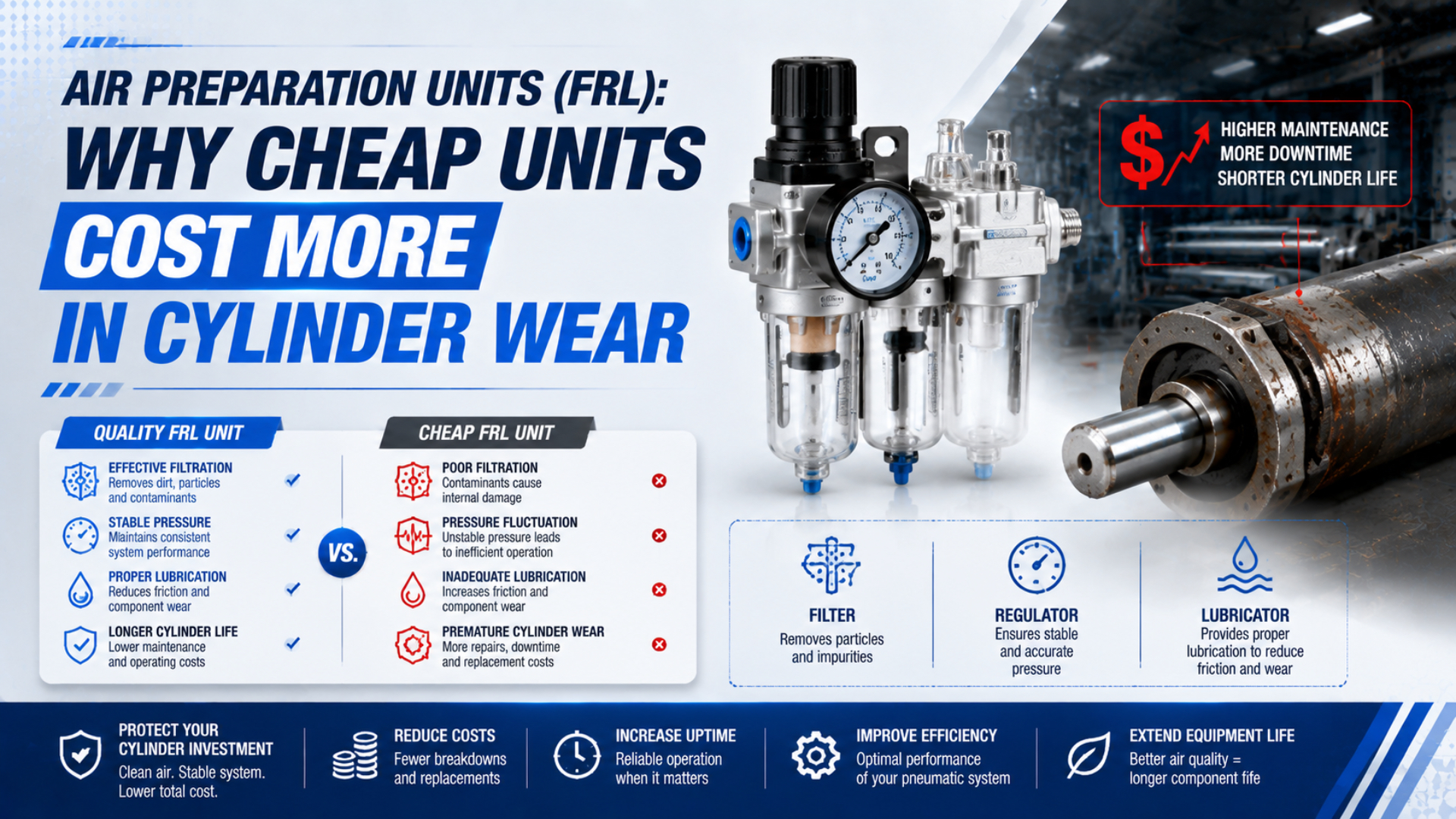
FRL cylinder wear is cylinder damage linked to contaminants, pressure-flow behavior, or incompatible lubrication in the point-of-use air path. Low-cost air preparation units become expensive only when an undocumented performance gap causes measurable downstream loss. Purchase price alone proves neither quality nor risk. That distinction matters because an FRL does not protect a cylinder by brand reputation or bowl count. It must deliver the required particle, water, and oil condition at a stated measurement point while maintaining usable pressure at peak flow. Evidence is what matters. Service must not introduce contamination or unsafe stored-energy exposure.
Key Takeaways
- CAGI recommends limiting total system pressure drop to 10% from compressor discharge to point of use.
- Compare FRLs using documented flow, pressure-drop, filtration, drain, and regulator data.
- Attribute cylinder wear before claiming savings, then calculate lifecycle cost from plant records.
This article focuses on cylinder-wear evidence and lifecycle cost. For broader component selection, use the air-source treatment unit guide. Internal filter, regulator, and lubricator mechanics belong in the separate FRL working-principle guide, which follows the air through each stage.
Low Purchase Price Is Not a Technical Specification
ISO 6953-1:2024 covers regulator literature for rated inlet pressures up to 25 bar and adjustable outlet pressures up to 16 bar. ISO 6953-2:2024 standardizes comparison tests. Those scopes show why a price or port thread cannot replace supplier pressure-flow, regulation, marking, and test data (ISO 6953-1, 2024; ISO 6953-2, 2024).
An inexpensive unit may be entirely suitable for a modest, clean branch. Higher price does not cure undersizing, chemical incompatibility, poor drain access, or an unnecessary lubricator. Cost alone is not the issue. The procurement question is not “cheap or premium?” It is “what performance is documented at the required condition?”
Use measurable attributes:
| Attribute | Evidence to request | Why it affects lifecycle cost |
|---|---|---|
| Rated flow | pressure-flow curve at stated inlet and outlet pressure | reveals droop and restriction during the real cycle |
| Filter performance | grade, efficiency basis, test method, initial and terminal pressure drop | separates a micron label from verified removal performance |
| Regulator behavior | flow characteristic, relieving type, hysteresis, pressure range | shows whether working pressure remains usable under demand |
| Drain system | manual, semi-automatic, or automatic behavior and service access | determines whether collected liquid is actually removed |
| Bowl and seal materials | chemical, temperature, and pressure compatibility | prevents stress cracking, swelling, leakage, and unsafe failure |
| Service support | element, seal, gauge, drain, and bowl availability | controls repair time and premature whole-unit replacement |
CE marking and RoHS status can matter for market access or restricted substances, but they do not establish filtration efficiency, regulator droop, service life, or cylinder protection. Ask for the performance characteristic that matches the failure risk.
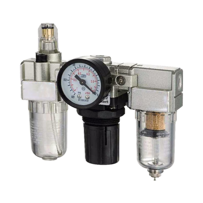
A three-module FRL can provide filtration, pressure regulation, and oil delivery, but each function still needs application-specific performance data.
Which FRL Defects Can Contribute to Cylinder Wear?
ISO 8573-1:2010 classifies compressed-air purity through three separate contaminant groups: particles, water, and oil. That three-part structure prevents a common diagnostic mistake. Clear bowls, 5 micrometer elements, and stable static pressure each verify only part of the air condition (ISO 8573-1, 2010).
Solid contamination can enter through the compressor intake, corroded distribution pipe, maintenance work, or a damaged filter element. Hard particles caught at a moving seal interface can scratch a bore or sealing lip. Debris leaves clues. Directional scoring or embedded particles support a contamination path, while general wear alone does not. Liquid water can support corrosion inside susceptible components and disturb lubricants. Water vapor is different. Normal bowl filters separate collected liquid but do not set pressure dew point. Repeated condensate therefore calls for a drain and dryer investigation, not simply a finer particle element. The pressure-dew-point guide explains that boundary.
Pressure control affects force, impact, leakage, and motion consistency. Trace the cycle. Undersized filter-regulators may starve a cylinder during flow even when the gauge looks correct at rest. Higher setpoints increase actuator force and end-of-stroke energy, but pressure alone does not prove seal extrusion. Check the component rating, clearance, temperature, material, and actual pressure trace. Lubrication can also fail in two directions. Insufficient approved lubricant can raise friction in equipment designed for line oil. Unnecessary or incompatible oil can wash factory grease, affect elastomers, contaminate a process, or obstruct exhaust devices. The downstream component manuals decide which condition applies.
| Observed damage | FRL-related hypothesis | Competing cause that must be checked |
|---|---|---|
| Long scratches on bore or seal | particle passage or contamination introduced during service | damaged tube, assembly debris, or worn guide |
| Internal rust or water staining | liquid-water carryover or failed drain | long shutdown, washdown ingress, or storage conditions |
| Swollen, soft, or brittle seal | incompatible oil or chemical carryover | ambient chemical exposure, heat, or wrong replacement material |
| Repeated rod-seal wear on one side | contamination at the rod interface | side load, misalignment, bent rod, or poor mounting |
| Harsh end impact | excessive pressure or unstable flow control | incorrect cushioning, speed, mass, or external stop |
| Several actuators slow together | shared FRL restriction or regulator droop | upstream supply loss or common exhaust restriction |
For failure-pattern interpretation, pair the air review with the industrial cylinder seal guide, while checking rodless-cylinder bands, guides, and alignment faults through a separate mechanical inspection.
How Can You Prove the FRL Caused the Wear?
The U.S. Department of Energy gives an example in which a regulator and upstream filter consume 20 psi, making the local components, not the distribution pipe, the correct repair target. Measure pressure at several points under flow before assigning cause (DOE Compressed Air Sourcebook, 2003).
Static readings are not enough.
Start by preserving the failed seal, wear band, rod, or cylinder tube. Photograph the damage before cleaning it. Record which actuators share the same FRL and whether their symptoms appeared together. If only one actuator fails repeatedly while every other device on the branch remains healthy, the FRL is still worth checking, but the evidence points more strongly toward a local mechanical or material problem. In our experience, the fastest diagnosis comes from synchronizing pressure readings with the exact motion that produces the complaint. An idle regulator gauge hides restrictions because little air is moving. Record pressure immediately before the FRL, immediately after it, and at the valve or actuator inlet during the same production event.
The flowing loss across the assembly is:
In this equation, is FRL pressure loss, is inlet pressure during the selected event, and is outlet pressure at the same time. Keep one pressure unit throughout. Compare the result with the selected model’s filter limit and pressure-flow curve, not with a universal number.
Treat causation as two independent questions: did the FRL fail an acceptance requirement, and does the failed requirement explain the observed wear pattern? A clogged filter can explain pressure sag but not automatically explain seal swelling. Incompatible oil can explain material change but not a one-sided wear band caused by side load.
What Does “5 Micron” Actually Tell You?
ISO 12500-3:2009 identifies two particulate-filter test ranges. The fine range is above 0.01 micrometer and below 5 micrometers; the coarse range extends from 5 to 40 micrometers. Standardized testing by size range does not make every product labelled “5 micron” equivalent (ISO 12500-3, 2009).
Micron size is only one coordinate.
A micron value describes a particle-size reference, but procurement still needs the efficiency basis, test conditions, flow, inlet concentration, pressure drop, and element-loading behavior. The supplier must define terms such as “nominal” and “absolute” through a stated method.
Oil aerosol needs a coalescing stage selected for the required residual oil level. ISO 12500-1 reports outlet oil-aerosol concentration in milligrams per cubic meter and includes pressure-drop performance. Element construction matters. General sintered elements are different from coalescing filters (ISO 12500-1, 2007).
Bulk liquid-water removal has a separate performance question. ISO 12500-4 addresses water-removal efficiency and operating pressure drop for devices intended to remove wall-flow water. Vapor passes through. Pressure dew point remains a dryer requirement (ISO 12500-4, 2009).
This is why an ISO 8573-1 target should be written as three classifications for particles, water, and oil at a named measurement point. The dedicated ISO compressed-air quality guide explains how to state that target. Use the coalescing-filter guide when oil aerosol is part of the risk.
Lubrication Is a Branch-Wide Compatibility Decision
Festo’s 2026 operating guidance states that a lubricator works only when airflow is sufficiently strong, while its air-preparation white paper says modern high-quality greases mean a lubricator is not usually required. Those two limits make cycle rate alone an unreliable reason to add oil mist (Festo operating conditions, 2026; Festo air-preparation white paper, 2026).
Choose an FR unit when downstream cylinders and valves are factory lubricated for non-lubricated operation and the process must avoid oil. The manuals control. An FRL belongs only where every affected component permits or requires the selected lubricant and the lubricator operates across the actual flow range.
Oil policy affects the entire branch.
Once introduced, oil mist can reach valves, cylinder seals, silencers, sensors, products, and exhaust air. Changing back to non-lubricated operation may not be acceptable for equipment that has depended on continued line oil. That reach is wide. Follow each manufacturer’s operating-medium instructions rather than changing policy by habit.
Record these decisions in the branch specification:
- Approved oil type and viscosity.
- Minimum and maximum lubricator flow.
- Distance and piping layout to each device.
- Downstream seal and grease compatibility.
- Exhaust-air and process-contamination limits.
- Refill, inspection, and empty-reservoir response.
A lubricator that remains empty is neither protection nor proof that the branch does not need oil. It is an uncontrolled operating state. The correct repair may be to restore approved lubrication, remove an unnecessary lubricator, or split incompatible loads into separate branches.
How Should Flow, Pressure Drop, and Regulator Droop Be Accepted?
CAGI recommends no more than 10% total pressure drop between compressor discharge and any point of use in a well-designed system. That is a system budget, not an FRL guarantee. The filter, regulator, lubricator, fittings, hose, valve, and branch pipe all consume part of it (CAGI Pressure Drop Brief, accessed 2026).
Specify the machine’s peak simultaneous flow, not only average consumption. Clamp stations may idle for most of the cycle and still demand high flow when several cylinders move together. Test the FRL at that event with the normal inlet-pressure range.
Peak demand is the acceptance event.
Separate four measurements:
| Measurement | What it reveals |
|---|---|
| Static outlet setpoint | regulator adjustment with little or no flow |
| Flowing outlet pressure | pressure available during the selected event |
| Filter differential pressure | element and bowl restriction at that flow |
| Regulator pressure-flow behavior | outlet droop as demand rises |
Port size is only a connection dimension. Two G1/2 units can have different internal passages, filter areas, valve seats, and flow characteristics. Compare catalog curves using the same inlet pressure, outlet pressure, air reference condition, and flow unit.
The site’s compressed-air pressure-drop calculator can estimate pipe and fitting loss, but it does not replace the selected FRL’s filter and regulator curves. Use measured FRL differential pressure to keep component loss separate from branch-pipe loss. The pressure-drop troubleshooting workflow provides the full segment-by-segment method.
A Site-Specific Lifecycle Cost Model
For systems near 100 psig, the DOE sourcebook estimates about 1% more full-flow energy for every 2 psi increase in compressor discharge pressure. A second penalty appears when unregulated demand consumes more air. With 30% to 50% unregulated demand, the combined increase can reach 1.6% to 2% per 2 psi (DOE Compressed Air Sourcebook, 2003).
That rule explains why a restrictive FRL can have an energy consequence if operators raise header pressure to compensate. It does not prove that every new FRL will save a fixed amount. Plant data decides. Energy price, compressor controls, flow, duty, leakage, production schedule, and the chosen replacement all change the result.
No universal payback survives plant-to-plant differences.
Separate ownership cost, verified failure loss, and energy impact. This prevents double counting. Cylinder replacement belongs in the FRL business case only when the air-preparation failure and wear mechanism were both supported. Compressor savings belong only when pressure, flow, power, and operating time were measured or modelled with stated assumptions.
Use:
In this equation, is annual lifecycle cost for the selected FRL path. The terms represent service parts, loaded maintenance labor, verified downtime, cylinder wear attributable to the FRL, and measured or modelled compressed-air energy. Keep one currency and one analysis period.
For a replacement proposal:
In this equation, is simple payback in years, includes hardware, labor, commissioning, and required spares, and is the annual saving supported by plant records. Do not count speculative service-life claims as verified savings.
| Cost input | Preferred evidence | Weak substitute to avoid |
|---|---|---|
| FRL parts and service kits | quotations and purchase history | generic internet price range |
| Labor | CMMS hours and loaded labor rate | guessed technician time |
| Downtime | line records and approved downtime valuation | universal hourly cost |
| Cylinder loss | confirmed FRL-related failures and invoices | every downstream failure |
| Energy | measured pressure, flow, power, and runtime | fixed percentage without a baseline |
Which Procurement Requirements Separate Value from Low Price?
ISO 6953-2:2024 states that its regulator tests are intended to compare product types, not to test every unit manufactured. Type tests do not inspect each delivered unit. Defensible purchase specifications combine supplier data with incoming inspection and machine-level acceptance checks (ISO 6953-2, 2024).
Give the supplier a duty point rather than a generic request for a “heavy-duty FRL”:
| Requirement group | Information to specify |
|---|---|
| Pressure | minimum and maximum inlet pressure, required flowing outlet pressure, permitted drop |
| Flow | peak and continuous demand, reference conditions, simultaneous events |
| Air quality | ISO 8573-1 particle, water, and oil classes at a named measurement point |
| Filter | grade, efficiency basis, test method, clean and terminal pressure drop |
| Regulator | pressure-flow characteristic, relieving behavior, gauge range, adjustment lock |
| Drain and bowl | drain type, condensate load, orientation, service access, material compatibility |
| Lubrication | FR or FRL decision, approved oil, downstream compatibility, operating flow |
| Interfaces | port thread, flow direction, mounting, dimensions, and spare parts |
| Safety functions | isolation, soft-start, and exhaust requirements from the risk assessment |
Avoid a single line reading “ISO 8573 compliant.” The standard classifies the air, not the purchase order by itself. Be explicit. State the three-part class, measurement location, operating condition, and acceptance method. If an accredited air test is required, specify sampling responsibility and timing.
Also distinguish the FRL from equipment it cannot replace. Point-of-use bowl filters do not replace dryers; regulators do not replace relief valves or validated pressure-control functions; lubricators do not correct poor material compatibility; and larger ports do not prove lower pressure drop.
Write the acceptance test into the purchase order.
Validation and Maintenance After Installation
CAGI gives two general filter-element triggers: 5 to 7 psig differential pressure or at least six months. The selected manufacturer’s limit and the site’s purity requirement remain controlling. Use a clean-element baseline and trend the same machine event instead of treating the calendar as proof of filter condition (CAGI Pressure Drop Brief, accessed 2026).
Commission the new FRL with the same pressure points, machine load, flow event, and air-quality boundary used in the diagnosis. Record everything. Capture inlet and outlet pressure at rest and under peak flow. Then check the drain, bowl level, regulator lock, leaks, gauge range, and lubricator behavior.
Baseline data makes the next inspection useful.
Maintenance work must control pneumatic stored energy. OSHA 29 CFR 1910.147 includes pneumatic energy and requires hazardous stored or residual energy to be relieved, disconnected, restrained, or otherwise rendered safe during covered servicing (OSHA 1910.147, accessed 2026).
Use the post-installation record as the new baseline:
| Record | Why it matters |
|---|---|
| Clean filter differential pressure | reveals future loading and restriction |
| Flowing regulator outlet pressure | shows whether droop remains acceptable |
| Drain test and bowl photo | confirms collected liquid can leave the unit |
| ISO 8573-1 acceptance result, if required | verifies air at the specified point |
| Cylinder wear observations | tests whether the attributed failure mechanism declines |
| Parts and maintenance hours | replaces assumed lifecycle cost with actual data |
Do not change several variables at once if the goal is causal validation. Replacing the FRL, cylinder, valve, tubing, lubricant, and motion profile together may restore production, but it prevents the team from learning which intervention solved the problem.
FRL and Cylinder Wear FAQs: What Should Buyers Ask?
CAGI’s two general reference points, 10% maximum total system pressure drop and a 5 to 7 psig filter-change trigger, illustrate why FRL decisions need both a system boundary and a component measurement. Supplier limits and the machine’s air-quality requirement may be tighter (CAGI, accessed 2026).
Is a more expensive FRL always better?
No. Price does not establish filtration efficiency, pressure-flow performance, drain reliability, material compatibility, or service support. Compare the duty point and acceptance evidence first. Modest units with documented performance can be correct, while expensive units can still be undersized, incompatible, or unnecessarily equipped for the branch.
Can a 5 micrometer filter prevent cylinder wear?
Not by itself. A 5 micrometer label does not state efficiency, loading behavior, pressure drop, water-vapor control, oil content, or downstream contamination introduced after the filter. Use an ISO 8573-1 target at a named point, verify the filter’s test basis, and investigate mechanical causes when the wear pattern does not match contamination.
Does every pneumatic cylinder require a lubricator?
No. Many modern cylinders and valves are designed for factory-lubricated operation without continuous oil mist. Add a lubricator only when every downstream manual permits or requires the selected oil and the device receives sufficient airflow. Oil-sensitive processes, incompatible seals, and mixed branches may require an FR unit instead.
How do I know whether an FRL is undersized?
Measure inlet and outlet pressure while the maximum simultaneous demand occurs. If inlet pressure remains stable but outlet pressure drops beyond the selected model’s curve or acceptance limit, investigate filter restriction, regulator capacity, lubricator loss, and internal passages. Static pressure and matching port threads cannot confirm adequate flow capacity.
When should an FRL be replaced rather than serviced?
Condition decides. Replace the assembly when damage, unavailable service parts, incompatible materials, inadequate rated flow, unsafe bowl condition, or obsolete performance data prevents a reliable repair. Service it when the housing remains suitable and an approved element, drain, seal, gauge, or regulator repair restores the documented acceptance requirements at lower lifecycle risk.
Sources and technical references
- ISO 8573-1:2010, Compressed air, contaminants and purity classes. Current published edition; revision planned. Retrieved 2026-07-27.
- ISO 12500-1:2007, Filters for compressed air, oil aerosols. Retrieved 2026-07-27.
- ISO 12500-3:2009, Filters for compressed air, particulates. Retrieved 2026-07-27.
- ISO 12500-4:2009, Filters for compressed air, water. Retrieved 2026-07-27.
- ISO 6953-1:2024, Pressure regulators and filter-regulators, supplier literature. Retrieved 2026-07-27.
- ISO 6953-2:2024, Pressure regulators and filter-regulators, test methods. Retrieved 2026-07-27.
- U.S. Department of Energy, Improving Compressed Air System Performance. Retrieved 2026-07-27.
- CAGI, Technical Brief on Pressure Drop. Retrieved 2026-07-27.
- Festo, General operating conditions, compressed-air preparation. Retrieved 2026-07-27.
- Festo, Compressed air preparation white paper. Retrieved 2026-07-27.
- OSHA 29 CFR 1910.147, Control of hazardous energy. Retrieved 2026-07-27.
- AutomationDirect.com, Air Prep Basics video. Retrieved 2026-07-27.