

Avez-vous déjà touché un cylindre pneumatique Après avoir fonctionné en continu, vous avez été surpris par la chaleur ressentie ? Cette chaleur n'est pas seulement un désagrément - elle représente un gaspillage d'énergie, une réduction de l'efficacité et des problèmes de fiabilité potentiels qui pourraient coûter des milliers d'euros à votre entreprise.
Le transfert de chaleur dans les systèmes pneumatiques s'effectue par le biais de trois mécanismes : la conduction à travers les matériaux des composants, la convection entre les surfaces et l'air, et le rayonnement des surfaces chaudes. La compréhension et l'optimisation de ces principes peuvent réduire les températures de fonctionnement de 15 à 30%, prolonger la durée de vie des composants jusqu'à 40% et améliorer l'efficacité énergétique de 5 à 15%.
Le mois dernier, j'ai conseillé une usine de transformation alimentaire en Géorgie dont les cylindres sans tige tombaient en panne tous les 3 à 4 mois en raison de problèmes thermiques. L'équipe de maintenance se contentait de remplacer les composants sans s'attaquer à la cause première. En appliquant les principes de transfert de chaleur appropriés, nous avons réduit les températures de fonctionnement de 22°C et prolongé la durée de vie des composants de plus d'un an. Laissez-moi vous montrer comment nous avons procédé et comment vous pouvez appliquer ces mêmes principes à vos systèmes.
Table des matières
- Calcul du coefficient de conduction : Comment la chaleur se déplace-t-elle à travers vos composants ?
- Méthodes d'amélioration de la convection : Quelles sont les techniques qui maximisent le transfert de chaleur air-surface ?
- Modèle d'efficacité du rayonnement : Quand le rayonnement thermique est-il important dans les systèmes pneumatiques ?
- Conclusion
- FAQ sur le transfert de chaleur dans les systèmes pneumatiques
Calcul du coefficient de conduction : Comment la chaleur se déplace-t-elle à travers vos composants ?
La conduction est le principal mécanisme de transfert de chaleur dans les composants pneumatiques solides. Il est essentiel de comprendre comment calculer et optimiser les coefficients de conduction pour gérer les températures du système.
Le coefficient de conduction thermique peut être calculé comme suit Loi de Fourier1q = -k(dT/dx), où q est le flux de chaleur (W/m²), k est la conductivité thermique (W/m-K) et dT/dx est le gradient de température. Pour les composants pneumatiques, la conduction efficace dépend de la sélection des matériaux, de la qualité de l'interface et des facteurs géométriques qui affectent la longueur du trajet de la chaleur et la surface de la section transversale.
Je me souviens avoir dépanné une chaîne de fabrication dans le Tennessee où les roulements des cylindres sans tige tombaient en panne prématurément. L'équipe de maintenance avait essayé plusieurs lubrifiants sans succès. Lorsque nous avons analysé les chemins de conduction, nous avons découvert un goulot d'étranglement thermique au niveau de l'interface palier-corps. En améliorant l'état de surface et en appliquant un composé thermoconducteur, nous avons augmenté le coefficient de conduction effectif de 340% et éliminé complètement les défaillances.
Equations fondamentales de la conduction
Décortiquons les principales équations permettant de calculer la conduction dans les composants pneumatiques :
Loi de Fourier pour la conduction de la chaleur
L'équation de base régissant la conduction de la chaleur est la suivante :
q = -k(dT/dx)
Où ?
- q = Flux de chaleur (W/m²)
- k = Conductivité thermique (W/m-K)
- dT/dx = Gradient de température (K/m)
Pour un cas unidimensionnel simple avec une section transversale constante :
Q = kA(T₁-T₂)/L
Où ?
- Q = Taux de transfert de chaleur (W)
- A = Surface de la section transversale (m²)
- T₁, T₂ = Températures à chaque extrémité (K)
- L = Longueur du chemin de chaleur (m)
Concept de résistance thermique
Pour les géométries complexes, l'approche de la résistance thermique est souvent plus pratique :
R = L/(kA)
Où ?
- R = Résistance thermique (K/W)
Pour les systèmes comportant plusieurs composants en série :
Rtotal = R₁ + R₂ + R₃ + ... + Rₙ
Et le taux de transfert de chaleur devient :
Q = ΔT/Rtotal
Comparaison de la conductivité thermique des matériaux
| Matériau | Conductivité thermique (W/m-K) | Conductivité relative | Applications courantes |
|---|---|---|---|
| Aluminium | 205-250 | Haut | Cylindres, dissipateurs de chaleur |
| Acier | 36-54 | Moyen | Composants structurels |
| Acier inoxydable | 14-16 | Faible-Moyen | Environnements corrosifs |
| Bronze | 26-50 | Moyen | Roulements, bagues |
| PTFE | 0.25 | Très faible | Joints, roulements |
| Caoutchouc nitrile | 0.13 | Très faible | Joints toriques, joints d'étanchéité |
| Air (immobile) | 0.026 | Extrêmement faible | Comblement de lacunes |
| Pâte thermique | 3-8 | Faible | Matériau d'interface |
Résistance de contact dans les assemblages pneumatiques
Aux interfaces entre les composants, la résistance de contact affecte considérablement le transfert de chaleur :
Rcontact = 1/(hc × A)
Où ?
- hc = Coefficient de contact (W/m²-K)
- A = Surface de contact (m²)
Les facteurs affectant la résistance de contact sont les suivants :
- Rugosité de surface: Les surfaces plus rugueuses ont moins de surface de contact réelle
- Pression de contact: Une pression plus élevée augmente la surface de contact effective
- Matériaux d'interface: Les composés thermiques comblent les vides d'air
- Propreté de la surface: Les contaminants peuvent accroître la résistance
Étude de cas : Optimisation thermique d'un cylindre sans tige
Pour un cylindre magnétique sans tige présentant des problèmes thermiques :
| Composant | Conception originale | Conception optimisée | Amélioration |
|---|---|---|---|
| Corps de cylindre | Aluminium anodisé | Même matériau, meilleure finition | 15% meilleure conduction |
| Interface du palier | Contact métal à métal | Ajout d'un composé thermique | 340% meilleure conduction |
| Supports de montage | Acier peint | Aluminium nu | 280% meilleure conduction |
| Résistance thermique globale | 2,8 K/W | 0,7 K/W | Réduction 75% |
| Température de fonctionnement | 78°C | 56°C | Réduction de 22°C |
| Durée de vie des composants | 4 mois | >12 mois | Amélioration de 3× |
Techniques pratiques d'optimisation de la conduction
Sur la base de mon expérience avec des centaines de systèmes pneumatiques, voici les approches les plus efficaces pour améliorer la conduction :
Optimisation de l'interface
- Finition de surface: Améliorer le lissage de la surface d'accouplement à Ra 0,4-0,8 μm.
- Matériaux d'interface thermique2: Appliquer des composés appropriés (3-8 W/m-K)
- Couple de serrage: Assurer un serrage correct pour une pression de contact optimale
- Propreté: Éliminer toutes les huiles et tous les contaminants avant l'assemblage
Stratégies de sélection des matériaux
- Chemins thermiques critiques: Utiliser des matériaux à haute conductivité (aluminium, cuivre)
- Pause thermique: Utiliser délibérément des matériaux à faible conductivité pour isoler la chaleur.
- Approches composites: Combiner les matériaux pour obtenir des performances/coûts optimaux
- Matériaux anisotropes: Utiliser la conductivité directionnelle le cas échéant
Optimisation géométrique
- Longueur du chemin de chaleur: Minimiser la distance entre les sources et les puits de chaleur
- Surface transversale: Maximiser la surface perpendiculaire au flux de chaleur
- Goulets d'étranglement thermiques: Identifier et éliminer les obstacles au passage de la chaleur
- Chemins redondants: Créer plusieurs voies de conduction parallèles
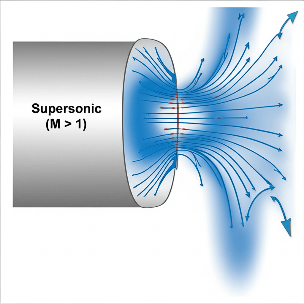
Méthodes d'amélioration de la convection : Quelles sont les techniques qui maximisent le transfert de chaleur air-surface ?
La convection est souvent le facteur limitant du refroidissement des systèmes pneumatiques. L'amélioration du transfert de chaleur par convection peut considérablement améliorer la gestion thermique et les performances du système.
Le transfert de chaleur par convection suit La loi de Newton sur le refroidissement3: Q = hA(Ts-T∞), où h est le coefficient de convection (W/m²-K), A est la surface et (Ts-T∞) est la différence de température entre la surface et le fluide. Les méthodes d'amélioration comprennent l'augmentation de la surface au moyen d'ailettes, l'amélioration de la vitesse du fluide grâce à un flux d'air dirigé et l'optimisation des caractéristiques de la surface pour favoriser les couches limites turbulentes.
Lors d'un audit d'efficacité énergétique dans une installation d'emballage en Arizona, j'ai rencontré un système pneumatique fonctionnant dans un environnement ambiant de 43°C. Les cylindres sans tige surchauffaient malgré les exigences de maintenance. Les cylindres sans tige surchauffaient bien qu'ils soient conformes à toutes les exigences de maintenance. En mettant en œuvre une amélioration ciblée de la convection - en ajoutant de petites ailettes en aluminium et un ventilateur de faible puissance - nous avons augmenté le coefficient de convection de 450%. Cela a permis de réduire les températures de fonctionnement de niveaux dangereux à des valeurs conformes aux spécifications, sans modification majeure du système.
Principes de base du transfert de chaleur par convection
L'équation de base régissant le transfert de chaleur par convection est la suivante :
Q = hA(Ts-T∞)
Où ?
- Q = Taux de transfert de chaleur (W)
- h = Coefficient de convection (W/m²-K)
- A = Surface (m²)
- Ts = Température de surface (K)
- T∞ = Température du fluide (air) (K)
Le coefficient de convection h dépend de plusieurs facteurs :
- Propriétés des fluides (densité, viscosité, conductivité thermique)
- Caractéristiques de l'écoulement (vitesse, turbulence)
- Géométrie et orientation de la surface
- Régime d'écoulement (convection naturelle ou forcée)
Convection naturelle ou forcée
| Paramètres | Convection naturelle | Convection forcée | Implications |
|---|---|---|---|
| Valeur typique h | 5-25 W/m²-K | 25-250 W/m²-K | La convection forcée peut être 10 fois plus efficace |
| Force motrice | Flottabilité (différence de température) | Pression externe (ventilateurs, soufflantes) | La convection forcée dépend moins de la température |
| Schéma d'écoulement | Ecoulement vertical le long des surfaces | Directionnel basé sur le mécanisme de forçage | Le flux forcé peut être optimisé pour des composants spécifiques |
| Fiabilité | Passive, toujours présente | Nécessite de l'énergie et de l'entretien | La convection naturelle assure un refroidissement de base |
| Exigences en matière d'espace | Nécessite un espace libre pour la circulation de l'air | Nécessite de l'espace pour les appareils de ventilation et les conduits | Les systèmes forcés doivent être mieux planifiés |
Techniques d'amélioration de la convection
Augmentation de la surface
Augmentation de la surface effective par :
Ailerons et surfaces étendues
- Ailettes à broches : Flux d'air omnidirectionnel, augmentation de la surface 150-300%
- Ailettes en plaques : Flux d'air directionnel, augmentation de la surface 200-500%
- Surfaces ondulées : Amélioration modérée, augmentation de la surface 50-150%Rugosité de la surface
- Micro-texturation : 5-15% augmentation de la surface effective
- Surfaces alvéolées : augmentation de 10-30% plus effets de la couche limite
- Les motifs rainurés : 15-40% augmentation des avantages directionnels
Manipulation des flux
Amélioration des caractéristiques de l'écoulement de l'air par :
Systèmes à air pulsé
- Ventilateurs : flux d'air directionnel, 200-600% h amélioration
- Souffleurs : Débit à haute pression, 300-800% h amélioration
- Jets d'air comprimé : Refroidissement ciblé, amélioration 400-1000% h localeOptimisation des voies d'écoulement
- Baffles : Diriger l'air vers les composants critiques
- Effets Venturi : Accélération de l'air sur des surfaces spécifiques
- Générateurs de tourbillons : Créer des turbulences pour perturber la couche limite
Modifications de la surface
Modifier les propriétés de la surface pour améliorer la convection :
Traitements d'émissivité
- Oxyde noir : Augmente l'émissivité à 0,7-0,9
- Anodisation : Émissivité contrôlée de 0,4 à 0,9
- Peintures et revêtements : Émissivité personnalisable jusqu'à 0,98Contrôle de la mouillabilité
- Revêtements hydrophiles : Améliorent le refroidissement des liquides
- Surfaces hydrophobes : Prévenir les problèmes de condensation
- Mouillabilité structurée : Flux de condensat dirigé
Exemple de mise en œuvre pratique
Pour un vérin pneumatique sans tige fonctionnant dans un environnement à haute température :
| Méthode d'amélioration | Mise en œuvre | h Amélioration | Réduction de la température |
|---|---|---|---|
| Ailerons (6mm) | Ailettes clipsables en aluminium, espacement de 10 mm | 180% | 12°C |
| Flux d'air dirigé | Ventilateur de 80 mm, 2W DC à 1,5 m/s | 320% | 18°C |
| Traitement de surface | Anodisation noire | 40% | 3°C |
| Approche combinée | Toutes les méthodes sont intégrées | 450% | 24°C |
Corrélation du nombre de Nusselt pour les calculs de conception
Pour les calculs d'ingénierie, la Nombre de Nusselt4 (Nu) fournit une approche sans dimension de la convection :
Nu = hL/k
Où ?
- L = Longueur caractéristique
- k = Conductivité thermique du fluide
Pour la convection forcée sur une plaque plane :
Nu = 0,664Re^(1/2)Pr^(1/3) (écoulement laminaire)
Nu = 0,037Re^(4/5)Pr^(1/3) (écoulement turbulent)
Où ?
- Re = Nombre de Reynolds (vitesse × longueur × densité / viscosité)
- Pr = nombre de Prandtl (chaleur spécifique × viscosité / conductivité thermique)
Ces corrélations permettent aux ingénieurs de prévoir les coefficients de convection pour différentes configurations et d'optimiser les stratégies de refroidissement en conséquence.
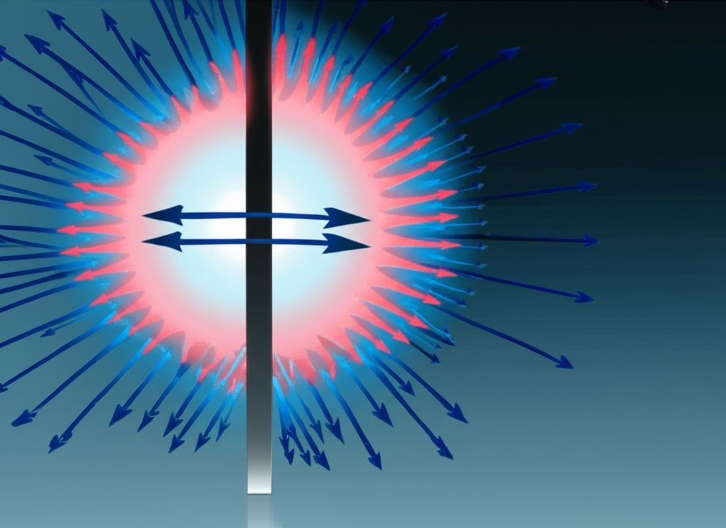
Modèle d'efficacité du rayonnement : Quand le rayonnement thermique est-il important dans les systèmes pneumatiques ?
Le rayonnement est souvent négligé dans la gestion thermique des systèmes pneumatiques, mais il peut représenter 15-30% du transfert thermique total dans de nombreuses applications. Comprendre quand et comment optimiser le transfert de chaleur par rayonnement est crucial pour une gestion thermique complète.
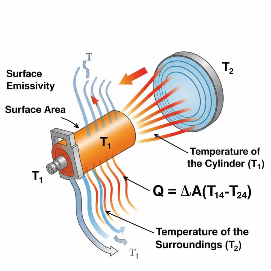
Le transfert de chaleur par rayonnement suit la Loi Stefan-Boltzmann5: Q = εσA(T₁⁴-T₂⁴), où ε est l'émissivité de la surface, σ est la constante de Stefan-Boltzmann, A est la surface, et T₁ et T₂ sont les températures absolues de la surface émettrice et de l'environnement. L'efficacité du rayonnement dans les systèmes pneumatiques dépend principalement de l'émissivité de la surface, de la différence de température et des facteurs de visibilité entre les composants et leur environnement.
J'ai récemment aidé un fabricant d'équipements semi-conducteurs de l'Oregon à résoudre des problèmes de surchauffe avec ses cylindres de précision sans tige. Leurs ingénieurs s'étaient concentrés exclusivement sur la conduction et la convection, mais avaient négligé le rayonnement. En appliquant un revêtement à haute émissivité (augmentant ε de 0,11 à 0,92), nous avons amélioré le transfert de chaleur par rayonnement de plus de 700%. Cette solution simple et passive a permis de réduire les températures de fonctionnement de 9°C sans aucune pièce mobile ni consommation d'énergie - une exigence essentielle dans leur environnement de salle blanche.
Principes du transfert de chaleur par rayonnement
L'équation de base régissant le transfert de chaleur par rayonnement est la suivante :
Q = εσA(T₁⁴-T₂⁴)
Où ?
- Q = Taux de transfert de chaleur (W)
- ε = Emissivité (sans dimension, 0-1)
- σ = constante de Stefan-Boltzmann (5,67 × 10-⁸ W/m²-K⁴)
- A = Surface (m²)
- T₁ = Température absolue de la surface (K)
- T₂ = Température absolue de l'environnement (K)
Valeurs d'émissivité de surface pour les matériaux pneumatiques courants
| Matériau/Surface | Émissivité (ε) | Efficacité du rayonnement | Potentiel d'amélioration |
|---|---|---|---|
| Aluminium poli | 0.04-0.06 | Très médiocre | >1500% amélioration possible |
| Aluminium anodisé | 0.7-0.9 | Excellent | Déjà optimisé |
| Acier inoxydable (poli) | 0.07-0.14 | Pauvre | >600% amélioration possible |
| Acier inoxydable (oxydé) | 0.6-0.85 | Bon | Amélioration modérée possible |
| Acier (poli) | 0.07-0.10 | Pauvre | >900% amélioration possible |
| Acier (oxydé) | 0.7-0.9 | Excellent | Déjà optimisé |
| Surfaces peintes | 0.8-0.98 | Excellent | Déjà optimisé |
| PTFE (blanc) | 0.8-0.9 | Excellent | Déjà optimisé |
| Caoutchouc nitrile | 0.86-0.94 | Excellent | Déjà optimisé |
Considérations sur les facteurs de visualisation
L'échange de rayonnement ne dépend pas seulement de l'émissivité, mais aussi des relations géométriques entre les surfaces :
F₁₂ = Fraction du rayonnement quittant la surface 1 et atteignant la surface 2
Pour les géométries complexes, les facteurs de vue peuvent être calculés en utilisant :
- Solutions analytiques pour les géométries simples
- Voir l'algèbre factorielle pour combiner des solutions connues
- Méthodes numériques pour les arrangements complexes
- Approximations empiriques pour l'ingénierie pratique
Dépendance du rayonnement par rapport à la température
La relation entre la puissance 4 et la température fait que le rayonnement est particulièrement efficace à des températures élevées :
| Température de surface | Pourcentage de transfert de chaleur par rayonnement* |
|---|---|
| 30°C (303K) | 5-15% |
| 50°C (323K) | 10-25% |
| 75°C (348K) | 15-35% |
| 100°C (373K) | 25-45% |
| 150°C (423K) | 35-60% |
*En supposant des conditions de convection naturelle, ε = 0,8, 25°C ambiant.
Stratégies d'amélioration de l'efficacité du rayonnement
Sur la base de mon expérience des systèmes pneumatiques industriels, voici les approches les plus efficaces pour améliorer le transfert de chaleur par rayonnement :
Modification de l'émissivité de la surface
Revêtements à haute émissivité
- Anodisation noire pour l'aluminium (ε ≈ 0.8-0.9)
- Oxyde noir pour l'acier (ε ≈ 0.7-0.8)
- Revêtements céramiques spéciaux (ε ≈ 0.9-0.98)Texture de surface
- La micro-rugosité augmente l'émissivité effective
- Les surfaces poreuses améliorent les propriétés radiatives
- Améliorations combinées de l'émissivité et de la convection
Optimisation de l'environnement
Gestion de la température ambiante
- Protection contre les équipements/processus chauds
- Refroidir les murs/plafonds pour améliorer l'échange de rayonnement
- Barrières réfléchissantes pour diriger le rayonnement vers des surfaces plus froidesVoir l'amélioration des facteurs
- Orientation pour maximiser l'exposition aux surfaces froides
- Suppression des objets bloquants
- Réflecteurs pour améliorer l'échange de rayonnement avec les zones plus froides
Étude de cas : Amélioration du rayonnement dans le domaine de la pneumatique de précision
Pour un cylindre sans tige de haute précision dans un environnement de salle blanche :
| Paramètres | Conception originale | Conception améliorée par rayonnement | Amélioration |
|---|---|---|---|
| Matériau de surface | Aluminium poli (ε ≈ 0.06) | Aluminium revêtu de céramique (ε ≈ 0.94) | 1467% augmentation de l'émissivité |
| Transfert de chaleur par rayonnement | 2.1W | 32.7W | 1457% augmentation du rayonnement |
| Température de fonctionnement | 68°C | 59°C | Réduction de 9°C |
| Durée de vie des composants | 8 mois | >24 mois | Amélioration de 3× |
| Coût de la mise en œuvre | – | $175 par cylindre | 4,2 mois de remboursement |
Rayonnement et autres modes de transfert de chaleur
Pour une gestion thermique efficace, il est essentiel de comprendre quand le rayonnement domine :
| Condition | Dominance de la conduction | Dominance de la convection | Dominance du rayonnement |
|---|---|---|---|
| Plage de température | De faible à élevé | Faible à moyen | Moyen à élevé |
| Propriétés des matériaux | Matériaux à haute teneur en k | Faible k, surface élevée | Surfaces ε élevées |
| Facteurs environnementaux | Bon contact thermique | Air en mouvement, ventilateurs | Différentiel de température important |
| Contraintes spatiales | Emballage étanche | Flux d'air ouvert | Vue sur un environnement plus frais |
| Meilleures applications | Interfaces des composants | Refroidissement général | Surfaces chaudes, vide, air calme |
Conclusion
La maîtrise des principes de transfert de chaleur - calcul du coefficient de conduction, méthodes d'amélioration de la convection et modélisation de l'efficacité du rayonnement - constitue la base d'une gestion thermique efficace dans les systèmes pneumatiques. En appliquant ces principes, vous pouvez réduire les températures de fonctionnement, prolonger la durée de vie des composants et améliorer l'efficacité énergétique tout en garantissant un fonctionnement fiable, même dans des environnements difficiles.
FAQ sur le transfert de chaleur dans les systèmes pneumatiques
Quelle est l'augmentation de température typique dans les cylindres pneumatiques en cours de fonctionnement ?
Les vérins pneumatiques subissent généralement des hausses de température de 20 à 40°C au-dessus de la température ambiante pendant leur fonctionnement continu. Cette augmentation résulte du frottement entre les joints et les parois du cylindre, du réchauffement de l'air par compression et de la conversion du travail mécanique en chaleur. Les vérins sans tige subissent souvent des hausses de température plus importantes (30-50°C) en raison de leurs systèmes d'étanchéité plus complexes et de la concentration de la chaleur dans l'ensemble palier/joint.
Comment la pression de fonctionnement affecte-t-elle la production de chaleur dans les systèmes pneumatiques ?
La pression de fonctionnement a un impact significatif sur la production de chaleur, les pressions plus élevées créant plus de chaleur par le biais de plusieurs mécanismes. Chaque augmentation de 1 bar de la pression de fonctionnement augmente généralement la production de chaleur de 8-12% en raison des forces de frottement plus importantes entre les joints et les surfaces, de l'échauffement plus important dû à la compression et de l'augmentation des pertes liées aux fuites. Cette relation est approximativement linéaire dans les plages de fonctionnement normales (3-10 bar).
Quelle est l'approche de refroidissement optimale pour les composants pneumatiques dans différents environnements ?
L'approche optimale du refroidissement varie en fonction de l'environnement : dans les environnements propres et à température modérée (15-30°C), la convection naturelle avec un espacement adéquat des composants est souvent suffisante. Dans les environnements à haute température (30-50°C), la convection forcée à l'aide de ventilateurs ou d'air comprimé devient nécessaire. Dans des conditions extrêmement chaudes (>50°C) ou lorsque la circulation de l'air est limitée, des méthodes de refroidissement actives telles que les refroidisseurs thermoélectriques ou le refroidissement par liquide peuvent être nécessaires. Dans tous les cas, l'optimisation du rayonnement par des surfaces à forte émissivité permet un refroidissement passif supplémentaire.
Comment calculer le transfert de chaleur total d'un composant pneumatique ?
Calculer le transfert de chaleur total en additionnant les contributions de chaque mécanisme : Qtotal = Qconduction + Qconvection + Qrayonnement. Pour la conduction, utilisez Q = kA(T₁-T₂)/L pour chaque chemin de chaleur. Pour la convection, on utilise Q = hA(Ts-T∞) avec les coefficients de convection appropriés. Pour le rayonnement, on utilise Q = εσA(T₁⁴-T₂⁴). Dans la plupart des applications pneumatiques industrielles fonctionnant à 30-80°C, la répartition approximative est la suivante : 20-40% pour la conduction, 40-70% pour la convection et 10-30% pour le rayonnement.
Quelle est la relation entre la température et la durée de vie des composants pneumatiques ?
La durée de vie des composants diminue de façon exponentielle avec l'augmentation de la température, suivant une relation d'Arrhenius modifiée. En règle générale, chaque augmentation de 10°C de la température de fonctionnement réduit la durée de vie des joints et des composants de 40-50%. Cela signifie qu'un composant fonctionnant à 70°C peut ne durer qu'un tiers de la durée de vie du même composant à 50°C. Cette relation est particulièrement critique pour les composants en polymère tels que les joints, les roulements et les garnitures, qui déterminent souvent l'intervalle de maintenance des systèmes pneumatiques.
-
Fournit une explication fondamentale de la loi de Fourier, le principe fondamental qui décrit comment la chaleur est conduite à travers des matériaux solides en fonction de leur conductivité thermique et du gradient de température. ↩
-
Explique la fonction et les types de matériaux d'interface thermique (MIT), qui sont utilisés pour remplir les espaces d'air microscopiques entre les composants afin d'améliorer la conduction de la chaleur et de réduire la résistance thermique. ↩
-
Détaille les principes de la loi de Newton sur le refroidissement, qui régit la manière dont les objets se refroidissent en transférant la chaleur au fluide environnant par convection, un facteur clé dans la conception des systèmes de refroidissement. ↩
-
Offre un aperçu approfondi du nombre de Nusselt, une grandeur sans dimension essentielle dans la dynamique des fluides et le transfert de chaleur qui représente le rapport entre le transfert de chaleur par convection et le transfert de chaleur par conduction à travers une frontière. ↩
-
Décrit la loi de Stefan-Boltzmann, le principe physique fondamental qui quantifie l'énergie totale rayonnée par un corps noir, ce qui est essentiel pour calculer la perte de chaleur des surfaces chaudes. ↩
