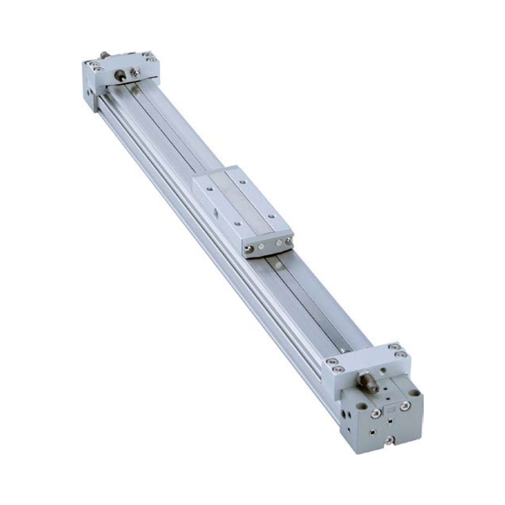
Are you puzzled by how rodless cylinders move loads without a traditional piston rod? This mystery often leads to improper selection and maintenance issues that can cost thousands in downtime. But there’s a simple way to understand these ingenious devices.
Rodless pneumatic cylinders work by transferring force through either magnetic coupling1 or mechanical joints sealed within a cylinder tube. When compressed air enters one chamber, it creates pressure that moves an internal piston, which then transfers motion to an external carriage through these coupling mechanisms, all while maintaining the pneumatic seal.
I’ve been working with these systems for over 15 years, and I’m constantly amazed by their elegant design. Let me walk you through exactly how these critical components function and what makes them so valuable in modern automation.
Table des matières
- How Does Magnetic Coupling Transfer Force in Rodless Cylinders?
- What Makes Mechanical Joint Power Transmission Effective?
- Why Do Pneumatic Seals Fail and How Can You Prevent It?
- Conclusion
- FAQs About Rodless Cylinder Operation
How Does Magnetic Coupling Transfer Force in Rodless Cylinders?
Magnetic coupling represents one of the most elegant solutions in pneumatic engineering, allowing force transfer without breaking the cylinder’s seal.
In magnetically coupled rodless cylinders, powerful permanent magnets2 are embedded in both the internal piston and external carriage. These magnets create a strong magnetic field that passes through the non-ferromagnetic cylinder wall, allowing the internal piston to “pull” the external carriage along without any physical connection.

The Physics Behind Magnetic Coupling
The magnetic coupling system relies on some fascinating principles of physics:
Magnetic Field Strength Factors
| Facteur | Effect on Coupling Strength | Implication pratique |
|---|---|---|
| Magnet Grade | Higher grades (N42, N52) provide stronger coupling | Premium cylinders use higher-grade magnets |
| Cylinder Wall Thickness | Thinner walls allow stronger coupling | Design balance between strength and magnetic efficiency |
| Magnet Configuration | Opposed pole arrays increase field strength | Modern designs use optimized magnet arrangements |
| Température de fonctionnement | Higher temperatures reduce magnetic strength | Temperature ratings affect load capacity |
I once visited a packaging facility in Germany that was experiencing intermittent carriage slippage on their magnetically coupled rodless cylinders. After inspection, we discovered they were operating at temperatures near 70°C – right at the upper limit for their magnetic system. By upgrading to our high-temperature magnetic coupling system with specially formulated magnets, we eliminated the slippage issue completely.
Dynamic Response Characteristics
The magnetic coupling system has unique dynamic properties:
- Cushioning Effect: The magnetic coupling provides natural dampening during sudden starts/stops
- Breakaway Force: The maximum force before magnetic decoupling occurs (typically 2-3× normal operating force)
- Recoupling Behavior: How the system recovers after a magnetic decoupling event
Magnetic Field Visualization
Understanding the magnetic field interaction helps visualize the working principle:
- The internal piston contains arranged permanent magnets
- The external carriage contains matching magnet arrays
- Magnetic field lines pass through the non-ferromagnetic cylinder wall
- The attraction between these magnets creates the coupling force
- As the internal piston moves, the external carriage follows
What Makes Mechanical Joint Power Transmission Effective?
While magnetic coupling offers a non-contact solution, mechanical joint systems provide the highest force transmission capabilities through physical connections.
Mechanical joint rodless cylinders use a slot along the cylinder tube with internal sealing bands. The internal piston connects directly to the external carriage through this slot via a connection bracket. This creates a positive mechanical link that can transmit higher forces than magnetic coupling while maintaining the pneumatic seal.

Sealing Band Technology
The heart of the mechanical joint system is its innovative sealing mechanism:
Sealing Band Design Evolution
| Generation | Matériau | Sealing Method | Advantages |
|---|---|---|---|
| 1st Gen | Acier inoxydable | Simple overlap | Basic sealing, moderate lifespan |
| 2nd Gen | Steel with Polymer Coating | Interlocking edges | Improved sealing, longer life |
| 3rd Gen | Composite Materials | Multi-layer design | Superior sealing, extended maintenance intervals |
| Current | Advanced Composites | Precision-engineered profile | Minimal friction, maximum lifespan, improved resistance |
Force Transmission Mechanics
The mechanical connection offers several advantages for power transmission:
Direct Force Path
The physical connection between the internal piston and external carriage creates a direct force path with:
- Zero coupling losses
- Immediate force transmission
- No decoupling under high acceleration
- Consistent performance regardless of temperature
Load Distribution Engineering
The connection bracket design is critical for proper load distribution:
- Yoke Design: Distributes forces evenly across the connection point
- Bearing Integration: Reduces friction at the interface
- Material Selection: Balances strength with weight considerations
Mechanical Joint Failure Prevention
Understanding potential failure points helps prevent issues:
Critical Stress Points
- Connection bracket attachment points
- Sealing band guide channels
- Carriage bearing interfaces
I remember consulting with a automotive parts manufacturer in Michigan who was experiencing premature wear on their mechanical joint sealing bands. After analyzing their application, we discovered they were operating with significant side-loading beyond the cylinder’s specifications. By implementing our reinforced carriage system with additional bearings, we extended their sealing band life by over 300%.
Why Do Pneumatic Seals Fail and How Can You Prevent It?
The sealing system is the most critical component in any rodless cylinder, as it maintains pressure while allowing smooth motion.
Pneumatic seals in rodless cylinders fail primarily due to contamination, improper lubrication, excessive pressure, temperature extremes, or normal wear over time. These failures manifest as air leakage, reduced force, inconsistent movement, or complete system failure.

Common Seal Failure Modes
Understanding how seals fail helps prevent costly downtime:
Primary Failure Patterns
| Failure Mode | Visual Indicators | Operational Symptoms | Prevention Measures |
|---|---|---|---|
| Abrasive Wear | Scratched seal surfaces | Gradual pressure loss | Proper air filtration, regular maintenance |
| Chemical Degradation | Discoloration, hardening | Seal deformation, leakage | Compatible lubricants, material selection |
| Extrusion Damage | Seal material pushed into gaps | Sudden pressure loss | Proper pressure regulation, anti-extrusion rings |
| Compression Set | Déformation permanente | Incomplete sealing | Temperature management, material selection |
| Installation Damage | Cuts, tears in seal | Immediate leakage | Proper installation tools, training |
Seal Material Selection Criteria
The choice of seal material dramatically affects performance:
Material Performance Comparison
| Matériau | Plage de température | Chemical Resistance | Wear Resistance | Cost Factor |
|---|---|---|---|---|
| NBR | -30°C to +100°C | Bon | Modéré | 1.0× |
| FKM (Viton)3 | -20°C to +200°C | Excellent | Bon | 2.5× |
| PTFE | -200°C to +260°C | Outstanding | Excellent | 3.0× |
| HNBR | -40°C to +165°C | Very Good | Bon | 1.8× |
| Polyurethane | -30°C to +80°C | Modéré | Excellent | 1.2× |
Advanced Seal Design Features
Modern rodless cylinders incorporate sophisticated seal designs:
Seal Profile Innovations
- Dual-Lip Configurations: Primary and secondary sealing surfaces
- Self-Adjusting Profiles: Compensate for wear over time
- Low-Friction Coatings: Reduce break-away forces and improve efficiency
- Integrated Wiper Elements: Prevent contamination ingress
Preventive Maintenance Strategies
Proper maintenance dramatically extends seal life:
Maintenance Schedule Framework
| Composant | Inspection Interval | Maintenance Action | Warning Signs |
|---|---|---|---|
| Primary Seals | 500 operating hours | Visual inspection | Pressure decay, noise |
| Wiper Seals | 250 operating hours | Cleaning, inspection | Contamination inside cylinder |
| Lubrification | 1000 operating hours | Reapplication if needed | Increased friction, jerky motion |
| Air Filtration | Weekly | Filter inspection/replacement | Moisture or particles in system |
During a recent visit to a food processing plant in Wisconsin, I encountered a production line that was replacing rodless cylinder seals every 2-3 months. After investigation, we discovered their air preparation system wasn’t removing moisture effectively. By upgrading to our advanced filtration system and switching to our food-grade compatible seal material, their maintenance interval extended to over 18 months between replacements.
Conclusion
Understanding the working principles of rodless pneumatic cylinders—whether magnetic coupling, mechanical joint, or their sealing systems—is essential for proper selection, operation, and maintenance. These innovative components continue to evolve, offering increasingly reliable and efficient solutions for linear motion applications.
FAQs About Rodless Cylinder Operation
What is the main advantage of a rodless cylinder over a traditional cylinder?
Rodless cylinders provide the same stroke length in approximately half the installation space compared to conventional cylinders. This space-saving design allows for more compact machine designs while eliminating the safety concerns of an extending rod and providing better support for side loads through the carriage bearing system.
How does a magnetically coupled rodless cylinder work?
A magnetically coupled rodless cylinder uses permanent magnets embedded in both the internal piston and external carriage. When compressed air moves the internal piston, the magnetic field passes through the non-ferromagnetic cylinder wall, pulling the external carriage along without any physical connection between the two components.
What is the maximum force a rodless cylinder can generate?
The maximum force depends on the type and size of the rodless cylinder. Mechanical joint designs typically offer the highest force capabilities, with large-bore models (100mm+) generating forces exceeding 7,000 N at 6 bar pressure. Magnetic coupling designs generally provide lower force ratings due to the limitations of magnetic field strength.
How do I prevent seal failure in rodless pneumatic cylinders?
Prevent seal failure by ensuring proper air preparation (filtration, lubrication if required), operating within specified pressure and temperature ranges, avoiding side-loading beyond rated capacities, implementing regular maintenance schedules, and using manufacturer-recommended lubricants when applicable.
Can rodless cylinders handle side loads?
Yes, rodless cylinders are designed to handle side loads, but within specific limits. Mechanical joint designs typically offer higher side load capabilities than magnetic coupling versions. The carriage bearing system supports these loads, but exceeding the manufacturer’s specifications will result in premature wear and potential failure.
What causes magnetic decoupling in rodless cylinders?
Magnetic decoupling occurs when the force required exceeds the magnetic coupling strength, typically due to excessive acceleration, overloading beyond rated capacity, extreme operating temperatures reducing magnetic field strength, or physical obstructions preventing carriage movement while the internal piston continues to move.
-
Provides a detailed explanation of the principles behind magnetic couplings, which transmit torque or force between two shafts or components without physical contact, using magnetic fields. ↩
-
Explains the different grades of permanent magnets (like N42, N52), how they are classified based on their maximum energy product, and what materials like Neodymium are used. ↩
-
Provides information on Fluoroelastomer (FKM), a high-performance synthetic rubber known by its trade name Viton®, which offers excellent resistance to heat and chemicals. ↩


