

Avez-vous déjà vu vos coûts de production monter en flèche à cause d'une panne d'équipement inattendue ? Moi, je l'ai vu. Le coupable se cache souvent dans le monde invisible des interactions de surface. Lorsque deux surfaces se rencontrent dans vos systèmes pneumatiques, la friction devient votre plus grand ennemi ou votre plus grand allié.
Tribologie1-La science du frottement, de l'usure et de la lubrification a un impact direct sur les performances des systèmes pneumatiques en affectant l'efficacité énergétique, la durée de vie des composants et la fiabilité opérationnelle. La compréhension de ces principes fondamentaux peut réduire les coûts de maintenance jusqu'à 30% et prolonger la durée de vie des équipements de plusieurs années.
Le mois dernier, j'ai visité une usine de fabrication à Boston dont les vérins sans tige tombaient en panne toutes les quelques semaines. L'équipe de maintenance est restée perplexe jusqu'à ce que nous examinions les facteurs tribologiques. À la fin de cet article, vous saurez comment appliquer les principes de la tribologie pour résoudre des problèmes similaires dans vos propres systèmes.
Table des matières
- Vérification de la friction de Coulomb : Comment tester cette loi dans des applications réelles ?
- Grades de rugosité de surface : Quelles sont les normes importantes pour les composants pneumatiques ?
- Lubrification limite : Pourquoi ce mécanisme est-il essentiel pour les systèmes pneumatiques ?
- Conclusion
- FAQ sur la tribologie dans les systèmes pneumatiques
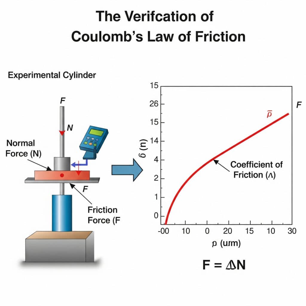
Vérification de la friction de Coulomb : Comment tester cette loi dans des applications réelles ?
La loi de Coulomb constitue le fondement de l'analyse moderne du frottement, mais comment vérifier son applicabilité dans les systèmes pneumatiques du monde réel ? Cette question a des implications significatives pour prédire le comportement des composants.
Loi de friction de Coulomb2 peut être vérifiée dans les applications pneumatiques par des essais de charge contrôlés où la force de frottement (F) est égale au coefficient de frottement (μ) multiplié par la force normale (N). Cette relation reste linéaire jusqu'à ce que la déformation du matériau ou la rupture de la lubrification se produise, ce qui la rend essentielle pour prédire les performances des vérins sans tige.
Je me souviens d'avoir travaillé avec un fabricant de pièces automobiles du Michigan qui ne comprenait pas pourquoi ses vérins guidés sans tige avaient des performances irrégulières. Nous avons mis en place un simple test de vérification de Coulomb et découvert que leur coefficient de frottement supposé était erroné de près de 40%. Cette simple constatation a transformé leur approche de la maintenance.
Méthodes de vérification pratiques
Le test de la loi de Coulomb ne nécessite pas d'équipement complexe, mais simplement une approche méthodique :
- Essais statiques: Mesure de la force nécessaire pour initier un mouvement
- Essai dynamique: Mesure de la force nécessaire pour maintenir une vitesse constante
- Essais à charge variable: Confirmation de la linéarité pour différentes forces normales
Facteurs affectant la précision du coefficient de frottement
| Facteur | Impact sur le coefficient de friction | Stratégie d'atténuation |
|---|---|---|
| Propreté de la surface | Jusqu'à la variation 200% | Protocole de nettoyage standardisé |
| Température | 5-15% variation par 10°C | Essais sous température contrôlée |
| Humidité | 3-8% variation dans les systèmes non étanches | Contrôle de l'environnement pendant les essais |
| Période de rodage | Jusqu'à 30% de réduction après la première utilisation | Préconditionner les composants avant les essais |
| Appariement des matériaux | Déterminant fondamental | Documenter les spécifications exactes des matériaux |
Idées reçues sur les essais de friction
Lors de la vérification de la loi de Coulomb dans les systèmes pneumatiques, plusieurs idées fausses peuvent conduire à des erreurs :
Hypothèse d'un coefficient de frottement constant
De nombreux ingénieurs supposent que le coefficient de frottement reste constant dans toutes les conditions. En réalité, il varie avec :
- Vélocité: Le coefficient statique diffère du coefficient dynamique
- Température: La plupart des matériaux présentent un frottement dépendant de la température
- Temps de contact: Un contact prolongé peut augmenter le frottement statique
- État de surface: L'usure modifie les caractéristiques de frottement au fil du temps
Les phénomènes d'adhérence et de glissement ne sont pas pris en compte
La transition entre le frottement statique et le frottement dynamique crée souvent un mouvement saccadé appelé coller-glisser3:
- Le composant est stationnaire (frottement statique)
- La force augmente jusqu'à ce que le mouvement commence
- La friction tombe soudainement à un niveau dynamique
- Le composant accélère
- La force diminue, le composant ralentit
- Le cycle se répète
Ce phénomène est particulièrement important pour les vérins pneumatiques sans tige fonctionnant à faible vitesse.
Grades de rugosité de surface : Quelles sont les normes importantes pour les composants pneumatiques ?
La rugosité de surface a un impact significatif sur les performances des composants pneumatiques, mais quelles sont les normes de mesure sur lesquelles vous devez vous concentrer ? La réponse varie selon l'application et le type de composant.
Les degrés de rugosité de surface pour les composants pneumatiques sont généralement compris entre Ra 0,1 à 1,6 μm4Les surfaces d'étanchéité critiques nécessitent des finitions plus lisses (0,1-0,4 μm) et les surfaces de roulement des profils de rugosité spécifiques (0,4-0,8 μm) pour retenir le lubrifiant tout en minimisant le frottement et l'usure.
Lors d'une visite de dépannage dans une usine de transformation alimentaire du Wisconsin, j'ai découvert que les défaillances de leurs vérins sans tige étaient dues à des spécifications de surface incorrectes. L'équipe de maintenance avait remplacé les joints par des composants standard, mais l'inadéquation de la rugosité de la surface a provoqué une usure accélérée. La compréhension des normes de rugosité aurait permis d'éviter cette erreur coûteuse.
Paramètres critiques de rugosité de surface
Si Ra (rugosité moyenne) est couramment spécifié, d'autres paramètres fournissent des informations cruciales :
- Rz (hauteur maximale): Différence entre le sommet le plus élevé et la vallée la plus basse
- Rsk (Skewness): Indique si le profil présente davantage de pics ou de vallées.
- Rku (Kurtosis): Décrit la netteté du profil
- Rp (hauteur maximale de la crête): Important pour le premier contact et le rodage
Exigences en matière de rugosité de surface par type de composant
| Composant | Gamme Ra recommandée (μm) | Paramètre critique | Raison |
|---|---|---|---|
| Alésage du cylindre | 0.1-0.4 | Rsk (préférence négative) | Durée de vie des joints, prévention des fuites |
| Tige de piston | 0.2-0.6 | Rz (contrôlé) | Usure des joints, rétention de la lubrification |
| Surfaces d'appui | 0.4-0.8 | Rku (platykurtique de préférence) | Rétention du lubrifiant, résistance à l'usure |
| Sièges de soupape | 0.05-0.2 | Rp (minimisé) | Efficacité de l'étanchéité, prévention des fuites |
| Surfaces externes | 0.8-1.6 | Ra (cohérent) | Résistance à la corrosion, aspect |
Méthodes de mesure et leurs applications
Les différentes techniques de mesure permettent d'obtenir des informations variées sur les caractéristiques de la surface :
Méthodes de contact
- Profilomètres à stylet: Norme pour la mesure du Ra, mais peut endommager les surfaces délicates
- Testeurs de rugosité portables: Pratique pour une utilisation sur le terrain mais moins précis
Méthodes sans contact
- Profilométrie optique: Excellent pour les matériaux souples ou les composants finis
- Balayage laser: Fournit des cartes de surface en 3D à haute résolution
- Microscopie à force atomique: Pour l'analyse à l'échelle nanométrique des surfaces critiques
Évolution de la rugosité de surface pendant la durée de vie des composants
La rugosité de la surface n'est pas statique : elle évolue tout au long du cycle de vie d'un composant :
- Étape de fabrication: Finition initiale usinée ou rectifiée
- Période de rodage: Les pics sont usés, la rugosité diminue
- Fonctionnement en régime permanent: Profil de rugosité stabilisé
- Accélération de l'usure: L'augmentation de la rugosité est le signe d'une défaillance imminente
La surveillance de ces changements peut fournir un avertissement précoce de la défaillance d'un composant, en particulier dans les applications critiques de vérins pneumatiques sans tige.
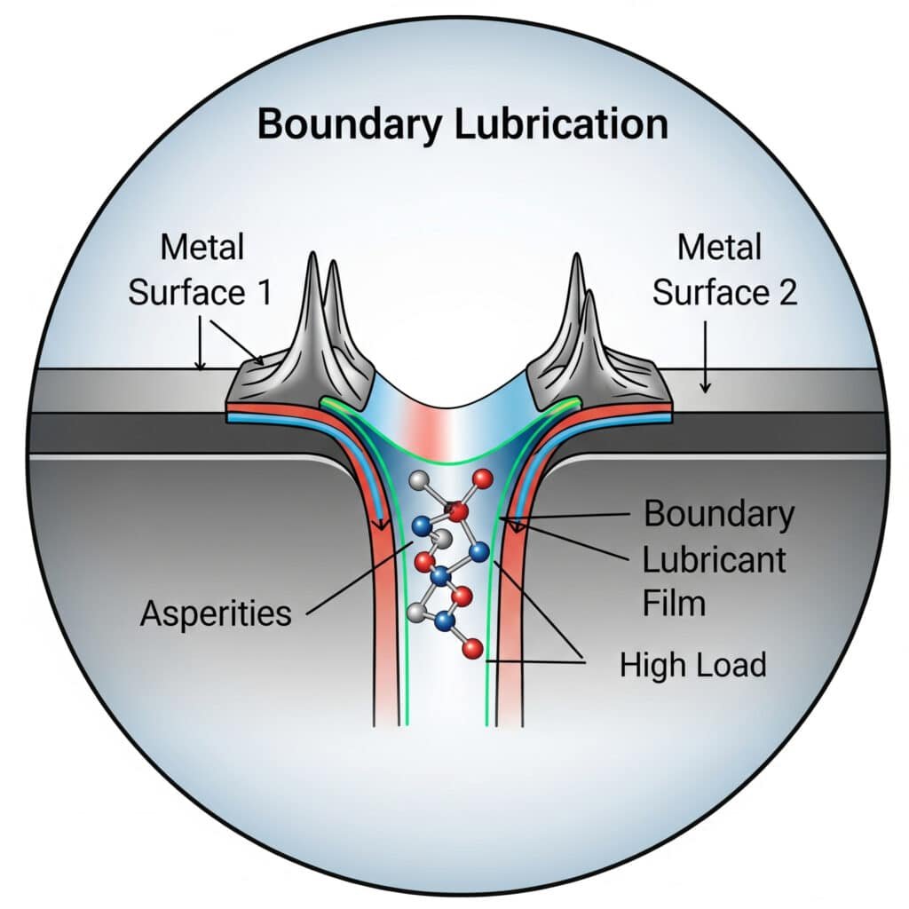
Lubrification limite : Pourquoi ce mécanisme est-il essentiel pour les systèmes pneumatiques ?
La lubrification limite représente la frontière ténue entre un fonctionnement acceptable et une défaillance catastrophique dans les systèmes pneumatiques. La compréhension de ce mécanisme est essentielle pour une maintenance et une conception adéquates.
La lubrification limite se produit lorsqu'un film de lubrifiant d'une finesse moléculaire sépare deux surfaces dans des conditions de charge élevée ou de faible vitesse. Ce régime est essentiel dans les systèmes pneumatiques car il protège les composants pendant le démarrage, le fonctionnement à faible vitesse et les scénarios de charge élevée lorsque la lubrification complète du film de fluide ne peut pas être maintenue.
J'ai récemment consulté un fabricant californien d'équipements d'emballage dont les vérins magnétiques sans tige présentaient une défaillance prématurée des joints. Ses ingénieurs avaient choisi un lubrifiant en se basant uniquement sur la viscosité, sans tenir compte des propriétés de lubrification périphérique. Après avoir opté pour un lubrifiant contenant des additifs de qualité supérieure, la durée de vie des joints a été multipliée par trois.
Les quatre régimes de lubrification
Pour comprendre l'importance de la lubrification limite, il faut la replacer dans son contexte :
- Lubrification limite: Aspérités de surface en contact direct, protégées uniquement par des films moléculaires
- Lubrification mixte: Film fluide partiel avec contact avec les aspérités
- Lubrification élastohydrodynamique: Film fluide mince avec déformation de la surface
- Lubrification hydrodynamique: Séparation complète par film fluide
Mécanismes de lubrification limite
Comment la lubrification limite protège-t-elle les surfaces ? Plusieurs mécanismes sont à l'œuvre :
Adsorption
Les molécules polaires du lubrifiant s'attachent aux surfaces métalliques, créant ainsi des couches protectrices :
- La "tête" polaire se lie à la surface du métal
- La "queue" non polaire s'étend vers l'extérieur
- Ces molécules alignées résistent à la pénétration
- Plusieurs couches peuvent se former pour une meilleure protection
Réaction chimique
Certains additifs réagissent avec les surfaces pour former des composés protecteurs :
- ZDDP (Dialkyldithiophosphate de zinc)[^5]: Forme un verre phosphaté protecteur
- Composés du soufre: Créer des couches protectrices de sulfure de fer
- Acides gras: Réagissent pour former des savons métalliques sur les surfaces
Sélection des lubrifiants pour les conditions limites
Pour les composants pneumatiques tels que les vérins sans tige qui fonctionnent fréquemment dans des conditions limites :
| Type d'additif | Fonction | Meilleure application |
|---|---|---|
| Anti-usure (AW) | Forme des films protecteurs sous des charges modérées | Composants pneumatiques généraux |
| Pression extrême (EP) | Création de couches superficielles sacrificielles sous des charges élevées | Applications lourdes |
| Modificateurs de friction | Réduit le glissement dans les conditions limites | Systèmes de positionnement de précision |
| Lubrifiants solides (PTFE, Graphite) | Assure la séparation physique en cas de défaillance du film fluide | Applications à charge élevée et à faible vitesse |
Optimisation de la lubrification des frontières dans les systèmes pneumatiques
Maximiser la durée de vie des composants grâce à une meilleure lubrification limite :
- Préparation de la surface: La rugosité contrôlée crée des réservoirs de lubrifiant
- Sélection des additifs: Adapter les additifs aux paires de matériaux et aux conditions d'utilisation
- Intervalles de relubrification: Plus fréquente que dans le cas d'une lubrification à film complet
- Contrôle de la contamination: Les particules perturbent les films limites plus gravement que les films fluides
- Gestion de la température: Les additifs limites ont une efficacité qui dépend de la température.
Conclusion
La compréhension des principes fondamentaux de la tribologie - vérification du frottement de Coulomb, normes de rugosité de surface et mécanismes de lubrification limite - est essentielle à l'optimisation des performances des systèmes pneumatiques. En appliquant ces principes, vous pouvez réduire de manière significative les coûts de maintenance, prolonger la durée de vie des composants et améliorer la fiabilité opérationnelle.
FAQ sur la tribologie dans les systèmes pneumatiques
Qu'est-ce que la tribologie et pourquoi est-elle importante pour les systèmes pneumatiques ?
La tribologie est la science des surfaces en interaction et en mouvement relatif, y compris le frottement, l'usure et la lubrification. Dans les systèmes pneumatiques, les facteurs tribologiques ont un impact direct sur l'efficacité énergétique, la durée de vie des composants et la fiabilité opérationnelle. Une bonne gestion tribologique peut réduire la consommation d'énergie de 10-15% et prolonger la durée de vie des composants de 2 à 3 fois.
Comment la rugosité de la surface affecte-t-elle la durée de vie des joints dans les cylindres sans tige ?
La rugosité de surface affecte la durée de vie des joints par de multiples mécanismes : une surface trop lisse offre une rétention insuffisante du lubrifiant, tandis qu'une surface trop rugueuse provoque une usure accélérée des joints. Une rugosité de surface optimale (généralement Ra 0,1-0,4 μm) crée des vallées microscopiques qui agissent comme des réservoirs de lubrifiant tout en conservant un profil suffisamment lisse pour éviter d'endommager les joints.
Quelle est la différence entre la lubrification limite et la lubrification hydrodynamique ?
La lubrification limite se produit lorsque les surfaces ne sont séparées que par des films moléculaires minces d'additifs lubrifiants, avec un certain contact entre les aspérités. La lubrification hydrodynamique se caractérise par une séparation complète des surfaces par un film de fluide. Les composants pneumatiques fonctionnent généralement en régime de lubrification limite ou mixte pendant le démarrage et le fonctionnement à faible vitesse.
Comment puis-je vérifier si la loi de frottement de Coulomb s'applique à mon application spécifique ?
Effectuez un test simple en mesurant la force de frottement à différentes charges normales tout en maintenant une vitesse et une température constantes. Tracez les résultats - si la relation est linéaire (force de frottement = coefficient de frottement × force normale), la loi de Coulomb s'applique. Les écarts par rapport à la linéarité indiquent que d'autres facteurs, tels que l'adhérence ou la déformation du matériau, sont significatifs.
Quelles sont les propriétés des lubrifiants les plus importantes pour les composants pneumatiques ?
Pour les composants pneumatiques, en particulier les vérins sans tige, les principales propriétés des lubrifiants sont les suivantes : viscosité adaptée à la plage de températures de fonctionnement, additifs de lubrification limite puissants, compatibilité avec les matériaux d'étanchéité, résistance à l'eau et à l'oxydation, et bonne adhérence aux surfaces métalliques. Les lubrifiants synthétiques sont souvent plus performants que les huiles minérales dans ces applications.
-
Fournit une vue d'ensemble de la tribologie, science interdisciplinaire qui étudie le frottement, l'usure, la lubrification et la conception de surfaces en interaction et en mouvement relatif. ↩
-
Offre une explication détaillée des lois de Coulomb sur le frottement sec, qui sont des modèles fondamentaux utilisés pour approximer les forces de frottement statique et cinétique. ↩
-
Explique la dynamique du frottement stick-slip, un mouvement saccadé spontané qui peut se produire lorsque deux objets glissent l'un sur l'autre, ce qui est essentiel pour comprendre les instabilités à faible vitesse. ↩
-
Fournit une définition technique de Ra, la moyenne arithmétique des valeurs absolues des écarts de hauteur de profil par rapport à la ligne moyenne, qui est le paramètre le plus utilisé pour la finition de surface. ↩
