

Heb je ooit gezien hoe je productiekosten de pan uit rezen door onverwachte apparatuurstoringen? Ik wel. De boosdoener schuilt vaak in de onzichtbare wereld van oppervlakte-interacties. Wanneer twee oppervlakken elkaar ontmoeten in uw pneumatische systemen, wordt wrijving uw grootste vijand of uw grootste bondgenoot.
Tribologie1de wetenschap van wrijving, slijtage en smering - heeft een directe invloed op de prestaties van pneumatische systemen door de energie-efficiëntie, de levensduur van componenten en de bedrijfszekerheid te beïnvloeden. Inzicht in deze fundamentele principes kan de onderhoudskosten tot 30% verlagen en de levensduur van apparatuur met jaren verlengen.
Vorige maand bezocht ik een fabriek in Boston waar hun cilinders zonder stang het om de paar weken begaven. Het onderhoudsteam stond voor een raadsel totdat we de tribologische factoren onderzochten. Aan het eind van dit artikel zult u begrijpen hoe u tribologische grondbeginselen kunt toepassen om soortgelijke problemen in uw eigen systemen op te lossen.
Inhoudsopgave
- Coulomb-wrijving verifiëren: Hoe kun je deze wet testen in echte toepassingen?
- Ruwheidsgraden van oppervlakken: Welke normen zijn van belang voor pneumatische componenten?
- Grenssmering: Waarom is dit mechanisme cruciaal voor pneumatische systemen?
- Conclusie
- Veelgestelde vragen over tribologie in pneumatische systemen
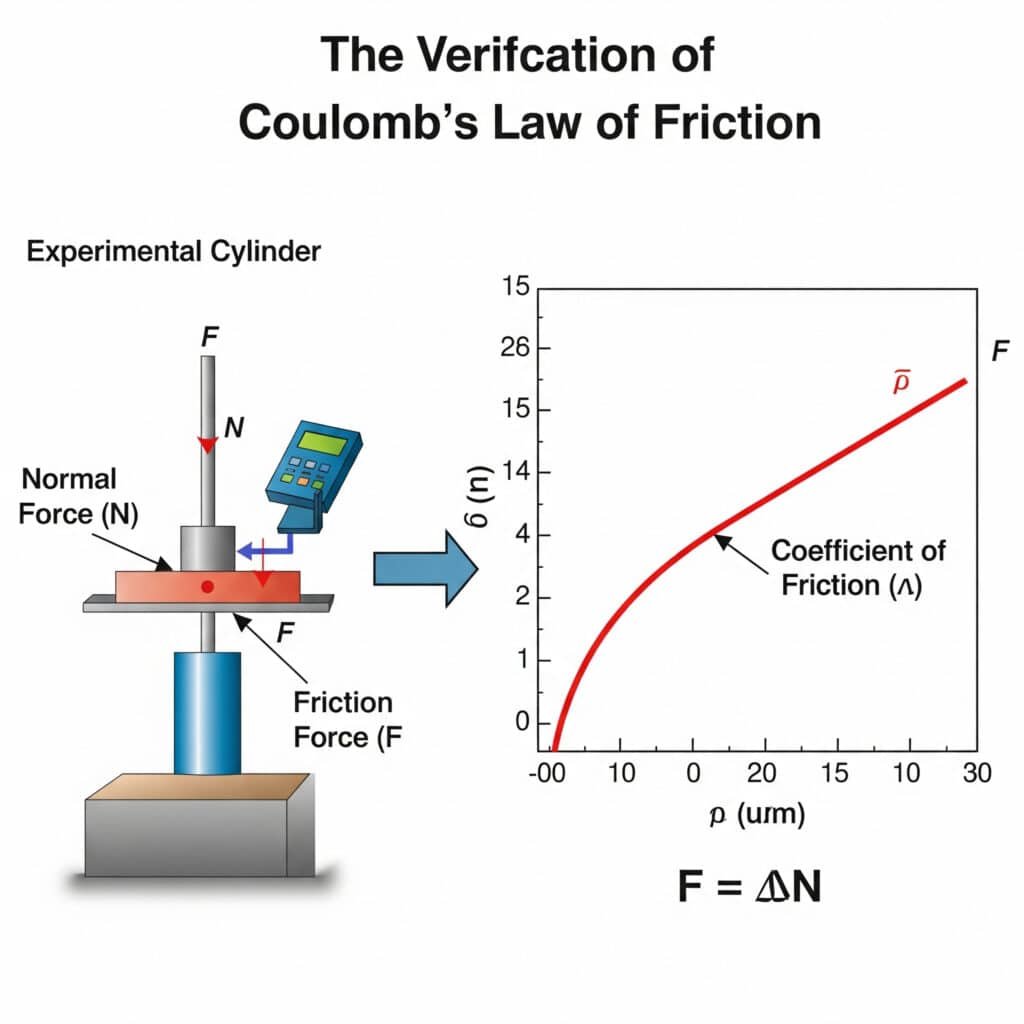
Coulomb-wrijving verifiëren: Hoe kun je deze wet testen in echte toepassingen?
De basis van moderne wrijvingsanalyse begint met de Wet van Coulomb, maar hoe controleren we de toepasbaarheid in echte pneumatische systemen? Deze vraag heeft belangrijke implicaties voor het voorspellen van het gedrag van componenten.
De wrijvingswet van Coulomb2 kan worden geverifieerd in pneumatische toepassingen door middel van gecontroleerde belastingstests waarbij de wrijvingskracht (F) gelijk is aan de wrijvingscoëfficiënt (μ) vermenigvuldigd met de normaalkracht (N). Deze relatie blijft lineair totdat materiaalvervorming of smeringsafbraak optreedt, waardoor ze essentieel is voor het voorspellen van de prestaties van cilinders zonder stang.
Ik herinner me dat ik samenwerkte met een fabrikant van auto-onderdelen in Michigan die niet begreep waarom hun geleide cilinders zonder stang inconsistent presteerden. We voerden een eenvoudige Coulomb-verificatietest uit en ontdekten dat hun veronderstelde wrijvingscoëfficiënt er bijna 40% naast zat. Dit inzicht veranderde hun onderhoudsaanpak.
Praktische verificatiemethoden
Om de Wet van Coulomb te testen is geen ingewikkelde apparatuur nodig, alleen een methodische aanpak:
- Statisch testen: De kracht meten die nodig is om een beweging in gang te zetten
- Dynamisch testen: De kracht meten die nodig is om een constante snelheid te behouden
- Testen met variabele belasting: Bevestiging van lineariteit bij verschillende normaalkrachten
Factoren die de nauwkeurigheid van de wrijvingscoëfficiënt beïnvloeden
| Factor | Invloed op wrijvingscoëfficiënt | Matigingsstrategie |
|---|---|---|
| Reinheid van het oppervlak | Variatie tot 200% | Gestandaardiseerd reinigingsprotocol |
| Temperatuur | 5-15% verandering per 10°C | Temperatuurgecontroleerd testen |
| Vochtigheid | 3-8% variatie in niet-afgedichte systemen | Omgevingscontrole tijdens het testen |
| Inloopperiode | Tot 30% reductie na eerste gebruik | Componenten voorbehandelen voor het testen |
| Materiaal koppelen | Fundamentele determinant | Exacte materiaalspecificaties documenteren |
Veelvoorkomende misvattingen bij wrijvingstesten
Bij het verifiëren van de Wet van Coulomb in pneumatische systemen kunnen verschillende misvattingen tot fouten leiden:
Veronderstelling van constante wrijvingscoëfficiënt
Veel ingenieurs gaan ervan uit dat de wrijvingscoëfficiënt constant blijft onder alle omstandigheden. In werkelijkheid varieert deze met:
- Snelheid: Statische coëfficiënt verschilt van dynamische coëfficiënt
- Temperatuur: De meeste materialen vertonen temperatuurafhankelijke wrijving
- Contacttijd: Langdurig contact kan de statische wrijving verhogen
- Oppervlaktegesteldheid: Slijtage verandert de wrijvingskarakteristieken na verloop van tijd
Stick-Slip-fenomenen over het hoofd zien
De overgang tussen statische en dynamische wrijving zorgt vaak voor een schokkerige beweging die stick-slip3:
- Onderdeel is stationair (statische wrijving is van toepassing)
- Kracht neemt toe tot beweging begint
- Wrijving daalt plotseling naar dynamisch niveau
- Component versnelt
- Kracht neemt af, component vertraagt
- Cyclusherhalingen
Dit fenomeen is vooral relevant voor pneumatische cilinders zonder stangen die werken bij lage snelheden.
Ruwheidsgraden van oppervlakken: Welke normen zijn van belang voor pneumatische componenten?
Oppervlakteruwheid heeft een grote invloed op de prestaties van pneumatische componenten, maar op welke meetstandaarden moet u zich richten? Het antwoord varieert per toepassing en type component.
Oppervlakteruwheidsklassen voor pneumatische onderdelen variëren meestal van Ra 0,1 tot 1,6 μm4Met kritische afdichtingsoppervlakken die een gladdere afwerking vereisen (0,1-0,4 μm) en lageroppervlakken die specifieke ruwheidsprofielen nodig hebben (0,4-0,8 μm) om smeermiddel vast te houden en wrijving en slijtage te minimaliseren.
Tijdens een probleemoplossingsbezoek aan een voedselverwerkingsbedrijf in Wisconsin ontdekte ik dat de storingen aan hun stangloze cilinders te wijten waren aan onjuiste oppervlaktespecificaties. Hun onderhoudsteam had afdichtingen vervangen door standaardcomponenten, maar de onjuiste oppervlakteruwheid veroorzaakte versnelde slijtage. Inzicht in de ruwheidsnormen had deze kostbare fout kunnen voorkomen.
Kritische oppervlakteruwheidsparameters
Terwijl Ra (gemiddelde ruwheid) vaak wordt gespecificeerd, geven andere parameters cruciale informatie:
- Rz (maximale hoogte): Het verschil tussen de hoogste piek en het laagste dal
- Rsk (scheefheid): Geeft aan of het profiel meer pieken of dalen heeft
- Rku (kurtosis): Beschrijft de scherpte van het profiel
- Rp (maximale piekhoogte): Belangrijk voor het eerste contact en het inlopen
Vereisten voor oppervlakteruwheid per onderdeeltype
| Component | Aanbevolen Ra-bereik (μm) | Kritische parameter | Reden |
|---|---|---|---|
| Cilinderboring | 0.1-0.4 | Rsk (negatieve voorkeur) | Levensduur afdichting, lekkagepreventie |
| Zuigerstang | 0.2-0.6 | Rz (gecontroleerd) | Afdichtingsslijtage, smeringsbehoud |
| Lageroppervlakken | 0.4-0.8 | Rku (platykurtische voorkeur) | Behoud van smeermiddel, slijtvastheid |
| Klepzittingen | 0.05-0.2 | Rp (geminimaliseerd) | Afdichtingsefficiëntie, lekkagepreventie |
| Externe oppervlakken | 0.8-1.6 | Ra (consistent) | Corrosiebestendigheid, uiterlijk |
Meetmethoden en hun toepassingen
Verschillende meettechnieken geven verschillende inzichten in oppervlaktekenmerken:
Contactmethoden
- Stylus profielmeters: Standaard voor Ra-meting, maar kan kwetsbare oppervlakken beschadigen
- Draagbare ruwheidstesters: Handig voor gebruik in het veld, maar minder nauwkeurig
Contactloze methoden
- Optische profielmeting: Uitstekend voor zachte materialen of afgewerkte onderdelen
- Laserscannen: Biedt 3D-oppervlaktekaarten met hoge resolutie
- Atoomkrachtmicroscopie: Voor analyse op nanoschaal van kritische oppervlakken
Ontwikkeling van de oppervlakteruwheid tijdens de levensduur van componenten
Oppervlakteruwheid is niet statisch, maar evolueert gedurende de levenscyclus van een onderdeel:
- Productiefase: Eerste machinale of geslepen afwerking
- Inloopperiode: Pieken worden afgesleten, ruwheid neemt af
- Werking in stabiele toestand: Gestabiliseerd ruwheidsprofiel
- Slijtageversnelling: Toenemende ruwheid duidt op naderend falen
Het monitoren van deze veranderingen kan vroegtijdig waarschuwen voor defecten aan onderdelen, vooral in kritieke toepassingen met pneumatische cilinders zonder staaf.
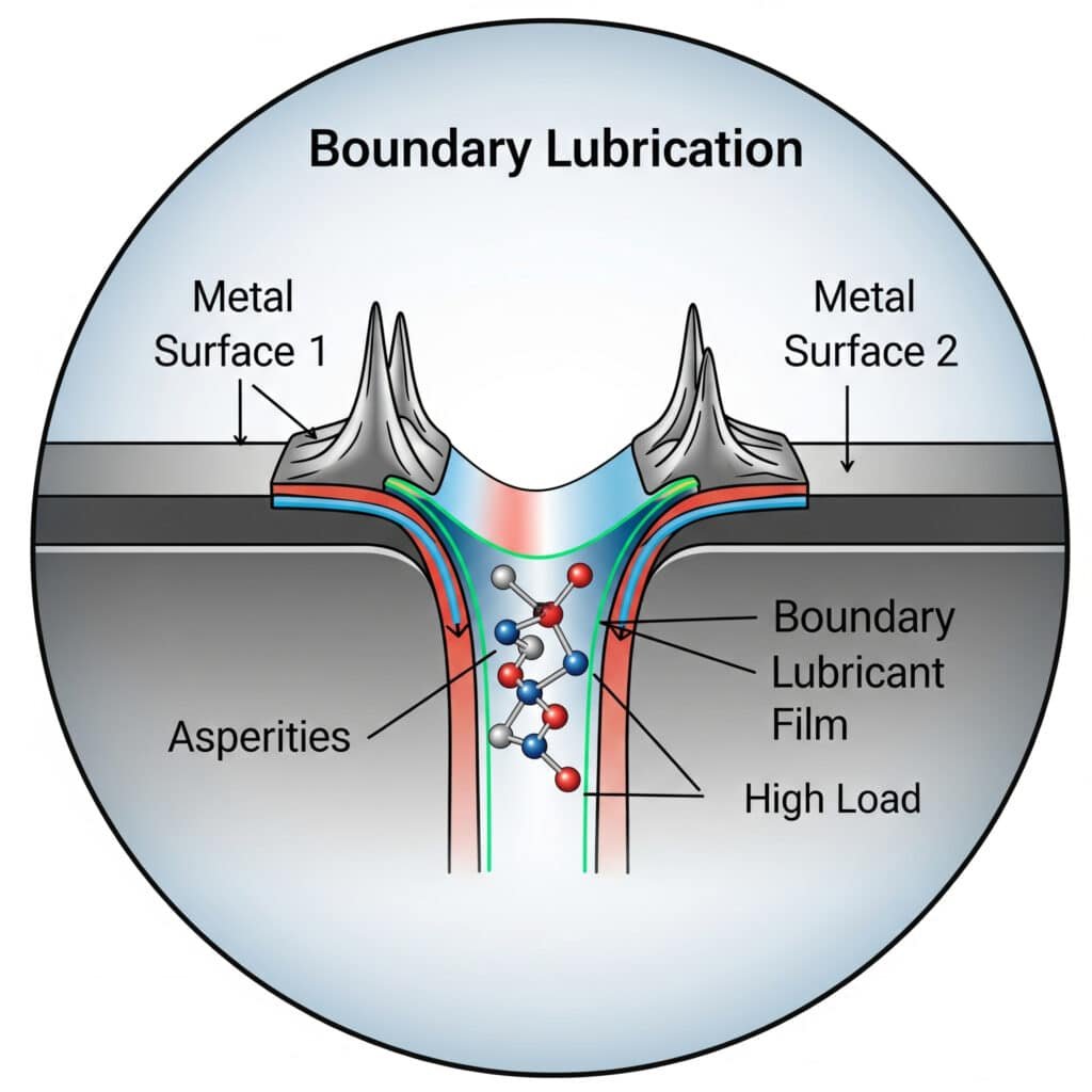
Grenssmering: Waarom is dit mechanisme cruciaal voor pneumatische systemen?
Grenssmering vormt de dunne lijn tussen acceptabele werking en catastrofale uitval in pneumatische systemen. Inzicht in dit mechanisme is essentieel voor goed onderhoud en ontwerp.
Grenssmering treedt op wanneer een moleculair dunne smeermiddelfilm twee oppervlakken scheidt bij hoge belasting of lage snelheid. Dit regime is kritisch in pneumatische systemen omdat het onderdelen beschermt tijdens het opstarten, werking bij lage snelheid en scenario's met hoge belasting wanneer de smering van de volledige vloeistoffilm niet kan worden gehandhaafd.
Onlangs heb ik overlegd met een fabrikant van verpakkingsmachines in Californië, wiens magnetische cilinders zonder staaf het voortijdig begaven. Hun technici hadden een smeermiddel gekozen dat alleen op viscositeit was gebaseerd, zonder rekening te houden met de grenssmeringseigenschappen. Nadat ze waren overgestapt op een smeermiddel met superieure grenssmeringseigenschappen, nam de levensduur van de afdichting drie keer zo snel toe.
De vier smeerregimes
Om het belang van grenssmering te begrijpen, moeten we het in de juiste context plaatsen:
- Grenssmering: Oppervlakte-asperiteiten in direct contact, alleen beschermd door moleculaire films
- Gemengde smering: Gedeeltelijke vloeistoffilm met enig asperiteitscontact
- Elastohydrodynamische smering: Dunne vloeistoffilm met oppervlaktevervorming
- Hydrodynamische smering: Volledige scheiding door vloeistoffilm
Mechanismen voor grenssmering
Hoe beschermt grenssmering precies oppervlakken? Verschillende mechanismen werken samen:
Adsorptie
Polaire moleculen in het smeermiddel hechten zich aan metalen oppervlakken en vormen beschermende lagen:
- De polaire "kop" hecht zich aan het metaaloppervlak
- De niet-polaire "staart" strekt zich naar buiten uit
- Deze uitgelijnde moleculen weerstaan penetratie
- Er kunnen meerdere lagen worden gevormd voor een betere bescherming
Chemische reactie
Sommige additieven reageren met oppervlakken om beschermende verbindingen te vormen:
- ZDDP (zinkdialkyldithiofosfaat)[^5]: Vormt beschermend fosfaatglas
- Zwavelverbindingen: IJzersulfide beschermende lagen creëren
- Vetzuren: Reageren om metaalzeep te vormen op oppervlakken
Smeermiddelen selecteren voor randvoorwaarden
Voor pneumatische onderdelen zoals cilinders zonder stang die vaak onder grensomstandigheden werken:
| Type toevoeging | Functie | Beste toepassing |
|---|---|---|
| Slijtageweerstand (AW) | Vormt beschermende lagen onder matige belasting | Algemene pneumatische onderdelen |
| Extreme druk (EP) | Creëert opofferende oppervlaktelagen onder hoge belastingen | Zware toepassingen |
| Wrijvingswijzigers | Vermindert stick-slip in randvoorwaarden | Precisiepositioneersystemen |
| Vaste smeermiddelen (PTFE, grafiet) | Biedt fysieke scheiding wanneer de vloeistoffilm het laat afweten | Toepassingen met hoge belasting en lage snelheid |
Optimaliseren van grenssmering in pneumatische systemen
De levensduur van onderdelen maximaliseren door verbeterde grenssmering:
- Oppervlaktevoorbereiding: Gecontroleerde ruwheid creëert smeermiddelreservoirs
- Additief selecteren: Additieven afstemmen op materiaalparen en bedrijfsomstandigheden
- Nasmeerintervallen: Vaker dan bij volledige smering
- Controle op vervuiling: Deeltjes verstoren grenslagen sterker dan vloeistoffilms
- Temperatuurbeheer: Grensadditieven hebben temperatuurafhankelijke effectiviteit
Conclusie
Inzicht in de grondbeginselen van tribologie - verificatie vanoulombwrijving, normen voor oppervlakteruwheid en grenssmeringsmechanismen - is essentieel voor het optimaliseren van de prestaties van pneumatische systemen. Door deze principes toe te passen, kunt u de onderhoudskosten aanzienlijk verlagen, de levensduur van componenten verlengen en de bedrijfszekerheid verbeteren.
Veelgestelde vragen over tribologie in pneumatische systemen
Wat is tribologie en waarom is het belangrijk voor pneumatische systemen?
Tribologie is de wetenschap van op elkaar inwerkende oppervlakken in relatieve beweging, inclusief wrijving, slijtage en smering. In pneumatische systemen hebben tribologische factoren een directe invloed op de energie-efficiëntie, de levensduur van componenten en de bedrijfszekerheid. Goed tribologisch beheer kan het energieverbruik met 10-15% verminderen en de levensduur van componenten met 2-3 keer verlengen.
Hoe beïnvloedt oppervlakteruwheid de levensduur van afdichtingen in cilinders zonder stang?
Oppervlakteruwheid beïnvloedt de levensduur van afdichtingen via meerdere mechanismen: een te glad oppervlak houdt onvoldoende smeermiddel vast, terwijl een te ruw oppervlak versnelde slijtage van de afdichting veroorzaakt. Een optimale oppervlakteruwheid (meestal Ra 0,1-0,4 μm) creëert microscopische valleien die fungeren als smeermiddelreservoirs terwijl het profiel glad genoeg blijft om schade aan de afdichting te voorkomen.
Wat is het verschil tussen grenssmering en hydrodynamische smering?
Grenssmering treedt op wanneer oppervlakken alleen worden gescheiden door moleculair dunne films van smeermiddeladditieven, waarbij nog enig asperiteitscontact optreedt. Hydrodynamische smering kenmerkt zich door volledige scheiding van oppervlakken door een vloeistoffilm. Pneumatische componenten werken meestal in grenssmering of gemengde smering tijdens het opstarten en bedrijf bij lage snelheden.
Hoe kan ik controleren of de wrijvingswet van Coulomb van toepassing is op mijn specifieke toepassing?
Voer een eenvoudige test uit door de wrijvingskracht te meten bij verschillende normaalbelastingen terwijl de snelheid en temperatuur constant blijven. Zet de resultaten uit - als de relatie lineair is (wrijvingskracht = wrijvingscoëfficiënt × normaalkracht), geldt de wet van Coulomb. Afwijkingen van lineariteit geven aan dat andere factoren zoals adhesie of materiaalvervorming van belang zijn.
Welke eigenschappen van smeermiddelen zijn het belangrijkst voor pneumatische onderdelen?
Voor pneumatische onderdelen, met name cilinders zonder stangen, zijn de belangrijkste eigenschappen van smeermiddelen: de juiste viscositeit voor het bedrijfstemperatuurbereik, sterke additieven voor grenssmering, compatibiliteit met afdichtingsmaterialen, water- en oxidatiebestendigheid en goede hechting aan metalen oppervlakken. Synthetische smeermiddelen presteren in deze toepassingen vaak beter dan minerale oliën.
-
Biedt een uitgebreid overzicht van tribologie, de interdisciplinaire wetenschap die wrijving, slijtage, smering en het ontwerp van op elkaar inwerkende oppervlakken in relatieve beweging bestudeert. ↩
-
Biedt een gedetailleerde uitleg van de wetten van Coulomb over droge wrijving. Dit zijn fundamentele modellen die worden gebruikt om de krachten van statische en kinetische wrijving te benaderen. ↩
-
Verklaart de dynamica van stick-slipwrijving, een spontane schokkerige beweging die kan optreden als twee voorwerpen over elkaar glijden, wat cruciaal is voor het begrijpen van instabiliteiten bij lage snelheden. ↩
-
Geeft een technische definitie van Ra, het rekenkundig gemiddelde van de absolute waarden van de afwijkingen van de profielhoogte ten opzichte van de gemiddelde lijn, de meest gebruikte parameter voor oppervlakteafwerking. ↩
