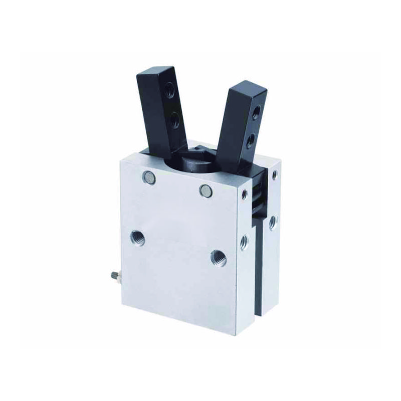
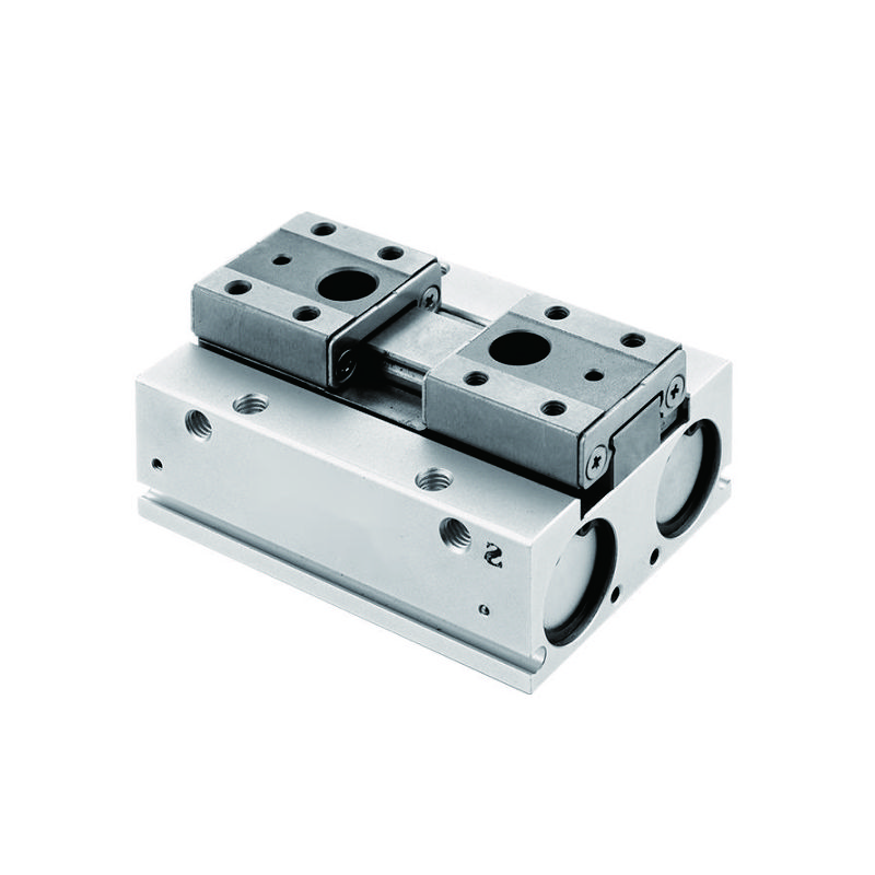
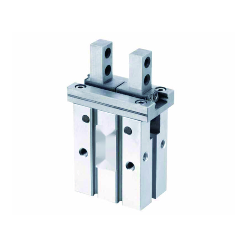
Every week, I receive calls from automation engineers struggling with end-of-arm tooling1 that’s too bulky, too slow, or simply unreliable in high-precision applications. The challenge becomes even more critical when payload capacity and cycle time requirements push conventional cylinder designs beyond their practical limits. 🤖
Compact cylinders in end-of-arm tooling require careful consideration of weight-to-force ratios, mounting configurations, and integration with robotic control systems to achieve optimal gripping performance while maintaining cycle speeds above 60 operations per minute.
Last month, I worked with David, a robotics engineer at an automotive parts facility in Michigan, whose pick-and-place system was failing to meet production targets due to oversized pneumatic components that created excessive inertia and reduced positioning accuracy.
Table of Contents
- What Are the Key Size Constraints for End-of-Arm Cylinder Applications?
- How Do You Calculate Force Requirements for Gripping Applications?
- Which Mounting Methods Optimize Space Utilization in Compact Designs?
- What Integration Challenges Must You Address with Robotic Control Systems?
What Are the Key Size Constraints for End-of-Arm Cylinder Applications?
End-of-arm tooling operates within strict dimensional limits that directly impact robot performance and payload capacity.
Critical size constraints include maximum weight limits of 2-5kg for typical industrial robots, envelope restrictions within 200mm x 200mm footprints, and center-of-gravity2 considerations that affect robot accuracy and cycle time performance.
Weight Distribution Analysis
The fundamental challenge in end-of-arm design is balancing gripping force with overall system weight. Here’s what I’ve learned from hundreds of installations:
| Robot Payload | Max Tooling Weight | Compact Cylinder Bore | Force Output |
|---|---|---|---|
| 5kg | 1.5kg | 16mm | 120N @ 6 bar |
| 10kg | 3.0kg | 20mm | 190N @ 6 bar |
| 25kg | 7.5kg | 32mm | 480N @ 6 bar |
| 50kg | 15kg | 40mm | 750N @ 6 bar |
Envelope Optimization Strategies
Space efficiency becomes critical when multiple cylinders are required for complex gripping patterns. I always recommend these design principles:
- Nested mounting to minimize overall footprint
- Integrated manifolds to reduce connection complexity
- Compact valve integration within the cylinder body
- Flexible mounting orientations for optimal space utilization
Center of Gravity Considerations
Sarah, a design engineer from a packaging equipment company in North Carolina, discovered that moving her cylinder mounting point just 25mm closer to the robot wrist improved positioning accuracy by 40% and increased cycle speed by 15%. The lesson: every millimeter matters in end-of-arm applications. 📏
How Do You Calculate Force Requirements for Gripping Applications?
Proper force calculation ensures reliable part handling while preventing damage to delicate components or workpieces.
Gripping force calculations must account for part weight, acceleration forces during robot motion, safety factors of 2-3x for critical applications, and friction coefficients3 between gripper surfaces and workpiece materials.
Force Calculation Formula
The basic formula I use for end-of-arm gripping applications is:
F_required = (W + F_acceleration) × SF / μ
Where:
- W = Part weight (N)
- F_acceleration = ma (mass × acceleration)
- SF = Safety factor (2-3x)
- μ = Friction coefficient
Material-Specific Friction Coefficients
| Material Combination | Friction Coefficient | Recommended Safety Factor |
|---|---|---|
| Steel on rubber | 0.7-0.9 | 2.0x |
| Aluminum on urethane | 0.8-1.2 | 2.5x |
| Plastic on textured grip | 0.4-0.6 | 3.0x |
| Glass/ceramic | 0.2-0.4 | 3.5x |
Dynamic Force Analysis
High-speed robotic applications generate significant acceleration forces that must be considered in cylinder sizing. For a 1kg part moving at 2 m/s² acceleration:
Static force: 10N (part weight)
Dynamic force: 2N (acceleration)
Total with 2.5x safety factor: 30N minimum gripping force
At Bepto, our compact cylinders are specifically designed for these demanding applications, offering superior force-to-weight ratios compared to traditional designs. 💪
Which Mounting Methods Optimize Space Utilization in Compact Designs?
Strategic mounting approaches can reduce overall tooling size by 30-50% while improving accessibility for maintenance and adjustment.
Optimal mounting methods include integrated manifolds4 systems, multi-axis mounting brackets, through-hole designs for nested installations, and modular connection systems that eliminate external plumbing and reduce assembly complexity.
Mounting Configuration Comparison
Traditional vs. Compact Mounting
| Mounting Type | Space Efficiency | Maintenance Access | Cost Impact |
|---|---|---|---|
| External manifold | 60% | Good | Standard |
| Integrated manifold | 85% | Limited | +15% |
| Through-hole design | 90% | Excellent | +25% |
| Modular system | 95% | Outstanding | +30% |
Bepto Compact Cylinder Advantages
Our Bepto compact cylinders feature innovative mounting solutions that outperform traditional designs:
| Feature | Standard Design | Bepto Compact | Space Savings |
|---|---|---|---|
| Overall Length | 180mm | 125mm | 30% |
| Mounting Hardware | External | Integrated | 40% |
| Air Connections | Side-mounted | Through-body | 25% |
| Total System Weight | 850g | 590g | 31% |
Modular Integration Benefits
Michael, a systems integrator from a medical device company in California, reduced his end-of-arm tooling assembly time from 4 hours to 90 minutes by switching to our modular compact cylinder system. The integrated connections eliminated 12 separate fittings and reduced potential leak points by 75%. 🔧
What Integration Challenges Must You Address with Robotic Control Systems?
Successful integration requires careful coordination between pneumatic timing, robot motion profiles, and safety systems.
Critical integration challenges include synchronizing cylinder actuation with robot positioning, implementing proper air supply management during rapid movements, ensuring fail-safe operation5 during power loss, and coordinating feedback signals with robot control systems.
Control System Synchronization
Timing Coordination Requirements
Proper timing between robot motion and cylinder actuation is essential for reliable operation:
- Pre-positioning: Cylinder must reach position before robot motion
- Grip confirmation: Position feedback before robot acceleration
- Release timing: Coordinated with robot deceleration
- Safety interlocks: Emergency stop integration
Air Supply Management
| System Parameter | Standard Application | End-of-Arm Requirement |
|---|---|---|
| Supply Pressure | 6 bar | 6-8 bar (higher for responsiveness) |
| Flow Rate | Standard | 150% of calculated for rapid cycling |
| Reservoir Size | 5x cylinder volume | 10x cylinder volume |
| Response Time | <100ms | <50ms |
Feedback and Safety Systems
Modern robotic applications require comprehensive feedback for reliable operation:
- Position sensors for grip confirmation
- Pressure monitoring for force feedback
- Safety valves for emergency release
- Diagnostic capabilities for predictive maintenance
The integration complexity is why many customers choose our Bepto systems—we provide complete integration support and pre-tested control interfaces that reduce commissioning time by 60%. 🤝
Conclusion
Successful compact cylinder integration in end-of-arm tooling requires systematic attention to size constraints, force calculations, mounting optimization, and control system coordination to achieve reliable high-speed automation performance.
FAQs About Compact Cylinders in End-of-Arm Tooling
Q: What’s the smallest practical cylinder size for robotic gripping applications?
The smallest practical size is typically 12mm bore, providing about 70N of force at 6 bar pressure. Smaller sizes lack sufficient force for reliable gripping, while larger sizes add unnecessary weight and inertia to the robot system.
Q: How do you prevent air supply issues during rapid robot movements?
Install air reservoirs sized at 10x cylinder volume near the tooling, use flexible air lines with service loops, and maintain supply pressure 1-2 bar above minimum requirements. Consider quick-exhaust valves for faster cylinder retraction during high-speed cycles.
Q: What maintenance schedule is recommended for end-of-arm cylinders?
Inspect seals and connections monthly due to constant motion and vibration exposure. Replace seals every 2-3 million cycles or annually, whichever comes first. Monitor performance parameters weekly to detect degradation before failure occurs.
Q: Can compact cylinders handle the vibration from high-speed robot motion?
Quality compact cylinders are designed for robotic applications with reinforced mounting points and vibration-resistant seals. However, proper mounting with vibration dampening and regular maintenance are essential for long service life in high-frequency applications.
Q: How do you size air lines for end-of-arm cylinder applications?
Use air lines one size larger than standard recommendations to compensate for pressure drop during rapid robot acceleration. Minimize line length and avoid sharp bends. Consider integrated manifolds to reduce connection points and improve response time.
-
Learn the fundamentals of End-of-Arm Tooling (EOAT), the devices that attach to the end of a robotic arm to interact with parts. ↩
-
Explore how the center of gravity of an end effector impacts a robot’s performance, speed, and positioning accuracy. ↩
-
Reference a comprehensive engineering table of static friction coefficients for various material combinations. ↩
-
Discover how integrated pneumatic manifolds work to centralize valve connections, reduce plumbing, and save space in automation systems. ↩
-
Understand the concept of fail-safe design, a fundamental principle in safety engineering that ensures a system fails in a way that causes no harm. ↩


