
Introduction
Your magnetically coupled rodless cylinder1 suddenly stalls mid-stroke, the carriage stops moving while the internal piston continues, and your entire production line grinds to a halt. 😱 This magnetic de-coupling event—when the magnetic connection “breaks”—costs you thousands in downtime, yet most engineers don’t understand the physics behind why it happens or how to prevent it.
Magnetic de-coupling in rodless cylinders occurs when external forces exceed the magnetic coupling strength between the internal piston magnets and external carriage magnets, causing them to slip relative to each other. The de-coupling force—typically ranging from 50N to 800N depending on cylinder size—is determined by magnetic field strength, air gap distance, magnet material properties, and the angle of applied force. Understanding these physics allows engineers to select appropriate cylinders and prevent costly failures.
Just three months ago, I received an urgent call from Lisa, a production engineer at a pharmaceutical packaging facility in New Jersey. Her company had installed ten 63mm bore magnetically coupled cylinders, but they were experiencing random de-coupling events 3-4 times per week, each causing 30-45 minutes of downtime. After analyzing her application, we discovered she was applying side loads that exceeded 85% of the magnetic coupling capacity. By upgrading to our Bepto cylinders with higher magnetic coupling force and redesigning her mounting to reduce side loads, she eliminated de-coupling entirely and saved over $120,000 annually in lost production.
Table of Contents
- What Is Magnetic De-coupling and Why Does It Occur?
- What Forces Cause Magnetic De-coupling in Rodless Cylinders?
- How Do You Calculate the Magnetic Coupling Safety Margin?
- What Design Strategies Prevent Magnetic De-coupling Failures?
What Is Magnetic De-coupling and Why Does It Occur?
Understanding the magnetic coupling mechanism is fundamental to preventing de-coupling failures. 🧲
Magnetic de-coupling is the phenomenon where the magnetic attraction between the internal piston magnets and external carriage magnets becomes insufficient to maintain synchronized movement, causing the carriage to slip or stop while the internal piston continues moving. This occurs when the sum of external forces (friction, acceleration, side loads, and external loads) exceeds the maximum magnetic coupling force, which is determined by magnet strength, air gap thickness, and the magnetic circuit design2.
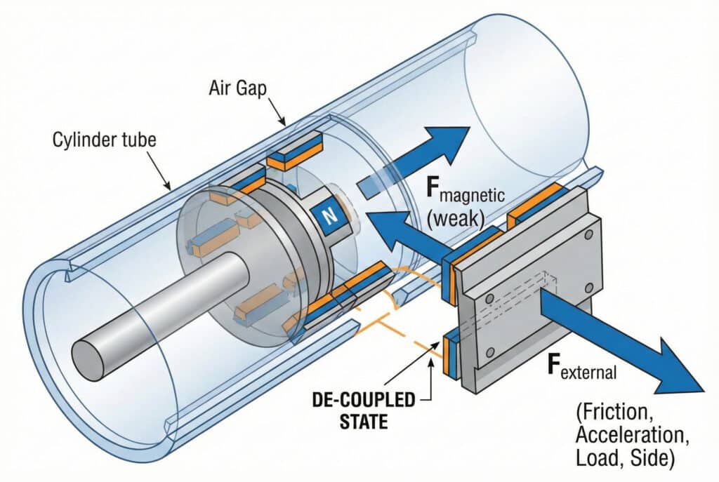
The Magnetic Coupling Principle
In magnetically coupled rodless cylinders, force transmission occurs through a non-contact magnetic field. This elegant design eliminates the need for seals penetrating the cylinder body, preventing air leakage and contamination.
How It Works:
- Internal magnets: Mounted on the pneumatic piston inside the sealed cylinder tube
- External magnets: Mounted on the carriage that travels outside the tube
- Magnetic attraction: Creates a coupling force that pulls the external carriage along with the internal piston
- Tube wall: Acts as the air gap, typically 1.5-3.5mm thick depending on cylinder size
The magnetic coupling force must overcome all resistance forces acting on the carriage to maintain synchronized movement.
Why De-coupling Happens: The Force Balance
Think of magnetic coupling like a magnetic “grip” between the internal and external components. When external forces exceed this grip strength, slippage occurs.
Critical Force Balance Equation:
When this inequality is violated, de-coupling occurs.
Real-World De-coupling Scenarios
I’ve investigated hundreds of de-coupling failures over my career, and they typically fall into these categories:
Sudden Overload (40% of cases):
The carriage encounters an unexpected obstruction or jam, creating instantaneous forces that exceed magnetic coupling capacity. This is the most dramatic failure mode—you hear a distinct “clunk” as the magnets slip.
Gradual Degradation (35% of cases):
Bearing wear, contamination, or misalignment gradually increases friction until it exceeds coupling force. This manifests as intermittent stalling that becomes progressively worse.
Design Inadequacy (25% of cases):
The cylinder was simply undersized for the application from the start. High acceleration rates, excessive side loads, or heavy payloads exceed the magnetic coupling specification.
The Consequences of De-coupling
Beyond immediate production stoppage, magnetic de-coupling causes several secondary problems:
| Consequence | Impact | Recovery Time | Typical Cost |
|---|---|---|---|
| Production stoppage | Immediate | 15-60 minutes | $500-$5,000 |
| Positioning loss | Requires re-homing | 5-15 minutes | $200-$1,000 |
| Magnet damage | Potential permanent weakening | N/A | $0-$800 |
| System recalibration | Lost production | 30-120 minutes | $1,000-$8,000 |
| Customer confidence | Long-term reputation damage | Ongoing | Incalculable 😟 |
What Forces Cause Magnetic De-coupling in Rodless Cylinders?
Multiple force components work together to challenge the magnetic coupling connection. ⚡
The primary forces causing magnetic de-coupling include: static and dynamic friction forces from bearings and seals (typically 5-15% of magnetic coupling force), inertial forces during acceleration and deceleration (F = ma, often the largest component), external payload forces including gravity and process loads, side loads creating moment forces that increase the effective air gap, and contamination-induced friction from dust or debris accumulation. Each force component must be calculated and summed to determine total coupling demand.
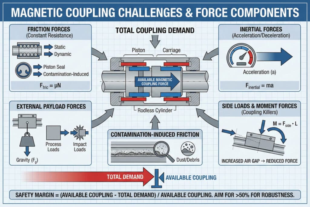
Friction Forces: The Constant Resistance
Friction is always present and represents the baseline force that must be overcome.
Components of Friction:
Bearing friction: The carriage rides on precision bearings or guide rails
- Linear ball bearings3: Coefficient μ ≈ 0.002-0.004
- Sliding bearings: Coefficient μ ≈ 0.05-0.15
- Typical force: 5-20N for standard cylinders
Seal friction: Internal piston seals create resistance
- Dynamic seal friction: 3-10N depending on bore size
- Increases with pressure and decreases with velocity
Contamination friction: Dust, debris, or dried lubricant
- Can increase total friction by 50-200%
- Highly variable and unpredictable
Friction Calculation Example:
For a 40mm bore cylinder with 10kg carriage load:
- Bearing friction:
- Seal friction: (typical for 40mm bore)
- Total baseline friction: ~5.3N
Inertial Forces: The Acceleration Challenge
Inertial forces during acceleration and deceleration often represent the largest component of coupling demand.
Where:
- m = total moving mass (carriage + payload + fixtures)
- a = acceleration rate
Practical Example:
I recently worked with Kevin, a machine builder in Ontario, whose pick-and-place application was experiencing de-coupling during rapid starts. His setup:
- Total moving mass: 8kg
- Acceleration rate: 15 m/s² (aggressive for pneumatics)
- Inertial force:
His 40mm bore cylinder had a magnetic coupling force of only 180N. After accounting for friction (15N) and a small external load (20N), his total demand was 155N—leaving only a 16% safety margin, well below the recommended 50%.
Acceleration Guidelines:
| Cylinder Bore | Max Magnetic Force | Recommended Max Acceleration (5kg load) |
|---|---|---|
| 25mm | 80N | 10 m/s² |
| 40mm | 180N | 25 m/s² |
| 63mm | 450N | 60 m/s² |
| 80mm | 800N | 100 m/s² |
External Load Forces
The payload and any process forces add directly to the coupling demand.
Types of External Loads:
Gravitational loads: When the cylinder operates vertically or at an angle
- Vertical mounting:
- For vertical operation (), full weight acts on coupling
Process forces: Pushing, pressing, or resistance during operation
- Insertion forces
- Friction from workpiece sliding
- Spring return forces
Impact loads: Sudden collisions or stops
- Can momentarily exceed steady-state forces by 3-5×
- Often the hidden cause of intermittent de-coupling
Side Loads and Moment Forces: The Coupling Killers
Side loads are particularly destructive to magnetic coupling because they create moment forces that effectively increase the air gap on one side.
The Physics of Side Load Impact:
When a side load is applied at a distance from the carriage center, it creates a tilting moment:
This moment causes the carriage to tilt slightly, increasing the air gap on one side. Since magnetic force decreases exponentially with gap distance, even small tilts dramatically reduce coupling force.
Magnetic Force vs. Gap Distance:
A 20% increase in air gap (from 2.0mm to 2.4mm) reduces magnetic force by approximately 36%!
Combined Force Analysis
Here’s a real-world example combining all force components:
Application: Horizontal material transfer with vertical load application
- Cylinder: 63mm bore, 2m stroke
- Magnetic coupling force: 450N
- Moving mass: 12kg
- Acceleration: 8 m/s²
- External load: 15kg (applied 100mm above carriage center)
- Side load: 50N
Force Calculation:
- Friction: 18N
- Inertial: 12kg × 8 m/s² = 96N
- External load inertia: 15kg × 8 m/s² = 120N
- Side load moment effect: ~15% reduction in coupling = 67.5N equivalent
- Total demand: 18 + 96 + 120 + 67.5 = 301.5N
- Available coupling: 450N
- Safety margin: (450 – 301.5) / 450 = 33% ✅
This 33% margin is acceptable but leaves little room for contamination or wear.
How Do You Calculate the Magnetic Coupling Safety Margin?
Proper safety margin calculation prevents de-coupling failures and ensures long-term reliability. 📊
To calculate magnetic coupling safety margin: sum all force components (friction + inertial + external loads + side load effects), compare to the cylinder’s rated magnetic coupling force, and ensure the safety margin exceeds 50% for standard applications or 100% for critical applications. The formula is: . This margin accounts for manufacturing tolerances, wear over time, contamination effects, and unexpected load variations.
![A technical infographic illustrating the magnetic coupling safety margin calculation. It displays the formula: Safety Margin (%) = [(F_magnetic - F_total_demand) / F_magnetic] × 100. A breakdown shows F_total_demand as the sum of Friction (F_f), Inertial (F_i), External Loads (F_e), and Side Load Effects (F_s), each with a corresponding icon. A visual gauge on the right shows the "Rated Magnetic Coupling Force" with a red bar for "Total Force Demand" and a green zone for the "Safety Margin," indicating it accounts for tolerances, wear, contamination, and load variations, with recommended margins for standard (>50%) and critical (>100%) applications.](https://rodlesspneumatic.com/wp-content/uploads/2026/01/Magnetic-Coupling-Safety-Margin-Calculation-Reliability-1024x687.jpg)
Step-by-Step Calculation Methodology
Let me walk you through the exact process we use when sizing cylinders for our clients:
Step 1: Identify All Force Components
Create a comprehensive force inventory:
- Carriage mass: _____ kg
- Payload mass: _____ kg
- Maximum acceleration: _____ m/s²
- External process forces: _____ N
- Side loads: _____ N at _____ mm distance
- Mounting angle: _____ degrees from horizontal
Step 2: Calculate Each Force Component
Use these formulas:
- Friction force: (estimate) or measure directly
- Inertial force:
- Gravity component:
- External forces:
- Side load penalty: (conservative multiplier)
Step 3: Sum Total Force Demand
Step 4: Compare to Magnetic Coupling Force
Find the cylinder’s rated magnetic coupling force from specifications:
- Bepto 25mm bore: 80N
- Bepto 40mm bore: 180N
- Bepto 63mm bore: 450N
- Bepto 80mm bore: 800N
Step 5: Calculate Safety Margin
Worked Example: Complete Calculation
Let me share a recent sizing calculation for a client in the automotive industry:
Application Specifications:
- Function: Transfer welding fixture between stations
- Stroke: 1,500mm horizontal
- Cycle time: 2 seconds (0.5s acceleration, 1.0s constant velocity, 0.5s deceleration)
- Carriage mass: 6kg
- Fixture mass: 18kg
- Side load: 40N at 120mm above carriage center
- No external process forces
Calculations:
Maximum acceleration:
- Distance during acceleration:
- Using :
Inertial force:
Friction force (estimated):
Side load effect:
- Moment:
- Equivalent force penalty:
Total force demand:
Cylinder selection:
- 40mm bore (180N): ❌ INADEQUATE
- 63mm bore (450N): ✅ ACCEPTABLE
Recommendation: 63mm bore Bepto rodless cylinder
Safety Margin Guidelines
Based on decades of field experience, here are our recommended safety margins:
| Application Type | Minimum Safety Margin | Recommended Margin | Rationale |
|---|---|---|---|
| Laboratory/Clean | 30% | 50% | Controlled environment, low contamination |
| General Industrial | 50% | 75% | Standard manufacturing environment 🏭 |
| Heavy Duty | 75% | 100% | High contamination, wear, or shock loads |
| Critical Process | 100% | 150% | Zero tolerance for failure, 24/7 operation ⭐ |
Temperature and Wear Considerations
Two often-overlooked factors affect magnetic coupling force over time:
Temperature Effects:
Neodymium magnets5 (used in most rodless cylinders) lose approximately 0.11% of their strength per °C above 20°C.
For a cylinder operating at 60°C:
- Temperature rise: 40°C
- Magnetic force reduction:
- Effective coupling force:
Wear and Aging:
Over 3-5 years of operation, magnetic coupling force typically decreases by 5-10% due to:
- Magnet aging and demagnetization
- Bearing wear increasing friction
- Seal wear increasing friction
- Contamination accumulation
Adjusted Safety Margin Calculation:
Always account for these factors:
This 10% derating accounts for temperature and aging effects.
Bepto vs. OEM: Magnetic Coupling Performance
Our Bepto cylinders consistently outperform OEM equivalents in magnetic coupling force:
| Bore Size | OEM Typical | Bepto Standard | Bepto Advantage |
|---|---|---|---|
| 25mm | 70N | 80N | +14% 📈 |
| 40mm | 160N | 180N | +13% |
| 63mm | 400N | 450N | +13% |
| 80mm | 700N | 800N | +14% |
This performance advantage, combined with our 50% lower pricing, means you get superior reliability at half the cost. 💰
What Design Strategies Prevent Magnetic De-coupling Failures?
Smart design choices eliminate de-coupling issues before they occur. 🛡️
Effective strategies to prevent magnetic de-coupling include: selecting cylinders with 50-100% safety margin above calculated forces, minimizing side loads through proper mounting and load centering, reducing acceleration rates to decrease inertial forces, implementing external guide rails to absorb side loads, using progressive acceleration profiles instead of instantaneous starts, maintaining clean operating environments to minimize friction, and establishing preventive maintenance schedules to address wear before it causes failures. Combining multiple strategies provides robust protection against de-coupling.
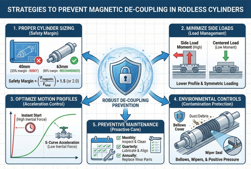
Strategy 1: Proper Cylinder Sizing
The foundation of de-coupling prevention is selecting the right cylinder from the start.
Sizing Best Practices:
- Calculate conservatively: Use worst-case values for all parameters
- Add safety margin: Minimum 50%, preferably 75-100%
- Consider future changes: Will loads increase? Will cycle times decrease?
- Account for environment: High temperature? Contamination? Wear?
I recently consulted with Patricia, an equipment designer in Illinois, who was specifying cylinders for a new production line. Her initial calculations showed a 40mm bore would work with 35% safety margin. I convinced her to upgrade to 63mm bore with 80% margin. Six months after installation, her client requested 25% faster cycle times—a change that would have caused constant de-coupling with the 40mm cylinder but was easily accommodated with the 63mm.
Strategy 2: Minimize Side Loads
Side loads are the enemy of magnetic coupling. Every design decision should aim to reduce them.
Design Techniques:
Lower mounting height: Mount loads as close to the carriage center as possible
- Every 10mm closer reduces moment by 10mm × load
- Use low-profile fixtures and tooling
Symmetric loading: Balance loads on both sides of the carriage
- Prevents tilting moments
- Maintains consistent air gap
External guide rails: Add supplementary linear guides
- Absorb side loads completely
- Allow magnetic coupling to focus on axial forces only
- Increases system cost by 30-40% but eliminates de-coupling risk
Counterbalancing: Use weights or springs to offset asymmetric loads
- Particularly effective for vertical applications
- Reduces net side load to near zero
Strategy 3: Optimize Motion Profiles
How you accelerate and decelerate dramatically affects coupling demand.
Acceleration Profile Options:
| Profile Type | Peak Force | Smoothness | Cycle Time | Best For |
|---|---|---|---|---|
| Instant (bang-bang) | 100% | Poor | Fastest | Only with large safety margins |
| Linear ramp | 70% | Good | Fast | General industrial use ⭐ |
| S-curve | 50% | Excellent | Moderate | Precision applications |
| Custom optimized | 40% | Excellent | Optimized | Critical applications 🎯 |
Practical Implementation:
Most pneumatic systems use simple on/off valves, giving instant acceleration. By adding:
- Flow control valves: Reduce acceleration by limiting air flow
- Soft-start valves: Provide gradual pressure buildup
- Proportional valves: Enable custom acceleration profiles
You can reduce peak inertial forces by 30-50% with minimal cost increase.
Strategy 4: Environmental Controls
Contamination is a silent killer of magnetic coupling systems.
Protection Strategies:
Bellows covers: Protect the cylinder body and carriage from dust and debris
- Cost: $50-150 per cylinder
- Effectiveness: 90% reduction in contamination
Wiper seals: Remove contaminants before they enter bearing surfaces
- Standard on Bepto cylinders
- Extends bearing life by 2-3×
Positive pressure: Maintain slight air pressure in enclosures
- Prevents dust ingress
- Common in food processing and pharmaceutical applications
Regular cleaning: Establish cleaning schedules
- Weekly wipe-down of exposed surfaces
- Monthly detailed cleaning
- Prevents gradual friction increase
Strategy 5: Preventive Maintenance Program
Proactive maintenance prevents the gradual degradation that leads to de-coupling.
Essential Maintenance Tasks:
Monthly:
- Visual inspection for contamination
- Listen for unusual noise (indicates bearing wear)
- Verify smooth motion throughout stroke
- Check for any hesitation or sticking
Quarterly:
- Clean all exposed surfaces
- Lubricate per manufacturer specifications
- Verify mounting alignment
- Test at maximum rated speed and load
Annually:
- Replace wear components (seals, bearings if accessible)
- Detailed inspection of magnetic coupling area
- Verify magnetic coupling force (if test equipment available)
- Update documentation and trend analysis
Real-World Success: Comprehensive Approach
Let me share how combining these strategies transformed a problematic application. Marcus, a plant engineer at a food processing facility in California, was experiencing 2-3 de-coupling events per week on his packaging line.
Original System Issues:
- 40mm bore cylinders operating at 95% of magnetic coupling capacity
- Heavy tooling mounted 150mm above carriage center
- Dusty environment with flour contamination
- Instant acceleration profiles
- No preventive maintenance program
Our Comprehensive Solution:
- Upgraded to 63mm Bepto cylinders: Increased magnetic coupling from 160N to 450N (+181%)
- Redesigned tooling: Lowered mounting height to 80mm, reducing side load moment by 47%
- Added bellows covers: Protected from flour dust contamination
- Installed flow controls: Reduced acceleration by 40%, cutting inertial forces proportionally
- Implemented maintenance schedule: Monthly cleaning and quarterly detailed inspection
Results After 12 Months:
- De-coupling events: Zero ✅
- Unplanned downtime: Reduced from 156 hours/year to 0 hours
- Maintenance costs: $8,400/year (scheduled) vs. $23,000/year (reactive)
- Production efficiency: Increased 4.2%
- ROI: 340% in first year 💰
Bepto’s De-coupling Prevention Advantage
When you choose Bepto rodless cylinders, you get built-in de-coupling prevention:
Standard Features:
- 13-14% higher magnetic coupling force than OEM equivalents
- Precision-ground bearing surfaces (lower friction)
- Advanced wiper seal design (contamination protection)
- Optimized magnetic circuit (maximum force with minimum magnet material)
- Comprehensive technical documentation (proper sizing guidance)
Support Services:
- Free application engineering consultation
- Force calculation verification
- Motion profile optimization recommendations
- Preventive maintenance training
- 24/7 technical
Conclusion
Magnetic de-coupling doesn’t have to be a mystery or an inevitable problem—by understanding the physics, calculating forces accurately, maintaining adequate safety margins, and implementing smart design strategies, you can achieve years of reliable, trouble-free operation from your magnetically coupled rodless cylinders. 🎯
FAQs About Magnetic De-coupling Forces
What is the typical magnetic coupling force for different cylinder sizes?
Magnetic coupling forces typically range from 80N for 25mm bore cylinders to 800N for 80mm bore cylinders, with the force roughly proportional to the cylinder’s cross-sectional area since larger bores accommodate more or stronger magnets. Specifically, our Bepto cylinders provide: 25mm bore = 80N, 40mm bore = 180N, 63mm bore = 450N, and 80mm bore = 800N. These values represent the maximum static force before de-coupling occurs under ideal conditions (clean, new, room temperature). In practice, you should never design to use more than 50-70% of these values to account for dynamic conditions, wear, contamination, and temperature effects.
Can magnetic coupling force be increased after installation?
No, the magnetic coupling force is fixed by the cylinder’s design and cannot be increased after installation, as it’s determined by the magnet material, magnet size, number of magnet poles, and air gap thickness—all of which are built into the cylinder structure. If you’re experiencing de-coupling with an installed cylinder, your only options are to: reduce the forces acting on the system (lower acceleration, reduce loads, minimize side forces), improve operating conditions (reduce contamination, improve alignment), or replace with a larger bore cylinder with higher coupling force. This is why proper initial sizing with adequate safety margin is critical. At Bepto, we offer free application review to verify your cylinder selection before purchase, preventing costly mistakes.
How does temperature affect magnetic coupling strength?
Temperature significantly affects magnetic coupling strength, with neodymium magnets (used in most rodless cylinders) losing approximately 0.11% of their strength per degree Celsius above 20°C, and potentially suffering permanent demagnetization if exposed to temperatures exceeding 80-120°C depending on magnet grade. For example, a cylinder operating at 60°C experiences about 4.4% reduction in coupling force compared to room temperature operation. In high-temperature applications (above 60°C), you should either: select a cylinder with extra safety margin to compensate, use cylinders with high-temperature magnet grades (available in our Bepto HT series), or implement cooling measures. Conversely, magnetic force increases slightly at lower temperatures, though this is rarely a concern in industrial applications.
What’s the difference between static and dynamic de-coupling force?
Static de-coupling force is the maximum force that can be applied to a stationary carriage before the magnetic coupling breaks, while dynamic de-coupling force is typically 10-20% lower due to factors like vibration, bearing friction variations, and magnetic field dynamics during motion. Static force is what manufacturers specify in datasheets because it’s easily measured and represents best-case performance. However, real applications involve dynamic conditions—acceleration, vibration, varying friction—that reduce effective coupling strength. This is another reason why adequate safety margin is essential. When calculating your force requirements, always use dynamic conditions (including acceleration forces) and compare against the static coupling specification with at least 50% margin.
How do you diagnose the cause of magnetic de-coupling events?
To diagnose de-coupling causes, systematically evaluate: timing (does it occur at specific stroke positions or randomly?), load conditions (does it happen under maximum load or acceleration?), environmental factors (correlation with temperature or contamination?), and frequency (increasing over time suggests wear, random suggests overload). Start by calculating your theoretical force requirements and comparing to cylinder capacity—if you’re operating above 70% capacity, the cylinder is simply undersized. If capacity is adequate, investigate: bearing wear (check for roughness or noise), contamination (inspect for debris accumulation), misalignment (verify mounting), and side loads (measure or calculate moment forces). Document when de-coupling occurs and under what conditions—patterns reveal root causes.
-
Learn more about the fundamental operating principles and unique design benefits of magnetically coupled rodless cylinders. ↩
-
Gain a deeper understanding of magnetic circuit design and how magnetic flux is optimized for maximum force transmission. ↩
-
Reference detailed specifications and friction coefficients for various types of linear ball bearings used in industrial carriages. ↩
-
Explore the physical principles of Newton’s second law and how force relates to mass and acceleration in mechanical systems. ↩
-
Discover the material properties and performance characteristics of high-strength neodymium magnets used in industrial automation. ↩
