

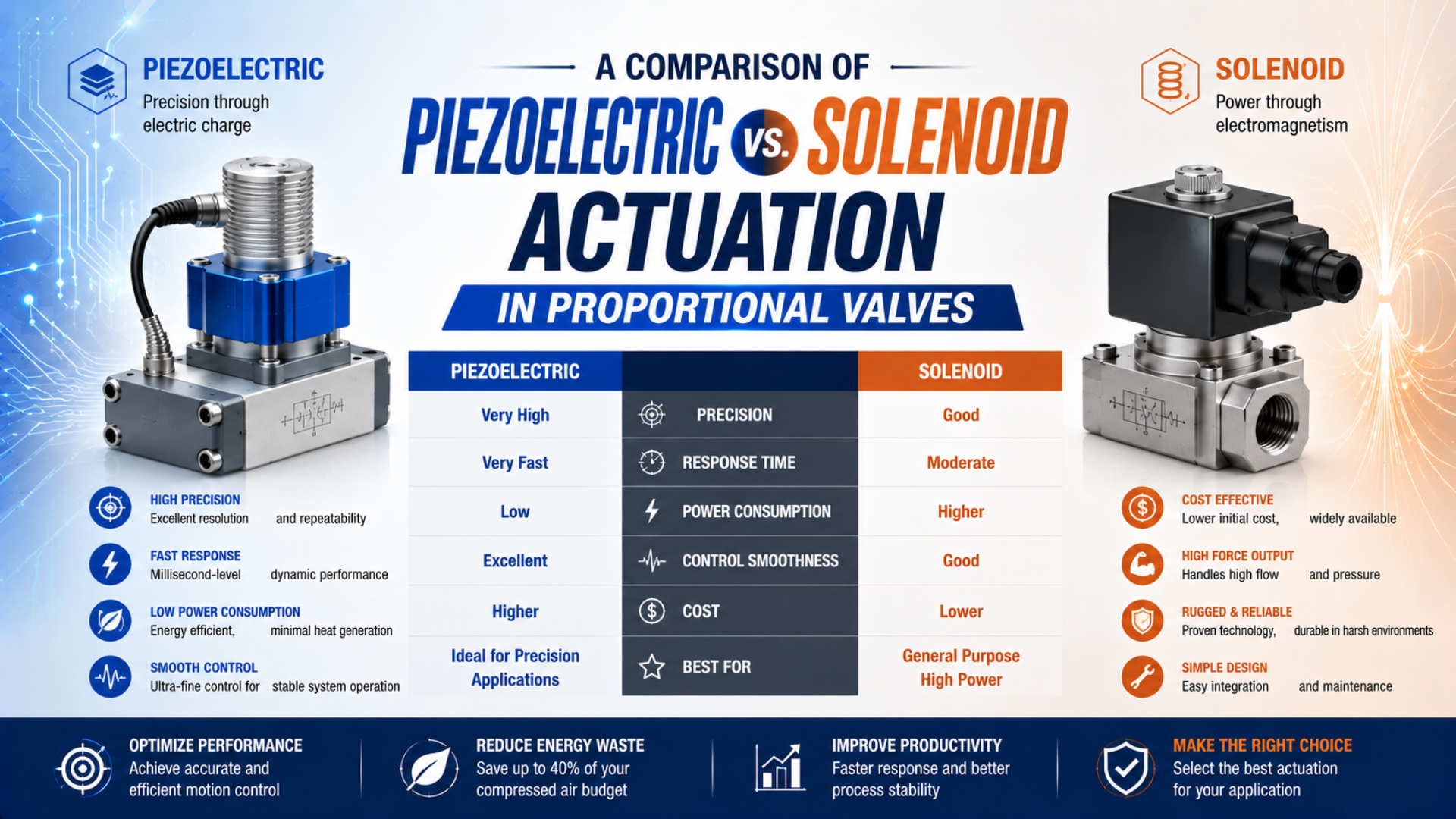
Piezoelectric vs. solenoid actuation in proportional valves should be compared as complete devices at the same pressure, flow, command, load, and test definition. Piezo technology usually favors low holding energy, low heat, quiet operation, and compact low-flow control. Solenoid technology usually offers broader flow and pressure choices, familiar industrial interfaces, and stronger direct actuation. Neither architecture wins every duty.
Separate ISO frameworks cover electro-pneumatic continuous flow and pressure control. That matters because electrical actuator speed, valve shifting time, pressure-settling time, and mass-flow response are not interchangeable measurements (ISO 10041-2, 2010; ISO 10094-2, 2021).
Key Takeaways
- Compare complete valve assemblies, not bare actuator physics.
- Match flow, pressure, hysteresis, response definition, electronics, and environment.
- Piezo valves minimize holding energy; high-frequency movement still consumes energy.
- Solenoid proportional valves can be fast, efficient, and precise when sized for the duty.
For the broader distinction between pressure, flow, and directional control, start with the proportional valve selection guide. This article stays narrower: it compares the two electrical actuation methods inside proportional pneumatic valves.
Why Doesn’t Actuator Physics Determine Complete Valve Performance?
For electro-pneumatic continuous flow valves, ISO 10041-2 standardizes the tests. Pressure control valves fall under ISO 10094-2. These separate scopes show why a bare actuator’s displacement speed cannot establish a valve’s usable flow response, pressure settling, hysteresis, or repeatability (ISO 10041-2, 2010; ISO 10094-2, 2021).
Proportional valves form a chain of interacting parts. Command signals pass through drive electronics, move an actuator, change an orifice or spool position, alter gas flow, and finally change a measured process variable. Pneumatic volume, pressure ratio, sensor filtering, controller tuning, and downstream restriction can dominate what the machine sees. Read the whole chain. This boundary corrects two common comparison errors. Transferring nanometre-scale positioning claims from a piezo stage to the pressure or flow resolution of a valve is the first. Comparing a direct-acting piezo microvalve with a much larger solenoid spool valve, then treating the result as an inherent technology ratio, is the second.
Festo describes piezo benders for pneumatic valves with motion and force ranges that differ sharply from piezo stack transducers used in liquid injection or micro-positioning. Its white paper cautions that all piezo benefits cannot be exploited simultaneously in one valve design (Festo, Piezo Technology in Pneumatic Valves, 2017).
Therefore, use one complete valve-electronics configuration as the comparison unit, not piezoelectric material versus copper coil. Compare it with another complete configuration tested at the operating point the application will use.
From our analysis of current ISO test scopes and current manufacturer data, the most defensible comparison keeps four boundaries visible: valve function, complete assembly, operating point, and measurement endpoint. Removing any one of them can turn a valid product result into a false technology-wide claim.
How Do the Two Actuation Paths Work Inside Proportional Valves?
Festo’s 2025 VEMP data sheet lists piezo-valve nominal flow values from 18 to 29 L/min and operating pressures up to 1.7 bar, depending on variant. These product-level limits are more useful than generic actuator claims because they connect the piezo bender to a real valve function (Festo VEMP, 2025).
A piezoelectric proportional valve is a valve whose piezo element deforms in response to an electric field and varies a pneumatic opening. Pneumatic designs commonly use a bending element that opens or closes a small seat. Electrically, the element behaves like a capacitor: current flows during charging, then falls once the commanded state is reached. Resetting requires controlled discharge. A solenoid proportional valve uses regulated coil current to create magnetic force on an armature or plunger. Its movement changes the metering opening directly or controls a pilot stage. Current control or a PWM driver compensates for supply variation and lets the valve occupy intermediate positions instead of acting only as an on-off device.
Metering mechanics after the actuator still matter. Poppets, needles, diaphragms, and spools have different leakage, friction, balance, travel, contamination sensitivity, and force requirements. Pilot operation can extend flow capacity but adds pneumatic dynamics and may impose minimum pressure conditions. Our direct-acting versus pilot-operated valve guide explains that separate design choice.
Check the exact construction.
How Should Response and Control Quality Be Compared?
Bürkert’s Type 2852 solenoid proportional valve specifies an actuating time below 10 ms, repeat accuracy below 1% of full scale, and response sensitivity below 0.1% under stated conditions. That one data sheet disproves any universal claim that solenoid proportional valves are inherently slow or imprecise (Bürkert Type 2852, 2026).
Start by identifying what the time value measures. Electrical delay, initial armature movement, 10-to-90 percent valve travel, flow rise time, pressure settling, and loaded machine response are different results. Directional-valve shifting time is standardized by ISO 12238:2023, but continuous flow and pressure valves belong to the ISO 10041 and ISO 10094 test families (ISO 12238, 2023).
One time value cannot represent all of them.
Then compare the rest of the control data:
| Data-sheet item | What it reveals | Comparison condition |
|---|---|---|
| Actuating or response time | Dynamic movement after a defined command | Same amplitude, pressure, temperature, and load |
| Hysteresis | Output difference on rising and falling commands | Same flow or pressure measurement method |
| Repeatability | Variation after repeated equal commands | Same cycles, warm-up, and environmental state |
| Sensitivity or threshold | Smallest command change producing useful output | Same noise filtering and measurement resolution |
| Control range | Usable span between threshold and saturation | Same upstream and downstream conditions |
| Leakage | Uncommanded internal or external flow | Same pressure, medium, and valve state |
Do not confuse sensor resolution with valve accuracy. Digital controllers can accept a fine setpoint, but friction, seat geometry, flow noise, and pressure variation limit the actual output. Likewise, a fast actuator does not guarantee fast pressure control when a large downstream volume must fill or exhaust.
For cylinder positioning, the valve is only one part of the loop. The proportional valve position-control guide covers feedback, tuning, dead volume, and loaded-axis acceptance.
A defensible response-time comparison names both endpoints: the electrical event that starts the test and the pneumatic or mechanical event that ends it. Numbers without those endpoints are not portable specifications.
How Should Power and Thermal Behavior Be Compared?
Festo lists a complete VEMD piezo mass-flow controller at a maximum electrical consumption of 1 W. Bürkert lists the solenoid Type 2852 at 2.8 W and 3.4 W maximum. These figures demonstrate a real low-power advantage in that comparison, but not a universal ratio across valve sizes (Festo VEMD, 2026; Bürkert Type 2852, 2026).
Piezo elements draw charge when their command changes and need little or no actuator current to maintain a static state. Drivers, sensors, communications, and closed-loop controllers can still consume power. Rapid command changes repeatedly charge and discharge the element, so dynamic energy rises with capacitance, voltage swing, and command frequency. Static and dynamic duties differ. Solenoids require current to maintain magnetic force. Current regulation, peak-and-hold control, or an efficient mechanical and magnetic design can reduce steady power. Coil resistance increases with temperature, and uncontrolled voltage drive can change force as the coil warms. Good proportional electronics therefore control current rather than assuming voltage alone defines valve position.
Heat matters beyond electricity cost. It can shift resistance, seal behavior, sensor readings, and the surrounding enclosure temperature. The correct thermal comparison records ambient temperature, mounting density, duty cycle, command profile, ventilation, and whether the published value covers only the actuator or the complete controller.
The low-power solenoid valve guide explains peak-and-hold and coil-power strategies. Here, the purchasing rule is simpler: compare average system power over the real command profile, not only holding current or a nameplate maximum.
Low holding energy is most valuable when a valve spends long periods at a steady command. In a fast-modulating loop, switching energy, driver losses, sensor power, and control frequency become part of the same energy budget.
What Pressure and Flow Envelope Can Each Architecture Cover?
Festo’s proportional-pneumatics catalog lists the piezo VEMD at 20 L/min and 1 W. Its MPYE solenoid spool family reaches 2,000 L/min with higher model-dependent power. This is a product-family example, not an inherent limit, but it shows why flow capacity and power must be reviewed together (Festo, Proportional Pneumatics, 2021).
Piezo benders provide small motion at low electrical energy, which suits small seats, low leakage targets, quiet operation, and compact low-flow control. Higher flow may require multiple elements, a pilot stage, a larger pressure-balanced structure, or a different piezo actuator form. Each choice changes response and leakage. Solenoids can provide more travel and direct force across a broad catalog range. A larger coil, magnetic circuit, or pilot arrangement can operate a larger orifice or spool. The tradeoffs can include heat, weight, current demand, magnetic-field sensitivity, and a larger package.
Neither architecture determines pressure rating by itself. Seat diameter, pressure balance, body strength, seal materials, pilot ratio, leakage target, and medium compatibility all contribute. Festo’s VEMP variants, for example, combine low nominal flow with model-dependent pressures up to 1.7 bar. Bürkert’s Type 2852 solenoid example is rated to 7 bar. They serve different envelopes and should not be presented as substitutes without a full duty comparison.
Start with the pneumatic envelope.
Port thread is also insufficient. Ask for standardized or fully defined flow data at known upstream and downstream pressures. A high maximum flow can still provide poor low-command resolution if the valve is oversized. The proportional flow-control guide explains why command range and installed restrictions affect usable cylinder control.
Piezoelectric vs. Solenoid Actuation Selection Matrix
Under ISO 10094-1, proportional pressure valves with and without electronic pressure feedback are distinct configurations. That distinction is more useful than choosing by actuator alone: the application first defines pressure, flow, or directional control, then the required feedback and performance envelope (ISO 10094-1, 2021).
| Application condition | Piezoelectric actuation tends to fit | Solenoid actuation tends to fit | Verify before selection |
|---|---|---|---|
| Battery-powered or heat-sensitive device | Strong fit when flow and pressure remain within the piezo valve range | Possible with optimized low-power drive | Complete average power and enclosure temperature |
| Quiet medical or laboratory gas control | Strong fit for compact, silent low-flow regulation | Suitable when approved product and noise are acceptable | Medium approval, leakage, cleaning, and fault behavior |
| High industrial flow or broad pressure range | Possible with a pilot or specialized design | Broad catalog availability | Flow curve, pressure ratio, pilot demand, and heat |
| Fast closed-loop pressure or flow control | Strong when the complete valve has verified dynamics | Strong when the solenoid valve and driver meet the bandwidth | Same test definition, volume, sensor, and controller |
| Magnetic-field-sensitive equipment | Piezo can avoid a magnetic actuator | Requires field-compatibility review | Materials, driver location, and installation field strength |
| Dirty or harsh industrial environment | Product-specific; small seats may need cleaner media | Product-specific; moving parts still need clean air | Filtration, IP configuration, shock, vibration, and temperature |
| Cost-sensitive standard automation | Evaluate total electronics and integration cost | Often offers more sourcing choices | Delivered assembly, driver, commissioning, and lifecycle cost |
Use piezoelectric actuation when low heat, low static energy, quiet operation, compact packaging, or magnetic immunity materially controls the design and the selected valve meets the pneumatic envelope. Use solenoid actuation when flow, pressure, sourcing breadth, familiar industrial electronics, or direct force dominates and the selected model meets the control-quality target.
Specification and RFQ Checklist
Reliability standard ISO 19973-2 treats directional-valve life as a tested result reported in cycles, not a universal material property. Procurement specifications should therefore request the exact model’s test basis rather than claiming that one actuation technology always lasts millions or billions of cycles (ISO 19973-2, 2015).
Send suppliers one controlled operating-point sheet:
- Valve function: pressure, flow, or direction; ports; safe state.
- Pneumatic duty: name the medium, minimum and maximum inlet pressure, downstream pressure or volume, required flow range, leakage limit, pilot source, pilot exhaust, and every operating point that will be used for acceptance.
- Control performance: command step, response endpoint, settling band, hysteresis, repeatability, sensitivity, deadband, and acceptable warm-up drift.
- Electrical interface: supply, analog or digital command, input impedance, update rate, driver location, feedback output, alarms, and connector.
- Energy profile: static command duration, modulation frequency, average movement, peak demand, enclosure temperature, and allowed heat rise.
- Environment: ambient and medium temperature, filtration, lubrication, humidity, washdown, shock, vibration, magnetic field, corrosion, and installation orientation.
- Evidence: exact part number, current data sheet, characteristic curves, test methods, variant approvals, material declarations, and change-control notice.
- Acceptance test: reproduce the production medium or an approved substitute, defined pressure conditions, representative downstream volume, command waveform, warm-up state, calibrated instruments, sample size, number of cycles, calculation method, and explicit pass limits for every measured output.
Ask one additional question: does the quoted performance cover the bare valve, valve plus driver, or a closed-loop controller with sensor? A clear system boundary prevents most misleading comparisons.
Do not accept an undefined boundary.
For response-time acceptance, use the definitions in the pneumatic valve shifting-time guide. For a pressure-control application, the proportional pressure-regulator guide provides the next layer of regulator-specific checks.
Piezoelectric vs. Solenoid Proportional Valve FAQs
Four ISO test scopes separately address continuous flow, continuous pressure, directional shifting, and directional-valve reliability. They explain the FAQ answers below: a technology label cannot replace a defined valve function, operating point, measurement endpoint, and exact product record (ISO 10041-2, 2010; ISO 10094-2, 2021).
Are piezoelectric proportional valves always faster than solenoid valves?
No. A piezo element can move very quickly, but the complete valve response also depends on the seat, pilot stage, electronics, pneumatic volume, pressure ratio, sensor, and response definition. Compare model-specific curves or tests at the same command step and operating point. Bürkert, for example, specifies under 10 ms for one solenoid proportional valve.
Do piezoelectric valves consume zero power while holding position?
The piezo actuator needs little or no continuing current after it is charged, but a complete valve or regulator may include a driver, sensor, controller, communications, and diagnostics. Those circuits consume power. Frequent command changes also require repeated charging and discharging, so average energy depends on command frequency and voltage swing.
Are solenoid proportional valves only suitable for on-off control?
No. A proportional solenoid valve regulates coil current so the armature, plunger, needle, or spool can occupy intermediate positions. It is different from a simple switching valve. Its usable control quality depends on current regulation, magnetic design, friction, pressure forces, hysteresis, sensitivity, and the characteristic curve of the exact valve.
Can actuator resolution predict pressure or flow accuracy?
No. Actuator displacement resolution describes only one element in the command-to-output chain. Valve geometry, friction, leakage, gas compressibility, pressure variation, sensors, filtering, and controller behavior affect the measured pressure or flow. Use the complete valve’s hysteresis, repeatability, sensitivity, and dynamic data under conditions that match the application.
Which actuation method has the longer service life?
Neither has a universal lifetime advantage. Piezo benders avoid a sliding magnetic armature. Solenoid designs can also achieve long life with suitable materials, current control, filtration, and loading. Request cycle-test conditions, failure criteria, confidence information, and the exact tested configuration. Application contamination, temperature, pressure, and modulation rate can change the result.
Sources and technical references
- ISO, ISO 10041-2:2010, test methods and presentation of results for electro-pneumatic continuous flow control valves. Retrieved 2026-07-22.
- ISO, ISO 10094-1:2021, supplier-literature characteristics. Retrieved 2026-07-22.
- ISO, ISO 10094-2:2021, comparative test methods for continuous pressure control valves. Retrieved 2026-07-22.
- ISO, ISO 12238:2023, shifting-time tests for electrically or pneumatically operated directional control valves. Retrieved 2026-07-22.
- ISO, ISO 19973-2:2015, reliability assessment and cycle reporting for pneumatic directional control valves. Retrieved 2026-07-22.
- Festo, Piezo Technology in Pneumatic Valves, piezo benders, disc translators, and stack transducers; approximate charging energy; drive voltage; holding behavior; switching characteristics; magnetic-field behavior; and the warning that one valve cannot exploit every potential piezo advantage simultaneously. Retrieved 2026-07-22.
- Festo, Piezo Valve VEMP, model-specific pressure, flow, voltage, temperature, and operating data. Retrieved 2026-07-22.
- Festo, Mass Flow Controller VEMD, complete piezo-controller flow and electrical specifications. Retrieved 2026-07-22.
- Festo, Proportional Pneumatics, cross-family pressure, flow, power, and design data. Retrieved 2026-07-22.
- Bürkert, Type 2852 Data Sheet, solenoid proportional-valve response, repeatability, sensitivity, flow, pressure, and power data. Retrieved 2026-07-22.