

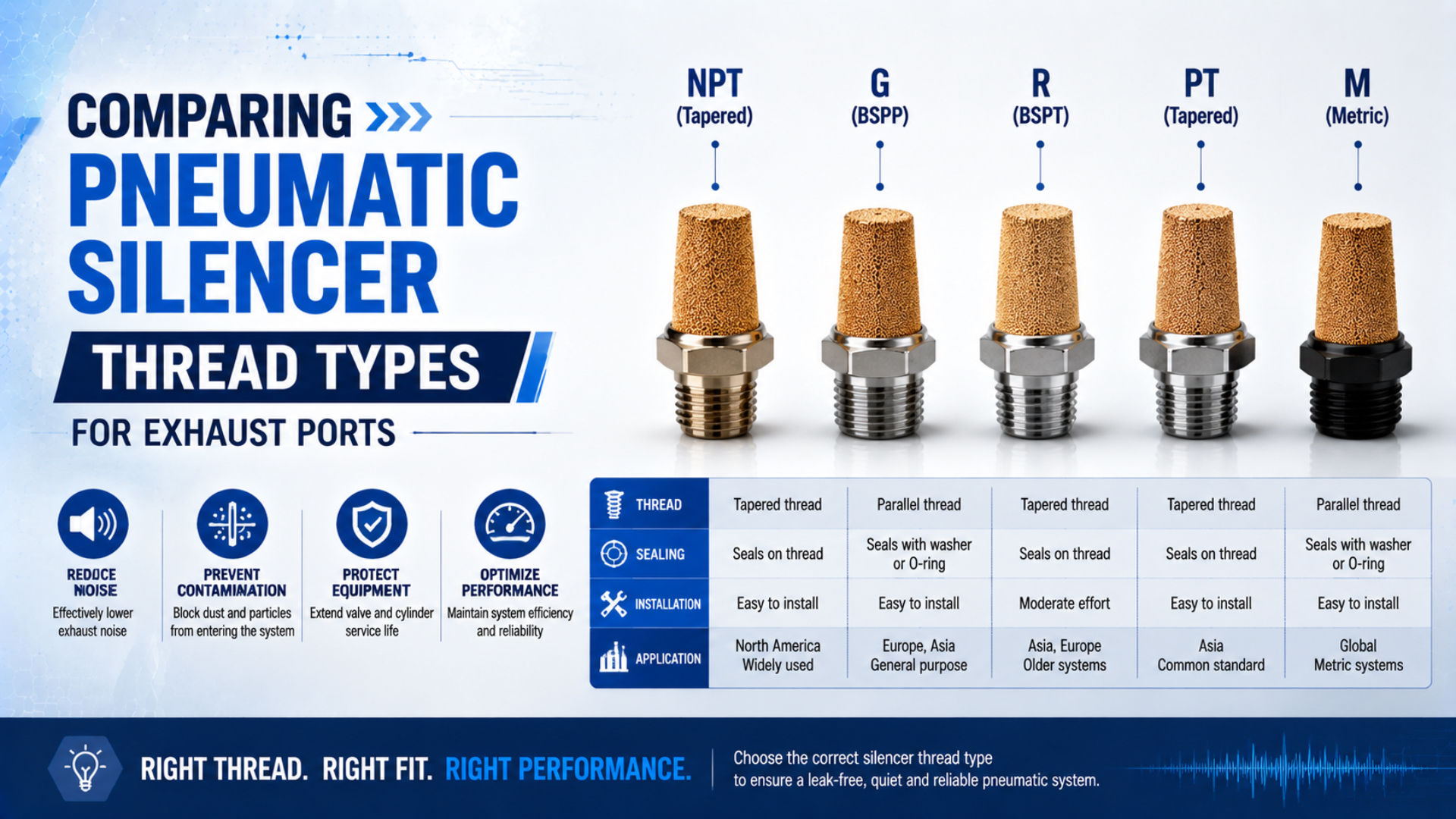
Pneumatic silencer thread types cannot be selected from nominal size or equipment origin alone. A safe replacement matches the exact thread designation, mating geometry, sealing interface, installation instruction, and exhaust capacity. A part that starts by hand can still have the wrong pitch, taper, seal, or flow rating.
Treat the job as an exhaust-component replacement, not a thread-identification quiz. Confirm the valve part number and drawing first. Measure an unknown port only when documentation is unavailable, then check the proposed silencer’s flow, back pressure, noise data, material, temperature range, and body clearance before release.
Key Takeaways
- ASME B1.20.1, ISO 7-1, ISO 228-1, and ISO 261 describe different thread families.
- A nominal quarter-inch label does not establish compatibility.
- Seal location and tightening method are product-specific.
- The correct thread can still leave an undersized or unsuitable silencer.
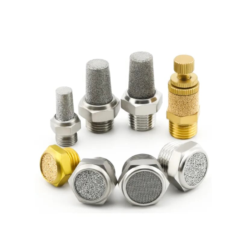
Silencer bodies can look alike even when their connection, material, flow capacity, and installation limits differ.
Which Thread Designation Is Actually on the Exhaust Port?
ASME B1.20.1 covers 5 general-purpose inch pipe-thread forms, including NPT, while ISO 7-1 and ISO 228-1 govern different pipe-thread systems. The first replacement step is therefore to recover the complete designation from the valve drawing or manual, not to translate every inch-looking port into NPT (ASME B1.20.1; ISO 7-1; ISO 228-1).
The four groups commonly encountered on screw-in pneumatic silencers are:
| Connection group | Governing reference | Geometry to record | What the label does not prove |
|---|---|---|---|
| NPT | ASME B1.20.1 | Inch tapered pipe thread; record the full NPT size | Compatibility with ISO 7 or G threads |
| R, Rc, Rp | ISO 7-1 | R is an external taper; Rc is an internal taper; Rp is an internal parallel thread | That the informal label “BSP” identifies the mating pair |
| G | ISO 228-1 | Parallel external and internal fastening pipe threads | The separate sealing surface or seal supplied by the product |
| M | ISO 261 with product drawing | Metric diameter and pitch, such as M5 × 0.8 | The pneumatic sealing method, port depth, or body seating feature |
A complete thread designation is the standard-family, nominal-size, and form record used to select or inspect the mating connection. 1/4, BSP, metric, and looks like NPT are incomplete purchase descriptions.
ISO 261 defines the general plan for metric M threads, but a generic metric-thread standard does not define the whole pneumatic port. The valve or silencer drawing still needs to show pitch, thread length, seating face, seal, and installation limit (ISO 261).
Record port function, thread designation, and sealing interface as three separate fields. Exhaust port, G1/4, and bonded seal at the shoulder answer different questions. Combining them into one shorthand description is how a mechanically plausible replacement becomes an uncontrolled substitution.
The broader pneumatic valve-port thread guide explains NPT, R/Rc/Rp, and G terminology in detail. Here, the practical boundary is narrower: verifying a silencer installed on a valve exhaust.
Where Does Each Silencer Connection Seal?
ISO 228-1 covers parallel pipe threads from 1/16 through 6 and explicitly says pressure tightness must be created by surfaces outside the threads with an appropriate seal. ISO 7-1 covers joints made pressure-tight on the threads. The seal location must match the exact port and silencer design (ISO 228-1; ISO 7-1).
This distinction prevents two common errors. First, adding tape to a parallel thread does not create the missing shoulder, washer, gasket, or O-ring seat. Second, a tapered thread that needs an approved sealant cannot be installed correctly by copying the method used for a face-sealed G or metric product.
| Connection | Typical pressure-sealing boundary | Verification required before installation |
|---|---|---|
| NPT | Mating tapered threads plus the sealing method approved for the components | Exact NPT size, engagement, sealant, valve-body material, and torque |
| ISO 7 R/Rc or R/Rp | ISO 7 mating thread combination plus approved jointing method | External and internal designations, size, sealant, engagement, and torque |
| G | Washer, gasket, O-ring, or another product-defined surface outside the parallel threads | Port face, shoulder, counterbore, supplied seal, and compression limit |
| M | Product-defined face, shoulder, gasket, O-ring, or other feature | Diameter, pitch, depth, seating geometry, seal, and tightening instruction |
Don’t infer the seal from thread geometry alone. Some silencers have a metal hex and a tapered connection. Others use a resin body, a captive seal, a compact metric shoulder, a push-in sleeve, or a cartridge retained without a conventional pipe thread. The drawing and instructions decide.
The same rule applies when an adapter is present. The valve-to-adapter joint and adapter-to-silencer joint are two separate interfaces. Identify and accept both; don’t describe the assembly only by the silencer’s visible end.
Unknown-Port Identification Without Thread Damage
SMC lists both R and NPT versions of its AN202, AN302, and AN402 silencers in nominal sizes 1/4, 3/8, and 1/2. Similar body size therefore cannot distinguish the connection. Start with documentation, then use non-destructive measurement and a suitable gauge when the record is missing (SMC AN Series).
Use this order:
- Read the valve label. Capture the manufacturer, full series, option code, and revision.
- Retrieve the configured drawing or manual. Confirm that the marked port is an exhaust, pilot exhaust, common exhaust, or another function.
- Record the previous silencer. Photograph its label, seal, thread, shoulder, body, and installation orientation before disposal.
- Inspect the empty port. Look for taper, a flat sealing face, a counterbore, residual seal, damage, and available thread depth.
- Measure diameter and pitch together. Use clean tools and compare the result with the applicable standard or manufacturer drawing.
- Check taper with the correct method. A single outside-diameter reading cannot distinguish parallel from tapered geometry.
- Confirm the mating seal. The old gasket or O-ring may have stayed in the port, doubled up, hardened, or disappeared.
Never use the valve body as a trial-fit gauge. Stop if the candidate binds, rocks, reaches the shoulder unexpectedly, or needs a wrench before the documented hand engagement is achieved. For acceptance or repeated inspection, use the gauge type and inspection method specified by the applicable standard or manufacturer.
Why Is Country of Origin a Poor Thread Identifier?
Festo’s silencer catalog includes G connections from G1/8 through G1, NPT connections, metric M3/M5/M7 versions, push-in sleeves, and cartridge designs. One manufacturer can support several interfaces, so machine location, supplier nationality, and visual style are screening clues rather than specifications (Festo Silencers).
Real product families show why regional shortcuts fail:
| Manufacturer example | Connections shown in the same official catalog | Selection lesson |
|---|---|---|
| Festo U and AMTE silencers | G, NPT, M3, M5, M7, push-in, and cartridge variants | Use the exact type code and drawing |
| SMC AN Series | R and NPT variants, plus M3 and M5 compact models | The same body family may hide a different thread |
| Parker P6M accessories | M5 plus G1/8 through G1 products | Port size, body envelope, and catalog region all need confirmation |
North American equipment may contain NPT, metric, G, a manifold gasket, or a proprietary cartridge. European and Asian equipment can also use several of those connections. Machine builders source valves globally, and replacement manifolds may not match the original project’s regional convention.
Rank the evidence in this order: exact configured drawing, complete part number, manufacturer manual, verified installed component, measured geometry, and only then regional convention. If the first four sources disagree, resolve the revision or modification history before ordering.
What Installation Instructions Must Come From the Exact Model?
SMC gives three different mounting approaches within one silencer catalog: a resin body is tightened an additional quarter turn after resistance, an M-thread version is hand-retightened no more than 30°, and metal bodies use model-specific torque data. A universal “turns past hand-tight” rule is therefore unsafe (SMC AN Series precautions).
Before removal, isolate the pneumatic energy, vent the affected circuit, and verify the machine’s safe state. ISO 4414 addresses pneumatic-system safety across assembly, installation, adjustment, operation, and maintenance; the machine’s risk assessment and lockout procedure still govern the job (ISO 4414).
Then follow a controlled installation sequence:
- Inspect the valve port for cracked threads, pulled material, damaged seating faces, old sealant, and trapped gasket fragments.
- Confirm the new silencer’s full part number, connection, seal, material, pressure range, temperature range, and approved medium.
- Apply only the seal or jointing method named by the component manufacturer. Keep loose material out of the exhaust passage.
- Start the connection by hand without side load. Use the provided hex flats rather than gripping porous media or a resin case.
- Tighten with the exact model instruction. Don’t transfer a torque from a larger metal silencer to a compact resin part.
- Restore pressure under the machine’s approved procedure, check the joint, and run the actuator through its accepted loaded cycle.
- Record the installed part number, date, result, and any change from the previous configuration.
Leak-free assembly is only the first acceptance gate. A silencer can remain tight yet loosen under vibration, crack from side load, clog early in coolant mist, or restrict the valve enough to change motion. Installation evidence should include function, not only the absence of bubbles at the joint.
What Else Must Match After the Thread Fits?
At 6 bar inlet pressure, Festo lists 2,050 l/min for one G1/8 polymer silencer and 1,340 l/min for a G1/8 die-cast version. The shared thread does not make their flow or sound data identical. Compare tested capacity and conditions, not connection size alone (Festo Silencers).
Check these boundaries:
| Selection field | Why it matters | Evidence to request |
|---|---|---|
| Exhaust capacity | Restriction can slow the venting actuator chamber | Sonic conductance, effective area, or flow data with test conditions |
| Back pressure | Residual exhaust pressure reduces the pressure difference available for motion | Manufacturer limit or an application-specific measured limit |
| Noise | Sound data changes with pressure, circuit, flow, and measurement position | dB(A) value plus pressure, distance, and test method |
| Pressure and temperature | Body, insert, and seal materials have model-specific limits | Configured datasheet |
| Contamination | Oil mist, coolant, water, dust, or debris can attack or block the element | Material restrictions and maintenance instruction |
| Envelope | Long or wide bodies may collide with guards, fittings, cables, or adjacent ports | Dimensioned drawing and wrench-access check |
| Port arrangement | A common exhaust can carry more flow than one pilot exhaust | Valve schematic and simultaneous-exhaust condition |
SMC instructs users to select silencer sonic conductance above that of the solenoid valve and warns that clogging can reduce exhaust speed and system performance. That makes thread verification necessary but insufficient. The silencer-clogging diagnostic guide covers the resulting motion symptoms.
The useful comparison unit is not “one G1/4 silencer versus another.” It is one configured exhaust path versus another under the same valve, pressure, load, cycle, and sound-measurement conditions. This keeps thread compatibility from masking a flow-capacity change.
Use the pneumatic muffler selection guide for noise and back-pressure tradeoffs. When supplier catalogs use different flow units, the Flow Converter can normalize the units, but the original reference conditions must still match.
A Controlled Silencer Replacement Record
Parker’s P6M accessory catalog lists one M5 model and G-thread models from G1/8 through G1, with overall lengths from 23 mm to 160 mm. A replacement record must therefore control both connection and envelope, then add flow, environment, and acceptance evidence (Parker Pneumatic Accessories).
Use one row per installed silencer:
| Record field | Required entry |
|---|---|
| Machine and location | Asset ID, valve-bank position, port number, and port function |
| Valve identity | Manufacturer, complete part number, drawing/manual revision |
| Thread | Governing standard, exact designation, nominal size, pitch, internal/external, taper/parallel |
| Seal | Thread seal, gasket, washer, O-ring, shoulder, or other documented feature |
| Previous silencer | Manufacturer, complete part number, condition, and reason for replacement |
| Proposed silencer | Complete part number, drawing revision, material, dimensions, and wrench access |
| Pneumatic limits | Medium, pressure, temperature, conductance/effective area/flow, and test conditions |
| Environment | Water, coolant, oil mist, particles, chemicals, washdown, vibration, and radiant heat |
| Installation | Approved sealant or seal, tightening method, torque or angle, and special restrictions |
| Acceptance | Leak check, loaded stroke time, exhaust pressure if critical, sound method, and inspection result |
For a repeatable A/B replacement, capture at least three baseline observations before removal: loaded stroke or cycle time, exhaust condition, and the installed part identity. If noise is part of acceptance, keep the microphone location, machine state, pressure, and background conditions fixed.
Reject the replacement or request engineering review when:
- The thread starts but the seating feature does not match.
- The supplier cannot identify the standard or complete part number.
- Flow data is missing for an application with a cycle-time limit.
- The body blocks adjustment, wiring, cooling, a guard, or another port.
- Installation instructions conflict with the valve-body material or approved maintenance method.
- The loaded machine changes speed, timing, stability, or exhaust pressure outside its acceptance limit.
The 5-way valve exhaust-flow analysis explains why a restriction at the exhaust path can affect one motion direction differently from the other.
Pneumatic Silencer Thread FAQs
ISO 228-1 separates parallel fastening threads from pressure-tight thread joints, while SMC offers R and NPT variants in the same 1/4, 3/8, and 1/2 silencer body families. These five answers focus on the replacement decisions that remain after nominal port size is known (ISO 228-1; SMC AN Series).
What evidence belongs in a pneumatic silencer replacement record?
Record the valve and silencer part numbers, drawing revisions, exact thread designation, seal, body dimensions, conductance or tested flow, pressure and temperature limits, environment, installation method, and acceptance results. Add the machine location and port function so the same item is not applied blindly to a different exhaust duty.
Why can two G1/4 silencers produce different machine behavior?
Because G1/4 establishes only one interface family and nominal size. Silencer media, internal area, body length, sound attenuation, contamination tolerance, and tested flow can differ. Festo’s catalog shows different flow values for G1/8 silencers, demonstrating why the same thread does not prove equivalent exhaust performance.
Can equipment origin identify the exhaust-port thread?
No. Festo catalogs G, NPT, metric, push-in, and cartridge silencer connections, while SMC offers R and NPT versions within one series. Country and machine origin can guide document searches, but the configured valve part number, drawing, port marking, and verified installed geometry should control the replacement.
What if the replacement fits but the cylinder becomes slower?
Treat the silencer as a possible exhaust restriction. Compare loaded stroke time and exhaust pressure with the documented baseline, then check valve flow, speed controls, tubing, load, and mechanical resistance. The new part may have the correct thread but lower conductance, or an existing element may already be contaminated.
Should a clogged silencer be cleaned and reused?
Follow the exact manufacturer’s maintenance instructions. SMC states that its AN silencers should not be disassembled and should be replaced when clogging reduces exhaust speed and system performance. Other constructions may have different service rules. Never improvise cleaning with solvents or high pressure without documented material and safety approval.
Sources and technical references
- ASME B1.20.1-2013 (R2018). General-purpose inch pipe threads, including NPT and related forms. ASME official page. Retrieved July 26, 2026.
- ISO 7-1:1994. Pipe threads where pressure-tight joints are made on the threads. The edition was confirmed current in 2026. ISO official page. Retrieved July 26, 2026.
- ISO 228-1:2000. Parallel pipe threads where pressure-tight joints are not made on the threads. The edition was confirmed current in 2022. ISO official page. Retrieved July 26, 2026.
- ISO 261:1998. General plan for ISO metric M threads. The edition was confirmed current in 2024. ISO official page. Retrieved July 26, 2026.
- ISO 4414:2010. General rules and safety requirements for pneumatic systems and components. ISO official page. Retrieved July 26, 2026.
- SMC Series AN Silencers. R/NPT ordering options, flow data, mounting instructions, environmental limits, and clogging precautions. SMC official catalog. Retrieved July 26, 2026.
- Festo Silencers. Connection, flow, noise, material, pressure, temperature, and dimensional data for several silencer families. Festo official catalog. Retrieved July 26, 2026.
- Parker Pneumatic Accessories. M5 and G-thread silencer configurations with dimensional and application data. Parker official catalog. Retrieved July 26, 2026.