

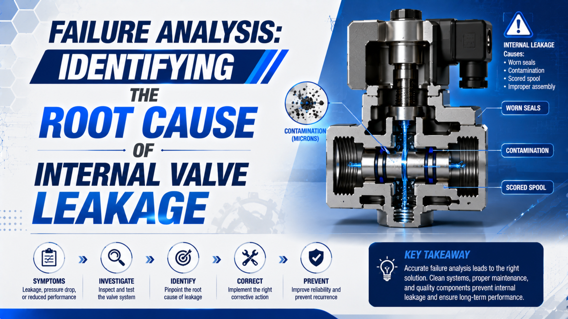
Internal valve leakage is air crossing a sealing boundary inside a valve when that path should be closed. The sound or flow at an exhaust port does not identify the failed component by itself. A defensible diagnosis records the commanded valve state, maps the possible port-to-port paths, separates the actuator from the valve, and compares measured flow with the exact product specification. That boundary matters because a leaking cylinder piston seal can send air back through a healthy 5-port valve. SMC documents this exact possibility for an SY5120 installation: air entering the cylinder’s B port can reach the valve’s EA exhaust through cylinder bypass (SMC 3/4/5 Port Solenoid Valve FAQ, accessed 2026).
Publisher and author information is available on About Us. Technical corrections and application questions can be submitted through Contact.
Key Takeaways
- Trace the port pair.
- Exhaust flow does not prove valve failure.
- Separate the actuator with a rated fixture before condemning the directional valve.
- Compare the measured path, pressure, temperature, valve state, units, and construction with the exact product specification; one VQC5000 metal-seal valve allows about 200 Ncc per port at 0.5 MPa.
Internal Leakage Is a Flow Path, Not Just a Hissing Sound
SMC states that one VQC5000 metal-seal valve can leak approximately 200 Ncc from each port at 0.5 MPa without being abnormal (SMC VQC5000V Operation Manual, 2016). The first diagnostic task is therefore to identify the actual flow path and the model-specific limit.
Port labels vary by manufacturer, but the common functions are consistent:
- 1 or P is the pressure-supply port.
- 2 or A and 4 or B are working ports connected to the actuator.
- 3 or R/EA and 5 or S/EB are exhaust ports.
- A separate pilot supply or pilot exhaust may exist on an externally piloted valve; trace both because the main stage can leak or remain between positions when either pilot path is wrong.
Internal leakage can cross several different boundaries. Supply-to-work leakage pressurizes an output that should be isolated. Work-to-exhaust leakage bleeds a cylinder chamber. Cross-port leakage transfers air between A and B. Pilot leakage may prevent the main spool or poppet from reaching its intended position. These faults need different evidence and often different replacement parts.
| Observation | Possible internal path | Competing explanation |
|---|---|---|
| Pressure rises at an inactive work port | P to A or P to B | wiring or pilot signal commands the wrong state |
| Continuous flow at EA or EB | work port to exhaust | cylinder piston bypass returns air through the valve |
| Both work-port pressures converge | A to B or two paths through the valve | actuator seal bypass or an external cross-connection |
| Valve shifts slowly and then leaks | pilot path or incomplete spool travel | low pilot pressure, restricted exhaust, or coil fault |
| Air appears around the manifold joint | gasket or static seal | loose fastener, damaged sub-base, or tubing leak |
Treat the valve as a network of boundaries, not as one sealed box. A pressure reading identifies which node changed. A measured flow identifies the severity. Only a controlled isolation test identifies which boundary the air crossed.
Why Can Exhaust-Port Leakage Point to the Cylinder?
SMC’s SY5120 troubleshooting example identifies 2 possible sources for air at the EA exhaust: the 5-port valve or internal leakage across the cylinder piston seal (SMC FAQ, accessed 2026). Replacing the valve before separating those paths can leave the original fault untouched.
Consider a double-acting cylinder with pressure applied to port A. If the piston seal bypasses, air can enter the B-side chamber. That air then follows the valve’s normal B-to-EB exhaust path. A technician standing at the manifold hears flow at EB, yet the directional valve may be routing air exactly as commanded.
Use three observations together:
- Verify the valve command and actual state.
- Record synchronized A- and B-port pressures plus cylinder position while the symptom repeats.
- Repeat the manufacturer-approved leakage test with the actuator separated, preserving the supply pressure, pilot state, temperature, valve position, and measurement method.
If exhaust flow stops when the actuator is replaced by a rated test fixture, the downstream circuit deserves attention. If flow remains through the same exhaust path with the actuator removed, the valve or manifold boundary becomes the stronger suspect. The test must preserve the same pressure, valve state, temperature, and measurement method.
The cylinder-drift isolation guide explains how synchronized pressure and position data distinguish movement from cause. Use the broader pneumatic-cylinder internal-leakage guide when the actuator remains suspect after separation.
Establish a Safe Test Boundary Before Touching the Valve
OSHA clause 29 CFR 1910.147(d)(5) requires potentially hazardous stored or residual energy to be relieved, disconnected, restrained, or otherwise rendered safe before servicing (OSHA 1910.147, accessed 2026). A valve-leakage test must control electrical commands, pilot air, trapped pressure, gravity, springs, and suspended loads.
Follow the machine’s approved energy-control procedure. Lock out every source that can re-energize the circuit, support hazardous loads mechanically, discharge trapped volumes through a verified safe path, and confirm isolation with appropriate instruments. A PLC output turned off or an emergency-stop button pressed is not automatically an energy-isolating device. Some diagnostic measurements require controlled pressure. That work belongs in a documented test procedure using rated fittings, guards, calibrated instruments, a defined exclusion zone, and personnel authorized for energized diagnostics. Do not improvise port plugs, loosen fittings under pressure, or disassemble a valve to “see where the air goes.”
ISO 4414:2010 covers significant hazards in pneumatic systems and includes design, installation, adjustment, maintenance, reliable operation, and energy efficiency within its scope (ISO 4414:2010, confirmed 2021). Use the machine risk assessment and the valve manufacturer’s instructions together; neither a generic blog procedure nor a single pressure reading replaces them.
Record the safe test boundary before starting:
- machine state
- permitted movement and restrained loads
- supply, pilot, exhaust, and downstream connections shown on the current circuit drawing
- complete valve part number, seal type, center condition, manifold station, and pilot arrangement
- pressure points and temperature measurement location
- test fixture ratings, caps, guards, isolation devices, instrument ranges, and calibration status
- authorized persons responsible for applying energy controls, performing energized diagnostics, verifying isolation, restoring the machine, and signing the test record after every person is clear
Which Isolation Tests Identify the Actual Leakage Path?
SMC lists 15 cm³/min or less as both internal and external leakage for its VQ20/30 dry-air valve family, while a VX2 catalog lists 1 or 15 cm³/min for different air-valve body constructions and defined conditions (SMC VQ20/30; SMC VX2). Isolation must retain the applicable test condition.
Begin with the least invasive evidence. Verify the supply pressure, command voltage, manual override, pilot pressure, and exhaust restriction. Mark the current tubing before changing anything. Check external joints separately with the approved external-leak method; a bubble at a fitting confirms an external leak, not an internal valve path.
Then separate one boundary at a time:
| Test boundary | What to hold constant | What the result can establish |
|---|---|---|
| Complete machine circuit | command, load, temperature, valve state | confirms the symptom is repeatable |
| Valve with actuator connected | A/B pressures, exhaust flow, position | maps the symptom to a work-port path |
| Valve with approved test fixture | supply, pilot, state, rated caps or sub-base | separates the valve from cylinder and downstream tubing |
| Actuator tested independently | load restraint, chamber pressure, position | tests piston or static seal bypass without the directional valve |
| Bench-tested valve | manufacturer fixture and acceptance method | quantifies a named port-to-port path against the product limit |
A pressure-decay test only proves that air left a known, isolated volume. It does not name the path. The volume, temperature, initial and final pressure, elapsed time, and every connected boundary must be controlled. The Pressure Decay Leak Rate Calculator can convert a valid decay test into estimated free-air flow, but it cannot distinguish a valve from a cylinder.
What Does Teardown Evidence Reveal About Root Cause?
An SMC VXZS troubleshooting chart separates internal leakage into 6 cause families: foreign matter, broken or worn parts, vibration or impact, fluid-related swelling, freezing, and piping conditions (SMC VXZS Operation Manual, accessed 2026). Teardown should test these hypotheses without destroying the evidence location.
Do not clean the valve before recording its as-found condition. Photograph the part number, ports, manifold position, fasteners, gaskets, spool orientation, seat, pilot passages, and deposits. Retain upstream filter residue when contamination is suspected. A particle on a bench has limited value if nobody can show where it was lodged.
| Evidence | Stronger root-cause hypothesis | What still needs confirmation |
|---|---|---|
| Particle imprint on a soft seat | contamination prevented full closure | particle material and upstream source |
| Axial scoring on spool or bore | abrasive wear or embedded debris | clearance, lubrication state, and matching residue |
| Swollen, soft, or cracked elastomer | media or cleaner incompatibility | seal material, chemical identity, temperature, exposure time |
| Cut O-ring at a manifold interface | installation damage or misalignment | groove condition, assembly method, tightening sequence |
| Clean valve that does not fully shift | pilot, coil, manual override, or exhaust problem | voltage and pilot pressure during the failed event |
| Rust, water, or sticky oil film | air-quality or compressor carryover problem | point-of-use particle, water, and oil measurements |
SMC’s VQC5000 manual identifies foreign material in the supplied air as a cause of increased internal leakage and directs users to replace the valve and clean the air supply. The same manual treats loose mounting, trapped gaskets, fitting damage, and manifold leakage as separate boundaries. That separation prevents every air-loss symptom from being labeled “worn seals.”
Use the valve-contamination failure-analysis guide to connect residue location with the affected spool land, valve seat, pilot restriction, or exhaust path. Particle size alone does not prove causation.
Compare Measurements with the Exact Valve Specification
Published SMC examples range from 1 cm³/min for one VX2 air-valve construction to about 200 Ncc per port at 0.5 MPa for a VQC5000 metal-seal design (SMC VX2; SMC VQC5000V). The difference shows why percentage-of-rated-flow rules are unreliable.
Before accepting or rejecting a valve, match every item below:
- model code
- option code and seal material
- spool, poppet, diaphragm, or metal-seal construction stated in the catalog
- commanded position, de-energized position, manual-override state, and pilot condition
- tested port pair and flow direction
- supply pressure, downstream pressure, and differential pressure at the measurement points
- ambient temperature and media temperature
- normalized-flow reference, such as ANR, plus the catalog’s stated reference conditions and unit basis
- new-product, endurance-test, or in-service acceptance condition together with instrument range, resolution, uncertainty, calibration status, stabilization time, and the date the reference specification was retrieved
The VX2 catalog states that its leakage values are taken at 20°C and, for the listed air version, at a defined pressure-differential range. Moving that number to another valve family, temperature, material, or test state discards the conditions that give it meaning. ISO 19973-2:2015 provides test procedures and reporting methods for pneumatic directional-control-valve reliability and specifies test equipment and threshold levels; the standard was confirmed again in 2026 (ISO 19973-2). It does not turn one supplier’s model limit into a universal maintenance threshold. Report the measured path in plain language: “P-to-A leakage with the valve de-energized,” “B-to-EB leakage in the commanded state,” or “external leakage at the manifold gasket.” A single entry labeled “valve leak” cannot be reproduced or compared after repair.
Correct the Cause, Then Verify the Same Test State
ISO 8573-1 classifies compressed-air purity across 3 primary contaminant groups: particles, water, and oil (ISO 8573-1:2010). One Festo directional valve datasheet, for example, specifies operating and pilot air to ISO 8573-1 class [7:4:4], demonstrating that required air quality belongs to the exact product and application (Festo valve datasheet, 2026).
Correction must address both the failed component and the condition that produced the failure:
| Confirmed cause | Corrective action | Verification evidence |
|---|---|---|
| Foreign matter at spool or seat | replace or service as permitted; correct filtration, piping debris, or ingress source | clean point-of-use sample and repeated path-specific leakage test |
| Swollen or chemically attacked seal | select a compatible valve and seal material; remove the incompatible medium | material record and stable leakage at operating temperature |
| Scored bore, damaged seat, or worn metal seal | replace the valve or approved internal assembly | as-left measured flow below the model limit |
| Insufficient pilot pressure or blocked pilot exhaust | restore pilot supply and exhaust capacity | full shifting under minimum operating condition |
| Damaged manifold gasket or assembly error | replace the gasket and assemble to the documented procedure | no external leakage at the interface |
| Cylinder piston bypass | repair or replace the actuator instead of the valve | valve-only test passes and cylinder-only test confirms repair |
Do not assign a universal filter grade. Check the valve’s air-quality requirement, point-of-use flow, allowable pressure drop, water control, oil policy, and contamination source. The ISO compressed-air quality guide explains why particle, water, and oil classes must be specified separately.
Verification should mirror the original failure state. Use the same valve position, port pair, pressure, temperature, dwell time, instrument, and downstream boundary. If the before-test measured B-to-EB flow and the after-test records only supply pressure, the repair has not been verified against the original evidence.
Keep a compact failure record with the part number, service hours or cycles if known, air-quality condition, symptom, measured leakage path, root-cause evidence, corrective action, and as-left result. This turns a replacement event into data that can reveal recurring contamination, assembly, or application problems.
Internal Valve Leakage FAQs: What Should Maintenance Teams Ask?
SMC’s VQC5000 manual treats approximately 200 Ncc per port at 0.5 MPa as normal for one metal-seal construction, while its VQ20/30 catalog lists 15 cm³/min or less (SMC VQC5000V; SMC VQ20/30). These answers therefore use model-specific limits and controlled boundaries.
Does airflow at an exhaust port prove the valve has failed?
No. SMC documents a 5-port circuit where cylinder piston bypass can send B-port air through the valve to EA. Verify the command and port pressures, then separate the actuator with the approved fixture. Persistent exhaust flow during a valve-only test is stronger evidence than sound at the assembled machine.
How much internal valve leakage is acceptable?
Use the exact model specification and its test condition. Published SMC examples include 1 cm³/min, 15 cm³/min, and about 200 Ncc per port for different constructions and conditions. A percentage of rated flow or one plant-wide pressure-decay limit cannot replace the product’s named port, pressure, temperature, and valve state.
Can a pressure-decay test identify internal valve leakage by itself?
No. Pressure decay shows that air left a known isolated volume. It cannot distinguish a valve path, cylinder bypass, fitting leak, or temperature-driven pressure change unless those competing boundaries are controlled. Convert decay to estimated flow only after recording volume, pressure basis, temperature, elapsed time, and every connected component.
Should a leaking pneumatic valve be repaired or replaced?
Follow the manufacturer’s service policy. Some valves have approved spool, seal, pilot, or gasket kits; others are replacement-only assemblies. Replace a scored bore, damaged seat, or unserviceable valve. Repair is defensible only when the leakage path is confirmed, approved parts and instructions exist, and the same acceptance test passes afterward.
How can contamination be confirmed as the root cause?
Link the residue to the failed feature. A particle imprint on the seat, directional scoring at a spool land, or debris blocking a pilot passage is stronger than a dirty filter alone. Preserve the location, compare upstream samples, identify the material when necessary, and repeat the path-specific leakage test after correcting the source.
Sources and technical references
- SMC, 3/4/5 Port Solenoid Valve FAQ: explains why exhaust-port flow can originate from cylinder internal leakage. Retrieved 2026-07-22.
- SMC, VQC5000V Operation Manual: product-specific metal-seal leakage, manifold faults, and contamination troubleshooting. Retrieved 2026-07-22.
- SMC, VQ20/30 Catalog: internal and external leakage limits for the named dry-air valve family. Retrieved 2026-07-22.
- SMC, VX2 Air Valve Catalog: construction-specific leakage rates and reference conditions. Retrieved 2026-07-22.
- SMC, VXZS Operation Manual: internal-leakage cause-and-countermeasure chart. Retrieved 2026-07-22.
- ISO 4414:2010, Pneumatic fluid power: General rules and safety requirements: pneumatic system safety and maintenance scope. Retrieved 2026-07-22.
- ISO 19973-2:2015, Assessment of component reliability by testing: Directional control valves: reliability test procedures, equipment, thresholds, and reporting. Retrieved 2026-07-22.
- ISO 8573-1:2010, Compressed air: Contaminants and purity classes: particle, water, and oil purity classification. Retrieved 2026-07-22.
- OSHA, 29 CFR 1910.147: control of hazardous energy and residual pneumatic pressure. Retrieved 2026-07-22.
- Festo, Air Solenoid Valve Datasheet 534560: model-specific operating and pilot-air class. Retrieved 2026-07-22.