

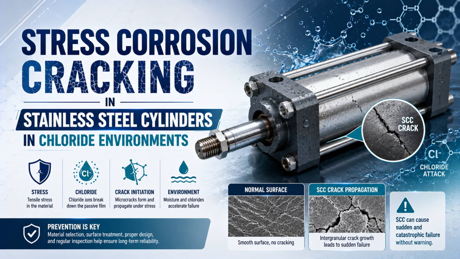
Stress corrosion cracking in a stainless steel pneumatic cylinder is possible only when a susceptible material, tensile stress, and a specific corrosive environment act together. Chlorides are a common trigger for austenitic grades such as 304 and 316, but chloride concentration or temperature alone cannot predict whether a cylinder will crack. SCC can produce narrow, branched cracks with little general metal loss, so a surface may look clean while a pressure-retaining or load-bearing feature is damaged. Yet a chloride stain, pit, pressure loss, or broken mount still does not prove SCC. Chloride stress corrosion cracking (ClSCC) is environment-assisted cracking at the point where tensile stress acts on susceptible material in a chloride-bearing local environment. It describes a mechanism, not the appearance of every crack found near salt.
SCC is location-specific.
Key Takeaways
- SCC needs three elements: a susceptible alloy, tensile stress, and a matching environment.
- The familiar 60°C value is a screening guide, not a universal safe limit.
- Liquid penetrant testing finds only discontinuities open to the examined surface.
- Suspected structural cracking calls for isolation and qualified failure analysis, not more cycling.
What Conditions Create SCC in a Stainless Steel Cylinder?
AMPP defines SCC as cracking caused by the combined influence of tensile stress and a corrosive environment. For a cylinder investigation, use a three-part screen: confirm a susceptible material condition, identify a credible tensile stress, and document the chemical environment at the actual crack location.
The three conditions overlap at a specific surface. They don’t have to describe the whole cylinder.
- Susceptible material condition: Record the exact alloy, product form, heat treatment, weld condition, cold work, surface finish, and any repair. A label such as “stainless” or “316” is not a complete material record.
- Tensile stress: Include pressure stress, assembly preload, bending from misalignment, thread-root stress, cold work, machining stress, weld residual stress, and thermal restraint. Compressive surface stress does not drive the crack in the same way.
- Specific environment: Identify chloride source, moisture, pH, temperature, oxygen availability, wet duration, evaporation, deposits, cleaner residues, and crevice geometry. Bulk-water chloride is only one input.
Pressure rating doesn’t settle the diagnosis.
Pressure is only one possible stress source. AMPP notes that forming, welding, heat treatment, machining, and grinding can introduce residual stress. A cylinder tube can therefore operate below its rated pressure while a cold-worked thread, weld, mounting feature, or constrained bracket carries the more important local tensile stress.
Crack morphology adds evidence, but it is not a standalone verdict. Chloride SCC in annealed austenitic stainless steel is commonly branched and transgranular. Sensitization or another material condition can promote intergranular cracking. A metallographic section and fracture-surface examination may be needed to distinguish the path from fatigue, overload, hydrogen-assisted cracking, or a crack that started at a corrosion pit.
The useful question isn’t “Was the cylinder near salt?” It is “Where did tensile stress and concentrated chloride share the same metal surface?” That change in wording directs inspection toward thread roots, weld heat-affected zones, cold-worked features, mounting interfaces, and deposit-covered crevices.
The 60°C and 50 ppm Myth
BSSA reports that chloride SCC is less common below 60°C, yet it has been observed at temperatures as low as 25°C. BSSA also warns that chloride has no universal concentration limit because evaporation and crevices can raise the local concentration far above the measured bulk environment.
Treat 60°C as a risk-screening landmark, not a pass-fail line. A fully immersed, near-neutral system behaves differently from a surface that is splashed, heated, allowed to dry, and splashed again. The second surface can concentrate a modest incoming chloride level into an aggressive deposit. The Nickel Institute’s fabrication guidance makes the same distinction. In near-neutral, fully immersed service, chloride SCC of 304 and 316 is rare below about 50°C. Wet-dry cycling, under-insulation conditions, and evaporation can produce cracking below that temperature because the surface chemistry no longer matches the bulk water analysis.
Bulk chemistry can hide the worst surface.
This is why a single ppm result cannot approve a cylinder. The laboratory needs to know what was sampled and where. Was it incoming rinse water, dried residue under a clamp, condensate behind an end cap, or contamination recovered from a crack mouth? Those are different measurements.
Use these variables together:
| Variable | Why it changes SCC risk | Evidence to record |
|---|---|---|
| Metal temperature | Changes electrochemical reaction and evaporation behavior | Stabilized surface temperature and short hot-cleaning peaks |
| Chloride source | Separates seawater aerosol, sanitizer, brine, process splash, and contaminated insulation | Product chemistry, water analysis, deposit analysis |
| Wet-dry cycle | Can concentrate salts that started at a low bulk concentration | Wash frequency, drying time, orientation, drainage |
| pH and oxidizing condition | Changes passive-film stability and localized corrosion | Cleaner recipe, residual chemicals, process contaminants |
| Crevices and deposits | Retain moisture and create a local chemistry | Mounting faces, threads, clamps, guards, labels |
| Stress state | Controls whether localized corrosion develops into cracking | Drawings, torque procedure, alignment, weld and forming history |
Measure the metal, not just the room.
The existing high-temperature pneumatic cylinder guide covers seals, grease, sensors, and thermal growth. Add the SCC review when heat coincides with chloride-bearing moisture and a susceptible stainless surface.
Where Do Chlorides and Tensile Stress Meet on a Cylinder?
A UK HSE alert documented chloride SCC in unpainted 316/316L pipe connectors where a swage ring carried tensile hoop stress in marine or saltwater-deluge exposure. HSE also warned that the connector crevice remained a possible initiation site and that painting did not guarantee elimination of the problem (HSE, 2015).
That alert concerns connectors rather than pneumatic cylinders, but the failure logic transfers: stressed geometry, retained chloride moisture, and susceptible metal shared one location. Start the cylinder inspection with the same interface-based approach.
The geometry held the clue.
External exposure zones
- Mounting faces and fastener seats: Wash water or salt aerosol can remain beneath brackets, washers, and clevis hardware. Misalignment adds bending stress.
- Threads and grooves: Thread roots, snap-ring grooves, and sharp changes in section raise local stress and can retain residue.
- Welds and cold-worked features: Residual stress and changed microstructure can coincide with poor drainage or heat.
- End-cap interfaces: Crevices, seals, and dissimilar hardware can hide deposits. Do not confuse adjacent galvanic damage with SCC.
- Rod and wiper region: The moving rod can carry contamination past the wiper, but scoring, pitting, seal wear, and bending remain competing explanations.
Internal exposure routes
Clean compressed air does not create chloride SCC by itself. An internal route becomes credible when chloride-bearing liquid or aerosol can enter through contaminated intake air, process backflow, failed cooling equipment, improper cleaning, or another cross-connection. Confirm the route before blaming air quality.
ISO 8573-1 particle, water, and oil classes do not define a chloride-ion class. If deposits are found internally, sample them rather than inferring chloride from rust color. Review condensate management and the compressed-air quality standard guide while keeping the chemical analysis separate.
Rust color isn’t a chloride analysis.
Similar damage that needs a different response
| Observation | SCC remains possible when | Main alternatives to test |
|---|---|---|
| Fine branched cracks | A susceptible alloy, tensile stress, and matching environment are documented | Fatigue, grinding cracks, thermal fatigue, hydrogen-assisted cracking |
| Pits beneath deposits | Cracks extend from or near pits under tensile stress | Pitting without SCC, crevice corrosion, chemical attack |
| Crack at a mixed-metal joint | Crack morphology fits SCC in the stainless member | Galvanic corrosion, fretting, bolt fatigue, coating failure |
| Pressure loss | A through-wall crack is confirmed | Rod seal, piston seal, fitting, tube, valve, or end-cap leakage |
| Broken mount or tie rod | Environment-assisted cracking is demonstrated | Overload, misalignment, vibration, corrosion fatigue |
Mechanism changes the corrective action.
Use the galvanic corrosion failure guide when dissimilar metals and a shared electrolyte are present. Use the tie-rod and mount fatigue guide when the fracture history follows cyclic loading, preload loss, or alignment error.
A Safe Failure-Investigation Workflow
OSHA 29 CFR 1910.147 requires hazardous stored or residual pneumatic energy to be relieved, disconnected, restrained, or otherwise rendered safe before servicing. A cylinder suspected of structural cracking should be isolated and removed under the site’s energy-control procedure before cleaning, pressure testing, or NDT.
Don’t cycle a suspect cylinder to “see if the leak gets worse.” A leak check can locate a pressure-loss path on equipment already judged safe to test, but it cannot identify the fracture mechanism.
Testing comes after energy control.
Preserve evidence before cleaning
Photograph the crack or leak location with the cylinder orientation and nearby wash direction. Record deposits, stains, coating damage, mounting position, fastener condition, temperature history, and chemical exposure. Retain loose deposits for analysis when the consequence justifies it. Protect fracture faces from rubbing and corrosion.
Cleaning everything to bare metal can erase the wet-path and chemistry evidence. On the other hand, NDT needs appropriate surface preparation. Let the investigator decide what to preserve, sample, and clean.
Match NDT to the flaw location
ASTM E165/E165M-23 states that liquid penetrant testing detects discontinuities open to the examined surface. It can reveal a surface-breaking crack on clean, nonporous stainless steel, but it cannot prove that an internal surface or subsurface region is crack-free.
That limit is important on a cylinder. A crack may begin under a mounting interface, inside a bore, at a weld root, or beneath a deposit. Geometry can restrict probe access. Tight cracks may contain corrosion product or process residue. The HSE connector alert notes that visual and penetrant inspection detect only surface-breaking cracks, while radiography identified internal cracks in that specific connector population.
No single method is automatically best:
| Method | Useful capability | Important boundary |
|---|---|---|
| Visual and magnified examination | Maps accessible surface condition, deposits, coating and crack pattern | Cannot clear hidden or internal surfaces |
| Liquid penetrant testing | Finds discontinuities open to a clean, nonporous examined surface | No subsurface detection; preparation and contamination matter |
| Eddy-current testing | Can detect surface and near-surface discontinuities in conductive material | Probe, frequency, geometry and reference standards control sensitivity |
| Ultrasonic testing | Can examine internal regions when geometry and crack orientation provide a usable sound path | Thin, curved, threaded or complex parts may be difficult |
| Radiographic testing | Can reveal selected internal features and changes in section | Planar crack orientation strongly affects detectability |
| Metallography and fractography | Can confirm crack path, origin and material condition | Usually destructive and needs qualified laboratory interpretation |
Coverage must match the suspected surface.
The inspection plan should be built backward from the suspected initiation surface. Choosing PT because it is inexpensive is weak logic when the likely crack begins on an inaccessible internal face.
Decide the population response
One confirmed SCC failure can indicate shared material, fabrication, mounting, or exposure conditions. Quarantine parts with the same heat, model, manufacturing route, location, cleaning history, or installation geometry according to consequence. Set the scope from evidence rather than assuming every stainless cylinder on the site is equally affected.
Which Stainless Steel Grades Reduce Chloride SCC Risk?
The Nickel Institute duplex fabrication guide says duplex stainless steels with at least 30% ferrite are far more resistant to chloride SCC than Types 304 or 316. The same guide warns that ferrite is susceptible to hydrogen embrittlement, so a duplex label is not a universal approval.
Choose the material as a finished cylinder assembly, not as a grade name. Product form, phase balance, weld procedure, heat treatment, cold work, surface condition, pressure rating, dimensional stability, seal interfaces, and supplier manufacturing capability all matter.
| Material family | Useful screening position | What still needs verification |
|---|---|---|
| 304/304L austenitic | Mild, controlled service where the full environment and temperature remain inside proven limits | Chloride concentration at the surface, wet-dry cycling, pH, stress, weld and cold-work condition |
| 316/316L austenitic | Better pitting resistance than 304 in many chloride exposures, but still susceptible to ClSCC | Do not treat molybdenum or low carbon as immunity; verify the actual service envelope |
| High-alloy austenitic, including 6% Mo families | Higher resistance can suit more aggressive chloride service | Exact alloy, fabrication route, availability, strength, joining and supplier data |
| Duplex 2205 family | Often a strong candidate where chloride SCC resistance and higher strength are needed | Phase balance, weld quality, product form, temperature, hydrogen or sour exposure, machining |
| Super duplex and nickel-rich alloys | Candidates when the environment exceeds lower alloy capability | Chemical-specific data, fabrication, cost, procurement, design code and finished-product qualification |
| Ferritic stainless families | High resistance to ordinary chloride SCC in some environments | General corrosion, toughness, forming, welding, product geometry and finished cylinder suitability |
A material family is only a shortlist.
The Nickel Institute process-engineering guidance identifies 2205 duplex, super austenitic grades such as UNS S31254 and N08367, and super duplex grades such as 2507 as candidates when conditions exceed 316. Candidate does not mean interchangeable.
Why not select by a ppm chart? Because published curves apply to named solutions, stresses, temperatures, oxygen contents, specimen types, and exposure times. Alleima’s SAF 2205 data describes constant-load specimens stressed to proof strength and separate calcium-chloride tests. Those results qualify the tested material and method, not every cylinder sold as 2205.
For food and hot washdown service, combine this material review with the stainless steel cylinder washdown guide. Cleanability, drainage, seals, grease, switches, fittings, and sanitation chemicals remain part of the assembly decision.
Prevention: Break One Part of the SCC System
HSE recommends corrosion prevention at the mechanical-design stage, including free drainage, fewer crevices, no dead spots, and access for cleaning and inspection (HSE materials guidance). For a cylinder, prevention should remove or control at least one necessary SCC condition and then verify that control in service.
Drainage is a material-control measure.
Control the environment at the surface
- Prevent chloride-bearing spray, condensate, cleaner, and process leakage from reaching the actuator where practical.
- Add shields or relocate the cylinder without creating an unventilated pocket that traps moisture.
- Orient mounts and guards for drainage. Seal only joints that can be sealed reliably and inspected.
- Define the cleaner identity, concentration, temperature, contact time, rinse, and drying step.
- Remove salt deposits with a validated procedure. Set frequency from measured accumulation and consequence, not a universal weekly schedule.
Coatings can help, but a coating is a maintained barrier rather than immunity. Edges, threads, fastener seats, damaged areas, and crevices need a compatible detail. HSE’s connector alert is a useful warning: painting may not eliminate risk when the geometry still retains chloride and stress.
Reduce avoidable tensile stress
Use the manufacturer’s mounting geometry and torque procedure. Correct misalignment, side load, thermal restraint, unsupported piping, and bracket distortion. Review cold work, weld procedure, machining, grinding, and repair history with the material supplier.
Do not prescribe a generic stress-relief temperature for an assembled cylinder. A heat treatment that helps one alloy or weld condition can damage another, distort precision features, alter duplex phase balance, affect sensitization, or destroy seals and finishes. Any thermal treatment belongs in the qualified manufacturing route.
Upgrade material with assembly evidence
Specify exact UNS or EN grades for all exposed pressure-retaining and load-bearing parts. Include weld filler, fasteners, rod, tube, end caps, mounts, coatings, and mating materials. Require a product-specific pressure rating and material traceability where consequence warrants it.
The change can expose another weak point. A stronger duplex tube doesn’t correct a chloride-trapping mount, incompatible fastener, damaged coating, or seal that fails in the cleaning chemistry. Review corrosion paths across the entire actuator and its corrosion-resistant fittings.
Build a risk-based inspection plan
Set the method and interval from consequence, susceptibility, accessibility, prior findings, exposure severity, and expected crack location. HSE’s thermowell alert calls for an inspection program based on susceptibility and consequence rather than a universal calendar (HSE, 2013).
Trigger an early review after a cleaner change, higher wash temperature, saltwater release, cooling-tower drift event, coating damage, mounting modification, unexplained leak, or SCC finding on a related asset. Document negative findings too. They help refine the susceptible population.
A prevention plan is stronger when every control maps to one side of the SCC triangle. Drainage and rinsing act on environment. Alignment and fabrication control act on tensile stress. Alloy selection acts on susceptibility. A measure with no clear mapping may be maintenance theater.
What Belongs in an SCC-Resistant Cylinder RFQ?
ASTM G36-24 uses boiling magnesium chloride at 155°C as an accelerated ranking method and warns that materials acceptable in hot chloride service may still crack in the test. An RFQ should therefore request service-relevant evidence, not a bare statement that an alloy passed one severe laboratory test.
ASTM G36 also says service correlation may not always be possible. ASTM G123-00(2022)e1 uses 25% sodium chloride acidified to pH 1.5 and states that acceptance criteria must be negotiated by the user and producer. Test names matter, but conditions and acceptance rules matter more.
Test severity is not service equivalence.
Send the supplier a complete exposure and loading envelope:
- Exact external and internal media, including chlorides, cleaners, sanitizers, process splash, aerosols, and contaminants
- Normal and peak cylinder-body temperature, hot-cleaning temperature, duration, frequency, and wet-dry cycle
- Pressure range, proof requirements, bore, stroke, speed, cycle rate, load direction, mounting, side load, vibration, and thermal restraint
- Required alloys, product forms, weld condition, heat treatment, surface finish, coating, fasteners, and material traceability
- Drainage orientation, crevices, guards, insulation, labels, clamps, and access for inspection
- Seal, lubricant, switch, fitting, tubing, wiper, and rod requirements under the same chemistry and temperature
- Applicable machine-safety, pressure, hygiene, plant, and jurisdiction requirements
- Inspection method, acceptance criteria, records, change notification, repair limits, and spare-part control
Ask what the evidence applies to. A coupon test may rank alloys. A weld qualification addresses a joint. A material certificate verifies composition and properties. A finished-cylinder pressure test checks pressure integrity at that time. None of these alone proves long-term SCC resistance in the installed environment.
Evidence always has a boundary.
For critical service, require a documented application review by the responsible plant engineer, materials specialist, cylinder manufacturer, and qualified NDT personnel. The purchasing decision should record residual uncertainty and the consequence-based inspection plan.
Stainless Steel Cylinder SCC FAQs
ASTM G36 tests stainless alloys in boiling magnesium chloride at 155°C, while ASTM G123 uses 25% acidified sodium chloride. Those two active methods alone show why no single chloride ppm or temperature number can approve a cylinder. The service environment and the test method must be evaluated together.
Can a 316 stainless steel cylinder develop SCC below 60°C?
Yes. Chloride SCC is less common at lower temperatures, but BSSA reports cases as low as 25°C. Wet-dry cycling, evaporation, deposits, crevices, pH, residual stress, and surface condition can make the local environment more severe than the bulk water analysis suggests. Treat 60°C as a screening landmark, not a guarantee.
Does a clean exterior rule out stress corrosion cracking?
No. SCC may produce narrow cracks with little general corrosion, and the initiation surface may sit beneath a mount, inside a bore, or under a deposit. A clean visible surface cannot clear inaccessible regions. Confirm the material, stress, exposure path, crack location, and suitable NDT coverage before reaching a conclusion.
Can dye penetrant testing prove that a cylinder is free of SCC?
No. ASTM E165/E165M states that penetrant testing detects discontinuities open to the examined surface. It does not inspect subsurface cracks or an inaccessible internal face. Surface preparation also affects the result. Choose PT, ET, UT, RT, or destructive laboratory work from the likely crack location and geometry.
Should a cracked stainless steel cylinder be welded and returned to service?
Not without an approved engineering disposition from the manufacturer and responsible plant authority. Welding changes residual stress, microstructure, dimensions, and the heat-affected zone. First isolate the cylinder, establish the failure mechanism and extent, review applicable repair rules, and correct the exposure path before any repaired or replacement unit returns to service.
Is duplex stainless steel always the best replacement for 316?
No. Duplex grades commonly provide much higher resistance to ordinary chloride SCC, but product form, phase balance, welding, machining, temperature, hydrogen exposure, seals, pressure rating, and supplier capability still matter. Select the complete cylinder against the service envelope instead of substituting a grade name into an unchanged design.