

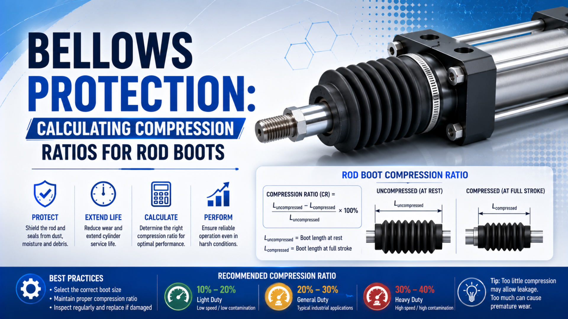
A rod boot compression ratio is the rated extended length divided by the rated retracted length. It is useful for comparing packaging efficiency, but it is not a universal pass-or-fail limit. A safe installation must fit between the supplier’s extension and compression ratings at both cylinder end positions without rubbing, bottoming, stretching, or trapping pressure.
That distinction matters. Cylinder stroke is only the change in piston position. Boot length is the changing distance between its two attachment planes, and those planes may include rod extensions, clevises, spacers, collars, flanges, or moving tooling. Measure the assembly instead of adding a generic allowance to the nominal stroke.
Key Takeaways
- Compression ratio describes packaging, not service life.
- Check rated extended and retracted lengths separately.
- Measure attachment planes at both cylinder end positions.
- Verify diameter, venting, alignment, material, speed, and environment before ordering.
What Does Bellows Compression Ratio Actually Mean?
Dynatect lists 12-inch sewn rod-boot sections with retracted lengths of 0.50 or 0.75 inch, depending on style. Those published dimensions correspond to section ratios of 24:1 or 16:1, well above a supposed universal 6:1 ceiling (Dynatect Gortite sewn bellows, accessed 2026).
For a supplier-rated boot, define the compression ratio as:
Here, is the dimensionless compression ratio, is the boot’s rated extended length, and is its rated retracted or collapsed length. Both lengths must use the same end reference. If the supplier excludes collars or flanges, exclude them from both measurements.
Compression ratio is a comparison of two rated lengths from the same boot construction. It does not measure protection efficiency, durability, material strain, or the force needed to move the cover.
The available axial travel is:
In this equation, is the boot’s rated travel. It is the length change the selected boot construction can accommodate between its published end limits. It is not automatically equal to cylinder stroke.
Available boot travel is the difference between the rated extended and retracted lengths. It remains a catalog boundary rather than a universal allowance.
Consider the two Dynatect sewn-boot examples:
| Published section data | Calculation | Section ratio | Available travel |
|---|---|---|---|
| 12 in extended, 0.75 in retracted | 12 divided by 0.75 | 16:1 | 11.25 in |
| 12 in extended, 0.50 in retracted | 12 divided by 0.50 | 24:1 | 11.50 in |
These values apply to specific sewn constructions. Molded elastomer, formed fabric, metal, and custom bellows can have very different convolution geometry, spring behavior, diameter, and end fittings. The ratio is therefore a catalog result, not a material constant.
The useful engineering question is not, “Is the ratio high enough?” Ask whether the installed boot remains inside its supplier-rated length envelope at every machine position. A large ratio can be perfectly normal for one sewn cover and impossible for another molded design.
The ratio also says nothing about outside diameter. Two boots with the same extended and retracted lengths may have different fold depths, wall constructions, collars, or reinforcements. The larger boot can interfere with a cylinder foot, sensor bracket, rod-end attachment, guard, or workpiece even though its axial calculation passes.
Which Dimensions Control a Rod Boot Fit?
ISO 15552 standardizes basic, mounting, and accessory dimensions for detachable-mount pneumatic cylinders from 32 to 320 mm bore at ratings up to 1,000 kPa. It does not standardize a protective boot envelope, so cylinder interchangeability does not guarantee boot clearance (ISO 15552:2018, confirmed 2025).
Start with the actual boot attachment planes. One plane is normally fixed near the cylinder head. The other moves with the rod end, clevis, coupling, or tooling. Record their separation with the cylinder fully retracted and fully extended:
Installed attachment distance is the measured separation between the same two boot mounting references at a defined machine position.
- : installed distance between boot attachment planes at full retraction;
- : installed distance between the same planes at full extension;
- : required boot travel, calculated from those two distances;
- : minimum clear boot inside diameter;
- : maximum outside diameter the machine envelope permits.
Required travel is:
For a straight axial installation, the two fundamental length checks are:
The first inequality prevents extending the boot beyond its rating. The second prevents compressing it below its rated collapsed length. Apply any reserve specified by the boot manufacturer to the appropriate limit; do not invent one percentage for every construction.
Diameter needs two separate checks. The inside diameter must clear the rod, rod-end thread, coupling, and any angular movement without rubbing. The outside diameter must clear surrounding hardware through the full stroke. Parker specifically tells buyers to compare boot outside diameter with the cylinder’s standard envelope dimension because foot-mounted cylinders can have critical interference (Parker Pneumatic Actuator Engineering Data, accessed 2026).
Do not assume the piston rod remains perfectly concentric with the boot. Rear-clevis and trunnion cylinders sweep through an angle. Rod-end joints move. Long horizontal covers sag. If the boot must accommodate shear, tilt, or lateral motion, give the supplier the maximum offset and angle as well as the axial distances.
How Do You Calculate Compression and Travel?
Parker publishes a model-specific rod-boot equation using a length factor of 0.13 plus a 1.125-inch allowance for the cited series. That calculation determines extra piston-rod length, not a universal boot ratio, and illustrates why a supplier formula must remain tied to its catalog (Parker engineering data, accessed 2026).
Use this sequence for a general geometry check:
- Move the machine to full retraction and measure between the intended attachment planes.
- Move it to full extension and measure between the same references.
- Calculate required travel .
- Obtain the candidate boot’s rated , , inside diameter, outside diameter, end dimensions, and motion restrictions.
- Check both end-position inequalities and radial clearance.
- Confirm speed, acceleration, orientation, venting, cycles, temperature, contaminants, and material compatibility with the supplier.
Travel utilization can be used as a comparison number:
Here, is the fraction of the boot’s published travel used by the machine. A result below one is necessary but not sufficient. It does not replace the separate retracted-length, extended-length, diameter, alignment, speed, or environmental checks.
Worked example: measuring the installed envelope
Assume a machine has these measured and supplier-rated values:
| Item | Illustrative value |
|---|---|
| Installed attachment distance at retraction | 90 mm |
| Installed attachment distance at extension | 390 mm |
| Candidate boot rated retracted length | 50 mm |
| Candidate boot rated extended length | 450 mm |
The machine requires:
The candidate boot provides:
Its travel utilization is:
At retraction, the installation stays 40 mm above the published collapsed length. At extension, it stays 60 mm below the published extended length. The axial geometry passes this illustrative screening, but final selection still needs the supplier’s required reserve, diameter, mounting, motion, environment, and cycle limits.
Worked example: applying a catalog-specific formula
For the Parker boot option cited above, the catalog calculation is:
Here, is the additional rod-end length, is stroke in inches, and is the published factor of 0.13 for the listed boot sizes. For a 300 mm stroke, convert the stroke to 11.81 inches before using the formula:
The result is approximately 67.6 mm of additional rod-end length for that catalog method. It is not the collapsed length of an arbitrary boot and should not be transferred to another manufacturer, construction, rod size, or mounting arrangement.
A ratio-only table hides the most expensive integration problem: a selected boot may have adequate travel but still require a longer rod end, move the coupling, reduce usable tooling clearance, or collide with a foot mount. Calculate the complete installed envelope before releasing the cylinder drawing.
If the longer rod end or boot mass changes the load geometry, review rod bending and support separately. The piston-rod deflection guide covers horizontal extension, while the rod buckling guide addresses compressive loading.
Rod Boot Failure Modes Beyond Compression Ratio
Mini-Flex states that its stock metal bellows are normally rated at 30% to 50% of maximum compression deflection (Mini-Flex Metal Bellows Design Guide, 2016). Movement beyond rated compression or extension can reduce cycle life and cause permanent deformation. Published motion limits therefore outrank a generic ratio.
A protective rod boot can pass the ratio calculation and still fail through one of these mechanisms:
| Failure mechanism | What the ratio misses | Evidence to inspect |
|---|---|---|
| Compression bottoming | Fold thickness, end hardware, internal guides, debris between folds | Shiny contact bands, crushed folds, rising end force |
| Overextension | Relaxed shape, seam load, tie-strip limit, material strain | Taut panels, opened seams, permanent set |
| Lateral rubbing | Sag, angular sweep, rod-end offset, nearby brackets | One-sided polish, holes, black wear debris |
| Pressure pumping | Enclosed volume changes faster than air can escape | Ballooning, inward collapse, delayed motion |
| Contaminant packing | Chips or slurry occupy fold valleys | Uneven stack height, hard deposits, local punctures |
| Thermal or chemical change | Compound stiffness, swelling, embrittlement, coating loss | Hardness change, cracking, tackiness, discoloration |
Venting deserves explicit treatment. Dynatect’s design guide asks how air enters and exits a cover and whether the bellows cycles under pressure or vacuum. Its accessories guide lists breather vents for sealed or fast-moving covers and wire guides for maintaining shape under pressure or vacuum (Dynatect enclosed-bellows RFQ, accessed 2026; bellows accessories, accessed 2026).
As a boot shortens, its internal free volume decreases. A blocked or undersized vent can raise internal pressure and make the folds balloon. During extension, restricted inflow can pull them inward. The exact pressure change depends on leakage, temperature, geometry, speed, and vent flow, so a simple compression ratio cannot predict it.
Long covers create another problem. Dynatect notes that internal guides help prevent snaking and twisting, while each guide requires roughly 0.75 to 1 inch of overall clearance depending on type. Tie strips can control expansion but increase required retracted length. These accessories change the same dimensions used in the ratio calculation.
The boot should not be used to carry side load or correct cylinder misalignment. A worn clevis, offset bracket, or unguided load can drag the cover against the rod and accelerate rod-bearing and seal wear. Check the side-loading guide before treating repeated boot damage as a material problem.
Material and Construction Selection
Dynatect offers 12 bellows construction methods and more than 500 stock molded bellows, which is why material names alone cannot define a compression ratio. Sewn, molded, folded, heat-sealed, vulcanized, wire-supported, and fabric-reinforced designs package differently even when they use related polymers (Dynatect bellows covers, accessed 2026; molded bellows, accessed 2026).
Choose construction first from the motion and contamination problem:
- Sewn coated-fabric covers can package into short retracted lengths and are adaptable to long travel. Seams, stitch exposure, guide requirements, and contaminant retention must be considered.
- Sealed fabric-reinforced bellows limit contaminant entry through seams and can resist spray, but trapped air needs a deliberate vent path.
- Molded elastomer boots provide formed collars and continuous walls. Their relaxed shape, convolution strain, tooling, and compound determine motion limits.
- Metal bellows suit selected temperature, vacuum, sealing, or pressure applications but have defined spring rate and deflection limits. They are not interchangeable with flexible dust covers.
Dynatect’s design guide connects specific material families with exposures: nitrile with hydrocarbon oils, PTFE with harsh chemicals, CSM with acids, polyurethane-coated fabrics with abrasion, and silicone-coated fiberglass with heat or sparks. These are screening directions, not blanket compatibility approvals.
| Service condition | Useful starting family | What still needs confirmation |
|---|---|---|
| Oil and grease | NBR or compatible coated fabric | Exact lubricant, temperature, swelling, seam system |
| Outdoor weather and UV | CR, CSM, EPDM, or qualified coated fabric | Ozone, sunlight, water, temperature cycling |
| Abrasive dust and chips | Polyurethane-coated or reinforced fabric | Cut resistance, fold cleaning, chip temperature |
| Weld spatter or radiant heat | Silicone-coated fiberglass, aluminized fabric, or purpose-built cover | Distance, peak temperature, flame requirement |
| Acids, cleaners, washdown | PTFE, CSM, FKM, EPDM, or qualified specialty compound | Concentration, time, pressure, sanitation requirement |
Trelleborg’s chemical guide shows why compound qualification matters. Its listed NBR families can span roughly -30°C to 100°C, FKM about -20°C to 200°C, and VMQ about -50°C to 175°C (Trelleborg Chemical Compatibility Guide, accessed 2026). These are material-family ranges, not a finished boot rating.
Temperature changes fold stiffness and the force needed to move the cover. Chemical absorption can swell a compound. UV and ozone can crack an unsuitable elastomer. Hot chips can penetrate a material that survives the ambient air temperature. Provide continuous temperature, intermittent peaks, exposure distance, chemical name, concentration, and cleaning method.
The cylinder seal material guide explains similar compound boundaries inside the actuator. Do not assume the boot and cylinder seals should use the same polymer: they see different mechanical strain, fluids, UV, abrasion, and heat sources.
For rod damage already in progress, inspect the surface before installing a cover. A boot prevents new contamination from landing directly on the rod, but it cannot repair chrome loss, corrosion pits, embedded chips, or a damaged wiper. Use the rod finish comparison and wiper-ring guide to separate surface, exclusion, and seal problems.
How Should You Install and Inspect a Rod Boot?
Parker’s boot instructions add calculated length beyond the normal rod-end dimension and require an outside-diameter clearance check. Those two published checks show why installation cannot begin with zip ties around an unchanged cylinder: the attachment geometry and surrounding envelope must be released together (Parker Pneumatic Actuator Engineering Data, accessed 2026).
Before installation:
- Clean the rod, wiper area, attachment surfaces, and nearby guards.
- Reject or repair a rod with burrs, sharp corrosion, weld spatter, or raised scoring that can cut the new boot.
- Confirm the boot part number, material, end style, orientation, vent location, and attachment dimensions.
- Move the machine through its full permitted geometry without the boot and verify radial clearance.
- Lock out the pneumatic and mechanical energy before fitting the cover.
During installation, keep the boot untwisted and concentric in its neutral position. Seat collars or flanges fully against their intended datums. Use the specified clamps, plates, fasteners, or retaining features. A clamp that is too loose can migrate; one that is too tight can cut a collar or block a vent.
Cycle the cylinder slowly after installation. Watch the complete boot, not only the ends. Folds should open and close in sequence without contacting the rod, bracket, foot, sensor, or workpiece. Stop if the cover snaps, balloons, pulls inward, twists, develops a hard fold, or increases resistance near either end.
In our experience with replacement reviews, the most revealing commissioning step is a slow full-stroke cycle viewed from more than one side. It exposes one-sided rubbing, hidden bracket interference, delayed venting, and fold reversal before production speed turns a small geometry error into a torn cover.
Commissioning record
Record a baseline that maintenance can compare later:
| Check | Record at commissioning |
|---|---|
| Boot identity | Manufacturer, part number, material, construction, revision |
| Geometry | Retracted and extended attachment distances, inside and outside clearances |
| Motion | Stroke, maximum speed, acceleration if relevant, cycles per day, orientation |
| Environment | Temperature, contaminant, liquid, UV, heat, cleaning method |
| Installation | Clamp or flange type, fastener setting, vent and guide arrangement |
| Condition | Photos at both end positions and any normal fold contact marks |
Inspection frequency should follow risk, not a universal monthly or yearly interval. A slow indoor fixture exposed only to dust does not need the same schedule as a welding cell, grinder, outdoor actuator, food washdown line, or high-cycle transfer machine.
At each inspection, check collars, clamps, seams, folds, vents, guides, and the entire circumference. Look for asymmetric wear, packed debris, pinholes, hardening, tackiness, discoloration, permanent stretch, and changes in the compressed stack. Inspect the rod and wiper where accessible.
Replace the boot when damage defeats exclusion, creates rubbing, restricts motion, or removes the required end-position reserve. Do not assign replacement life from material name alone. The supplier’s rated duty, observed condition, exposure, and machine risk determine the interval.
What Should Be Included in a Rod Boot RFQ?
Dynatect’s standard sewn-boot ordering process asks for five data groups: stock style, covered-part diameter, travel or extended length, end type, and mounting option. Its custom RFQ adds temperature, speed, acceleration, movements per day, pressure or vacuum, orientation, and contaminants (Dynatect sewn bellows, accessed 2026).
A build-ready request should include:
- Cylinder identity: manufacturer, series, bore, stroke, mounting, rod diameter, rod-end thread, and drawing.
- Attachment geometry: , , collar or flange reference planes, and permissible rod extension changes.
- Radial envelope: rod and coupling maximum diameter, available outside diameter, nearby brackets, and angular sweep.
- Motion: maximum speed, acceleration, cycle rate, dwell positions, orientation, and expected life target.
- Environment: contaminant size and type, chips, coolant, oil, washdown, chemical concentration, UV, moisture, and temperature.
- Pressure behavior: whether the cover is sealed, how it breathes, expected internal or external pressure, and vent restrictions.
- Construction details: material, reinforcement, seams, guides, tie strips, zipper, collars, flanges, clamps, and cleanability.
- Acceptance evidence: rated extended and retracted lengths, dimensional tolerances, material compatibility, inspection criteria, and installation instructions.
Do not submit only cylinder stroke and rod diameter. Those values cannot reveal the mounting-plane distance, collapsed space, outside interference, angular movement, or breathing requirement.
For a replacement boot, photos at both end positions are useful only when paired with dimensions and a reference scale. A picture can show rubbing or buckling, but it cannot establish the rated length, reserve, speed, material compatibility, or hidden interference behind a bracket.
If contamination repeatedly damages both the cover and the rod, reconsider the actuator architecture. A guided or rodless cylinder removes the projecting piston rod but introduces carriage, guide, and sealing-band protection requirements of its own. It is an engineering trade, not an automatic contamination cure.
For an application-specific review, provide the completed dimensional and operating record through the contact page. The About Us page describes the engineering and manufacturing scope behind that review.
FAQs: Rod Boot Compression Ratio Questions
The 12 legacy Dynatect sewn-boot styles list only two retracted lengths per 12-inch section, yet their inside and outside diameters vary across the range. That catalog pattern reinforces the five answers below: ratio is one geometry value, while diameter, construction, mounting, motion, and exposure complete the selection (Dynatect, accessed 2026).
Is a 3:1 to 6:1 compression ratio always correct for rod boots?
No. Dynatect publishes sewn rod-boot sections corresponding to approximately 16:1 and 24:1, while molded or metal bellows can have much lower ratios. Use the selected manufacturer’s rated extended and retracted lengths. A generic ratio cannot establish fold strain, compressed stack height, diameter, venting, or cycle capability.
How do I calculate a rod boot compression ratio?
Divide the supplier-rated extended length by the supplier-rated retracted length, using identical end references and units. Then subtract retracted length from extended length to find available travel. Finally, compare both installed attachment distances with their respective ratings; a ratio alone cannot prove that either end position fits.
Should cylinder stroke equal the boot’s available travel?
Not automatically. Cylinder stroke is piston travel, while boot travel is the change in distance between the two boot attachment planes. Rod extensions, clevises, spacers, moving brackets, angular mounts, or tooling can alter that relationship. Measure the attachment planes at full retraction and extension on the actual assembly.
Can a rod boot reduce cylinder force or speed?
Yes, if the boot is stretched, bottomed, unvented, misaligned, or too stiff for the temperature and speed. A correctly selected boot still has some spring and damping behavior, but the effect is construction-specific. Request force or speed limits when motion performance is sensitive, then verify them during commissioning.
Is a standard rod wiper enough without a bellows boot?
It depends on the contaminant. Parker notes that common cylinders already use a rod bearing surface and wiper, but recommends a collapsing cover where contaminants such as air-hardening paint can damage the exposed rod. A boot adds external exclusion; it does not replace the wiper, rod finish, seals, or alignment.
Sources and technical references
-
Dynatect Manufacturing. Gortite Sewn Bellows and Common Rod Boot Sizes. Stock section dimensions, mounting data, guides, and quote inputs. Retrieved July 23, 2026.
-
Dynatect Manufacturing. Bellows Design Guide. Materials, operating conditions, motion data, and RFQ requirements. Published 2019. Retrieved July 23, 2026.
-
Dynatect Manufacturing. Bellows Covers and Construction Methods. Construction, motion, material, and application options. Retrieved July 23, 2026.
-
Dynatect Manufacturing. Moulded Rubber Bellows. Stock range, materials, dimensions, and customization. Retrieved July 23, 2026.
-
Dynatect Manufacturing. Enclosed Bellows RFQ. Temperature, speed, acceleration, cycle, pressure, vacuum, venting, and contaminant inputs. Retrieved July 23, 2026.
-
Dynatect Manufacturing. Bellows Accessories and Mounting. Vents, guides, tie strips, collars, clamps, and plates. Retrieved July 23, 2026.
-
Parker Hannifin. Pneumatic Actuator Engineering Data: Rod End Boots. Boot length factor, extra rod-end length, and outside-diameter clearance. Retrieved July 23, 2026.
-
International Organization for Standardization. ISO 15552:2018. Pneumatic cylinder basic, mounting, and accessory dimensions for 32 to 320 mm bores and ratings up to 1,000 kPa. Confirmed 2025. Retrieved July 23, 2026.
-
Mini-Flex Corporation. Metal Bellows Design Guide. Construction-specific compression deflection, spring rate, and movement limits. Revision E, 2016. Retrieved July 23, 2026.
-
Trelleborg Sealing Solutions. Chemical Compatibility Guide. Elastomer family temperature and media screening data. Retrieved July 23, 2026.