

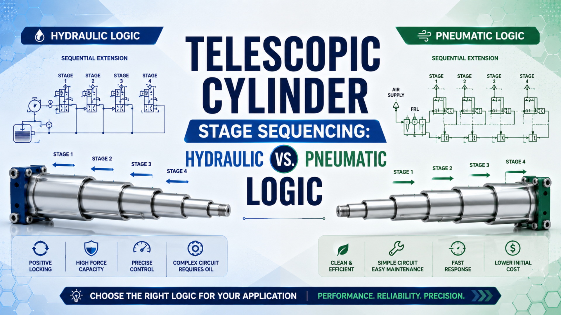
Common hydraulic telescopic cylinders normally extend from the largest moving stage to the smallest, while a pneumatic sequence must be defined by the actual actuator ports, effective areas, valves, stops, sensors, and load. Air compressibility matters, but it does not create one universal pneumatic failure pattern or prove that every pneumatic telescopic design needs the same control circuit.
Telescopic cylinder stage sequencing is the ordered transfer of motion from one moving stage to the next during extension or retraction. The required order comes from the selected cylinder’s construction and the machine control specification, not from the word “telescopic” alone.
Parker’s telescopic-cylinder design guidance describes the normal hydraulic extension order as largest stage first and the retraction order as smallest stage first. Its operating documentation also shows that each successive stage has a different effective area, so force decreases and speed increases as the cylinder transfers to smaller stages (Parker telescopic-cylinder design guide, accessed July 26, 2026).
Key Takeaways
- Confirm the manufacturer’s stage order before designing the circuit.
- Effective area, load, friction, backpressure, and internal stops determine hydraulic transfer.
- Pressure and elapsed time do not prove pneumatic stage completion.
- Mandatory sequence control needs stage confirmation, timeout handling, and fault testing.
In our experience, the fastest application review starts with one sequencing question: “What physical event authorizes the next stage?” A hard stop, a pressure threshold, a stage-position sensor, and a timer represent different evidence. Treating them as interchangeable is how a circuit appears correct on an unloaded bench and fails after installation.
What Sequence Is Normal in a Hydraulic Telescopic Cylinder?
Parker states that telescopic cylinders normally extend from the largest stage to the smallest, with the smallest stage retracting first. The largest moving sleeve carries the nested smaller stages until it reaches its stop; then the next stage begins. Special constructions can differ, so the product drawing and service instructions remain authoritative (Parker design guide, accessed July 26, 2026).
The common sequence is:
- The largest moving stage extends to its internal stop.
- Pressure and flow transfer to the next smaller effective area.
- Each smaller stage extends in turn.
- During powered retraction, the smallest stage normally returns first.
“Natural sequencing” describes an outcome produced by the cylinder’s internal geometry and load response. It does not mean the cylinder contains no engineered transfer features. Stop rings, seals, transfer passages, return paths, and the effective areas defined by those seals all contribute to the observed order.
Parker’s double-acting telescopic-cylinder instructions show pressure acting on the largest piston area until the first stop ring is reached. The next stage then moves, while oil trapped between sleeves returns through dedicated passages. That is a specific internal hydraulic architecture, not a rule that can be recreated by connecting any nested tubes to one valve (Parker double-acting telescopic-cylinder service manual, accessed July 26, 2026).
The stage labels also need care. Some drawings number the largest stage first; others number from the plunger or from the fixed barrel. An RFQ or control narrative should therefore use physical descriptions such as “largest moving sleeve,” “middle sleeve,” and “plunger,” plus drawing item numbers.
Hydraulic Stage Transfer: Effective Area, Force, and Flow
Parker identifies three familiar design relationships for telescopic cylinders: force depends on pressure and area, speed depends on flow divided by area, and cycle time depends on displaced volume and flow. Because every stage has a different effective area, each stage develops a different force and speed at the same nominal supply conditions (Parker design guide, accessed July 26, 2026).
A stage starts moving when its available actuator force exceeds the opposing load and resistance:
Here:
- is the pressure acting on stage ;
- is the effective area defined by the stage seals and porting;
- is the load reflected along the cylinder axis;
- includes seal, bearing, and alignment resistance; and
- represents opposing chamber pressure or return-line effects.
Effective area is the pressure-loaded area bounded by the active seals for a particular stage and direction. It may differ from the area calculated from the visible tube outside diameter.
The corresponding screening value for starting pressure is:
This equation explains why the largest effective area commonly moves first under a shared load. It also explains why sequence can change when a stage binds, a return path is restricted, the load geometry changes, or seal friction rises after contamination.
For a given incompressible-flow estimate, stage speed is:
where is stage velocity and is flow reaching that stage. As the cylinder transfers to a smaller effective area, velocity can increase even though the valve command and pump flow remain unchanged. At the same time, the available extension force decreases. The smallest stage therefore commonly sets the minimum extension-force capacity.
Don’t calculate every stage from visible tube outside diameter. Parker notes that the sealing boundaries determine the effective area, and a double-acting stage may use the inside diameter of the next larger stage. Use the manufacturer’s force table or section drawing when available.
For a broader fluid-power comparison, see hydraulic versus pneumatic system selection. That decision should follow the machine load, duty, environment, safety functions, and service capability, not the sequencing label alone.
Why Doesn’t Air Compressibility Define One Pneumatic Sequence?
Festo’s pneumatic courseware treats the extension order of parallel cylinders as a load-dependent behavior and uses directional and flow-control valves to demonstrate synchronization. That is a more defensible model than assuming all pneumatic stages move together or that friction will always select the same stage (Festo Pneumatics Fundamentals courseware, accessed July 26, 2026).
Compressed air stores energy as pressure and chamber volume change. A valve command begins a transient process:
- Supply air fills tubing, ports, and the connected chamber.
- Chamber pressure rises according to incoming mass flow, volume, leakage, and piston motion.
- The first stage to satisfy its force balance begins moving.
- Motion changes chamber volume and pressure, which alters the force available to every connected stage.
- Exhaust restriction and opposing pressure change acceleration and transfer timing.
This makes a pressure trace useful, but not self-explanatory. A pressure rise can indicate a stage reaching a stop, a mechanical bind, a closed valve, an undersized exhaust, or a sudden increase in load. The control system needs another piece of evidence before treating that pressure event as stage completion.
A pressure sequence valve is a pressure-operated valve that changes state when pilot pressure reaches its adjusted threshold. Festo lists an adjustable pilot range for one training valve and describes it as a spring-return poppet valve. That function detects pressure, not piston position (Festo pressure sequence valve, accessed July 26, 2026).
Pressure sequencing can be appropriate when load and resistance remain inside a validated window. It becomes fragile when:
- payload varies enough to shift starting pressure;
- orientation changes the gravity component;
- seal friction changes with temperature or wear;
- supply pressure falls during simultaneous plant demand;
- tubing or exhaust restriction changes;
- a stage contacts an external obstruction before its intended stop.
For more detail on stored-air behavior, read how air compressibility affects pneumatic cylinder control. The practical lesson is simple: use pressure as a measured process variable, not as automatic proof of position.
Pneumatic Architectures and Their Sequence Boundaries
Festo describes a common multi-position pneumatic cylinder as two separate cylinders connected together, with opposing piston rods and mechanically defined stops. Equal stroke lengths create three positions, while unequal strokes can create four. That architecture is not the same as a hydraulic-style nested telescopic cylinder (Festo multi-position cylinders, accessed July 26, 2026).
Use the construction, not the marketing phrase, to classify the actuator:
| Architecture | What moves? | How is sequence defined? | Main control concern |
|---|---|---|---|
| Single-port hydraulic telescopic cylinder | Nested sleeves | Internal areas, stops, seals, porting, and load | Confirm normal stage transfer and miss-staging limits |
| Double-acting hydraulic telescopic cylinder | Nested sleeves in both directions | Internal transfer paths and stage effective areas | Extension and retraction may use different areas |
| Purpose-built pneumatic telescopic actuator | Model-specific nested or staged members | Manufacturer-defined ports, locks, restrictions, or control modules | Never infer the circuit from appearance alone |
| Pneumatic multi-position or duplex assembly | Separate fixed-stroke cylinders | Valve-selected stroke combinations and hard stops | Command and confirm each discrete position |
| Servo-pneumatic axis | One controlled moving axis | Proportional valve, feedback, and controller | Tuning, settling, fault response, and holding |
If the application needs several fixed coordinates, the existing guide to multi-position cylinder intermediate stops covers that architecture in detail. If it needs arbitrary programmable positions, treat it as a motion-control problem rather than a telescopic sequencing problem.
A stage lock also has a specific job. It can prevent a later stage from moving until a mechanical release condition is met, but it must be documented for the load, direction, engagement state, release pressure, wear, and fault response. A generic rod lock should not be assumed to brake a moving stage; see the cylinder rod-lock safety guide.
Many sequencing disputes are terminology failures. One engineer means nested sleeves, another means back-to-back cylinders, and a supplier means a tandem force multiplier. A one-page section drawing with ports, effective areas, moving members, sensors, and stops resolves more ambiguity than a long control narrative built around the word “stage.”
How Should Valves and Sensors Enforce a Mandatory Sequence?
Parker’s pneumatic training material includes both pneumatic sequencing circuits and limit-valve exercises in which one cylinder’s motion must precede another. The transferable principle is event-based permission: the next output is enabled only after a defined completion signal, rather than after an assumed travel time (Parker Motion Control Training brochure, accessed July 26, 2026).
For a product with independently controllable stages, a basic PLC sequence can be written as states:
| State | Command | Required confirmation | Timeout response |
|---|---|---|---|
| S0: Home verified | All stage valves in defined home state | Every home sensor valid | Inhibit automatic start |
| S1: First stage moving | Energize only the authorized first-stage path | First-stage end sensor valid | Remove motion command and declare fault |
| S2: Second stage moving | Keep required hold state, then energize stage two | Second-stage end sensor valid | Remove motion command and declare fault |
| S3: Fully extended | Maintain only the documented holding state | Full-extension confirmation valid | Prevent process release or downstream motion |
| R1-R3: Retracting | Execute the documented reverse sequence | Each return sensor valid in order | Stop and retain diagnostic state |
Sensors should confirm physical states that matter. A piston switch may be sufficient for a noncritical sequence, but it doesn’t prove that a mechanical lock engaged, an external payload reached its datum, or an obstruction is absent. Safety-related confirmation may require independent sensing and a risk-assessed control architecture.
Timers still have a role. Use them as maximum-permitted transition monitors, debounce intervals, or diagnostic windows. Don’t use a fixed timer as the only evidence that a stage completed when load, pressure, flow, or temperature can change travel time.
Pressure switches can add diagnostic value:
- low pressure during motion can indicate supply loss or a large leak;
- pressure rising before the expected position can indicate obstruction or binding;
- no pressure rise after a confirmed stop can indicate leakage or a failed command;
- abnormal exhaust pressure can indicate a restricted silencer, valve, or return path.
The logic must define what happens after contradictory inputs. If an end sensor is already active before motion, or two mutually exclusive sensors are active together, automatic sequencing should not continue as though the state were trustworthy.
What Faults Should Commissioning Deliberately Test?
ISO 4413 and ISO 4414 address significant hazards in hydraulic and pneumatic fluid-power systems and apply to system design, installation, adjustment, operation, and maintenance. A sequencing test therefore needs more than a successful no-load cycle; it should challenge credible pressure, flow, sensor, load, and valve faults within a controlled validation plan (ISO 4413:2010; ISO 4414:2010, accessed July 26, 2026).
Begin with a documented baseline:
- Record the cylinder model, serial number, port map, stage diameters, stroke of each stage, sensor locations, valve part numbers, and software revision.
- Confirm mechanical alignment, external guidance, attachment geometry, and clearance throughout the full envelope.
- Run at reduced energy with no process load, then introduce the intended load and orientation.
- Capture supply pressure, stage or chamber pressure where available, valve commands, sensor transitions, and stage travel on one time base.
- Repeat at the allowed minimum and maximum point-of-use pressure and flow conditions.
Then test faults that the machine can encounter:
| Fault injection | What it reveals | Required observation |
|---|---|---|
| Delay or suppress a stage sensor in the test logic | Whether timeout prevents the next command | No unauthorized stage command |
| Simulate a sensor stuck active before motion | Whether contradictory states are detected | Start inhibited and diagnostic retained |
| Restrict exhaust within a controlled test range | Sensitivity to backpressure and silencer blockage | Transfer time and pressure remain inside acceptance limits |
| Reduce point-of-use supply pressure | Minimum operating margin | No skipped confirmation or uncontrolled recovery |
| Apply minimum and maximum rated test load | Load-dependent starting pressure and timing | Correct order across the declared envelope |
| Interrupt electrical power or control air | Defined de-energized behavior | Load and stages enter the risk-assessed state |
| Prevent a stage from reaching its stop using an engineered fixture | Obstruction response | Pressure or timeout fault occurs before the next stage is authorized |
Fault injection can create stored-energy and crush hazards. Use guarding, mechanical support, reduced pressure or flow, remote operation, and an approved test procedure. Never place a person in the movement envelope to create or clear a sequencing fault.
If a fault test exposes unstable speed, investigate valve and exhaust sizing rather than hiding the symptom with a longer timer. The quick-exhaust valve guide explains why exhaust placement can change cylinder response. Quick exhaust is not automatically a fix; it can also increase acceleration and impact energy.
What Should the Acceptance Record Contain?
ISO 10100:2020 defines acceptance testing for hydraulic cylinders, while ISO 4413 and ISO 4414 place reliability and safety in the context of the complete fluid-power system. A stage-sequencing acceptance record should therefore combine component identity, measured transitions, stated operating limits, and machine-level fault response rather than a single percentage called “sequencing reliability” (ISO 10100:2020, accessed July 26, 2026).
Record these items for every approved configuration:
- cylinder drawing revision and stage naming convention;
- normal extension and retraction order;
- valve, regulator, flow-control, silencer, hose, and fitting details;
- sensor type, switching location, expected state, and tolerance;
- point-of-use pressure during each stage, not only compressor-room pressure;
- transition time and total stroke time at minimum, nominal, and maximum load;
- pressure trace at normal transfer and at each injected fault;
- allowable overrun, dwell drift, and mechanical stop load;
- timeout thresholds and the basis for each threshold;
- de-energized valve state and load-support method;
- diagnostic code, reset conditions, and controlled recovery sequence;
- test temperature, lubrication condition, and supply-air quality;
- approver, date, software revision, and measurement calibration status.
Avoid a universal cycle count or pass percentage unless a documented reliability study supports it. A commissioning sample demonstrates the tested operating envelope and fault response. It does not prove lifetime performance under every future contamination, wear, maintenance, or payload condition.
A useful final question is: can a technician identify why the sequence stopped without cycling the machine again? If the answer is no, add state, pressure, sensor, and timeout diagnostics before production release. Troubleshooting by repeated motion can turn a detectable sequencing fault into mechanical damage.
For broader diagnostic methods, see common pneumatic cylinder fault isolation.
Telescopic Cylinder Stage Sequencing FAQs
Five specification questions prevent most sequencing misunderstandings: normal stage order, what pressure can prove, whether flow controls guarantee order, the difference between telescopic and multi-position construction, and the evidence required at acceptance. Parker, Festo, and ISO documentation all point back to model-specific construction and system-level validation rather than generic reliability percentages.
Do hydraulic telescopic cylinders always extend the largest stage first?
No. Parker describes largest-to-smallest extension as the normal arrangement, but special internal porting, unequal loads, double-acting construction, regeneration, or purpose-designed sequence features can change behavior. Use the selected model’s section drawing and service instructions. If the documented sequence and observed sequence differ, stop and diagnose the cylinder and circuit.
Can a pressure sequence valve prove that a stage is fully extended?
No. A pressure sequence valve proves that its pilot pressure crossed the adjusted switching threshold. That rise may follow a normal end stop, but it can also result from binding, an obstruction, excess load, or restricted exhaust. Use a position or lock-state confirmation when physical completion must authorize the next motion.
Can flow controls guarantee pneumatic stage order?
Flow controls can shape fill, exhaust, speed, and delay, but they do not independently prove stage position. Their result changes with pressure, load, valve flow, tubing, temperature, friction, and leakage. Use them inside a validated sequence, then add completion sensing and timeout handling when order is mandatory or a wrong transition creates risk.
Is a pneumatic multi-position cylinder the same as a telescopic cylinder?
Not necessarily. Festo’s common multi-position arrangement uses two separate cylinders connected together, with fixed stroke combinations creating three or four positions. A telescopic cylinder uses nested stages to obtain a long extended length from a shorter retracted package. Ask for a section drawing before selecting valves, sensors, or mounting hardware.
What should a stage-sequencing acceptance test record?
Record the actuator and valve identities, port map, stage order, load, orientation, point-of-use pressure, flow restrictions, sensor transitions, stage times, pressure traces, timeout behavior, power-loss response, and controlled recovery. Test the declared operating envelope plus credible faults. A successful unloaded cycle is useful evidence, but it is not complete acceptance.
Sources and technical references
- Parker, Designing With Cylinders: Telescopic Cylinders, normal extension and retraction sequence, effective-area selection, stage force, speed, and design limits. Retrieved July 26, 2026.
- Parker, Double Acting Telescopic Cylinder Service Manual, stop-ring transfer, stage effective area, return passages, and operating sequence. Retrieved July 26, 2026.
- Parker, Typical Sealing Systems in Common Fluid Power Devices, telescopic-cylinder sealing, stage speed, force changes, and contamination control. Retrieved July 26, 2026.
- Parker, Motion Control Training, pneumatic sequencing, limit-valve, directional-valve, and logic training scope. Retrieved July 26, 2026.
- Festo, Pneumatics Fundamentals Courseware, load-dependent parallel-cylinder sequence, series circuits, synchronization, and flow-control exercises. Retrieved July 26, 2026.
- Festo, Pressure Sequence Valve, pressure-threshold switching function and component documentation. Retrieved July 26, 2026.
- Festo, Multi-position Cylinders, back-to-back cylinder architecture and fixed-position combinations. Retrieved July 26, 2026.
- ISO 4413:2010, hydraulic fluid-power system rules and safety requirements. Retrieved July 26, 2026.
- ISO 4414:2010, pneumatic fluid-power system rules and safety requirements. Retrieved July 26, 2026.
- ISO 10100:2020, hydraulic-cylinder acceptance tests. Retrieved July 26, 2026.