

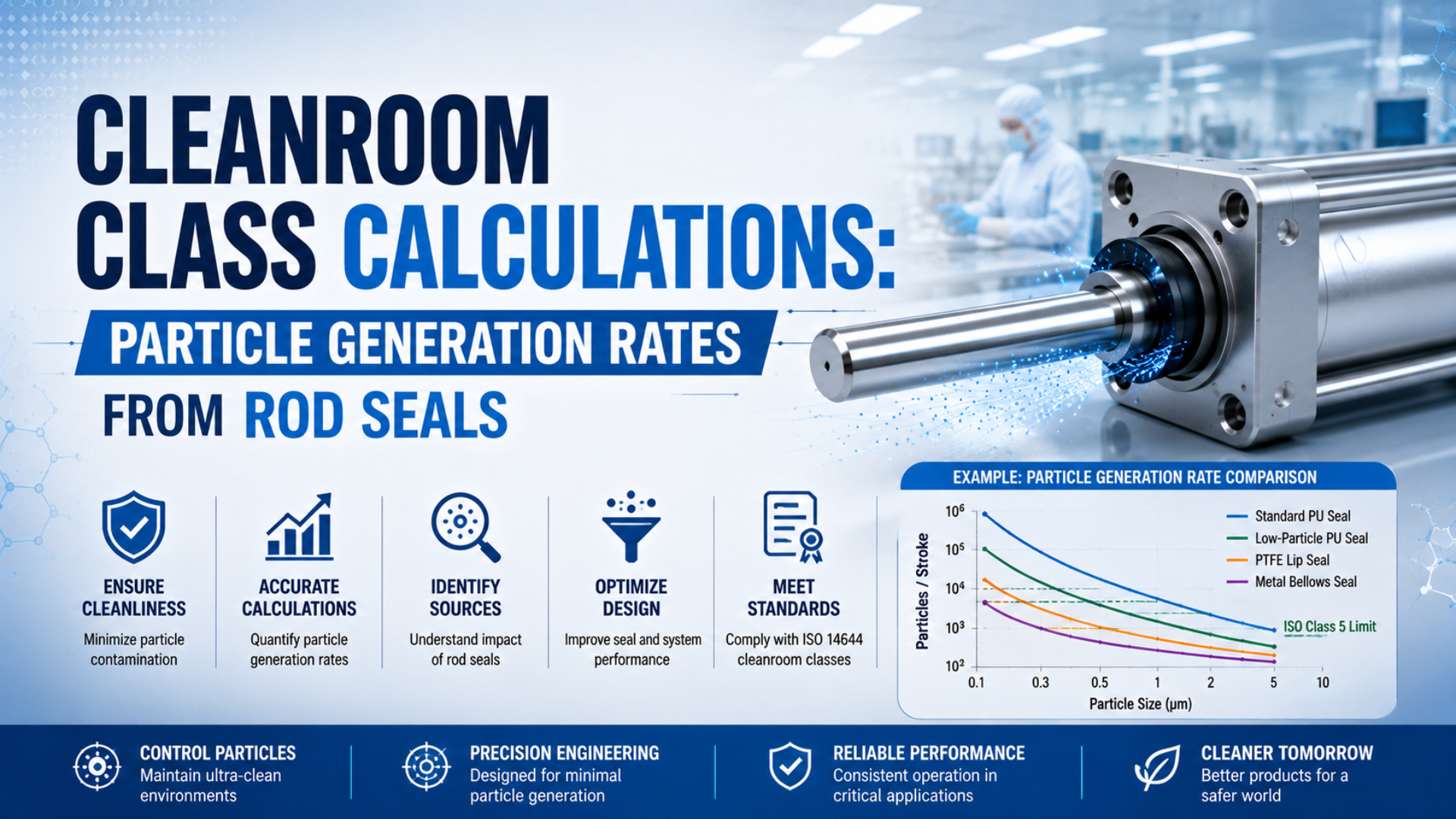
Particle generation rates from rod seals are background-corrected airborne particle counts attributed to seal motion over a stated time or cycle count. You can’t determine them from seal material, pressure, and stroke length alone. Measure the exact cylinder in a controlled setup, then retain the operating and sampling conditions with the result.
That distinction matters because an ISO cleanroom class is a concentration limit for air at designated locations. It isn’t a universal particles-per-stroke allowance for a cylinder. A component result becomes useful only when the test boundary and the installed cleanroom boundary are connected without hiding assumptions.
Key Takeaways
- ISO Class 5 permits 3,520 particles/m³ at 0.5 µm and larger (FDA, 2020).
- Calculate particles per cycle from background-corrected measurements, not theoretical seal wear.
- Keep sampled counts separate from total equipment emission.
- Confirm the installed room at designated locations and operating states.
The cleanest way to structure the problem is as an evidence chain. First measure what the actuator releases. Then model how that source could affect the surrounding air. Finally, classify or monitor the real clean zone. Each step answers a different question.
What Does an ISO Cleanroom Class Actually Measure?
ISO 14644-1 classifies air by cumulative concentrations at selected particle-size thresholds from 0.1 µm to 5 µm. At 0.5 µm and larger, ISO Class 5 permits 3,520 particles/m³, while ISO Class 6 permits 35,200 particles/m³ (ISO 14644-1, 2015; FDA, 2020).
The class applies to the measured cleanroom, clean zone, or separative device in a defined occupancy state. It does not assign one maximum particle count to each cylinder stroke. Nor does it identify whether a counted particle came from a rod seal, operator, garment, process material, guide rail, exhaust outlet, or another machine.
That prevents a common units error. Particles per cubic metre describe concentration. Particles per cycle describe a normalized equipment result. Particles per minute describe a source rate. You need a model or a controlled test to move between those quantities.
ISO 14644-14:2026 addresses the missing equipment step. It specifies a method for assessing machinery, components, tools, and measuring equipment for suitability by airborne particle concentration. Its scope covers sizes from 0.1 µm to 5 µm and larger, but it does not establish material selection, cleanability, biocontamination control, or process-specific performance (ISO 14644-14, 2026).
For the broader specification boundary, including materials, grease, suction and supplier documentation, see the guide to cleanroom pneumatic cylinder specifications.
Why Can’t Seal Wear Predict Particle Generation per Stroke?
ISO 21501-4 describes calibration and verification parameters for light-scattering airborne particle counters across a typical 0.1 µm to 10 µm range. Those parameters include counting efficiency, size-setting error, false count, sampling-flow error and sampling-time error (ISO 21501-4, 2018). Direct counting is necessary because wear mass alone doesn’t contain that information.
A mass-loss estimate cannot reveal how much worn material becomes airborne, how particles break up, which sizes cross the counter’s thresholds, or how many deposit inside the cylinder or test chamber. It also can’t separate rod-seal wear from wiper, bearing, grease, rod-surface, guide or surrounding-process particles.
Suppose a seal loses a known mass after a long test. Converting that mass into spheres requires an assumed material density and particle-size distribution. Real debris isn’t monodisperse or perfectly spherical. More importantly, only an unknown fraction reaches the sampled air. A calculated particle count would therefore be driven by assumptions rather than a measured source.
The same caution applies to published “typical particles per stroke” values. Without the complete part number, particle thresholds, background, probe location, airflow, speed, load, pressure, cycle count and data treatment, the number can’t be transferred to another cylinder. Use it as a lead for investigation, not a design constant.
Measuring Particle Generation Rates from Rod Seals
ISO 14644-14:2026 evaluates equipment suitability over particle sizes from 0.1 µm to 5 µm and larger, while ISO 21501-4 covers the counter characteristics used for clean-space measurements. A defensible cylinder test therefore records both the operating envelope and the measurement system instead of reporting one unexplained particles-per-stroke value.
Start with the exact test item. Record the manufacturer, full part number, bore, stroke, seal and wiper materials, grease, rod finish, guide arrangement, sensors, fittings and production revision. State whether the cylinder is new, run-in, aged, cleaned, relubricated or rebuilt.
Next, control the motion. At minimum, capture:
- mounting orientation, payload, side load and applied moment;
- supply pressure, speed, acceleration, deceleration and end cushioning;
- stroke length, cycles per minute, dwell time and total accumulated cycles;
- exhaust routing, vacuum or relief-port flow, and compressed-air quality;
- ambient airflow direction, velocity, temperature and relative humidity.
Then define the sampling system:
- counter manufacturer, model, calibration status and particle-size channels;
- sampling flow, sample duration or volume, dilution and coincidence controls;
- probe position, orientation and distance from the suspected release location;
- chamber or clean-zone geometry and the airflow path through it;
- background sequence, operating sequence, replicates and data acceptance rules.
Why so much detail? A probe moved a few centimetres can encounter a different local plume. A faster carriage can alter both mechanical wear and entrainment. The result belongs to that test envelope.
Festo describes a highest-particle-concentration method that uses a probe in laminar, isokinetic airflow and emphasizes that cleanroom suitability depends on installation position and operating parameters. It also assumes closed, monitored compressed-air systems without environmental exhaust leakage (Festo, accessed 2026).
How Do You Calculate a Background-Corrected Result?
ISO 21501-4 includes sampling-flow and sampling-time error among the counter parameters that affect number concentration. That is why operating and background samples must use the same size channel, volume, probe position and timing before their counts are subtracted (ISO 21501-4, 2018).
For equal-volume raw count samples, a simple background-corrected sampled count per cycle is:
Here, is the net number counted in particle-size channel per cycle, and are counts from equal sample volumes, and is the number of complete actuator cycles during the operating sample.
If the counter reports concentration rather than raw counts, use:
In this form, is particles per cubic metre and is the sampled air volume in cubic metres. The result still describes the particles that entered the counter’s sample stream per cycle.
That last boundary is easy to miss. Sampled particles per cycle are not automatically total particles emitted per cycle. Converting between them requires a validated chamber capture method, known airflow and mixing behaviour, or another documented transfer relationship. Don’t multiply a small sampled volume up to the full room volume unless the test method supports that extrapolation.
For an illustrative calculation, assume equal-volume samples produce 570 operating counts and 120 background counts while the cylinder completes 100 cycles. The net sampled result is 4.5 particles per cycle for that size threshold and setup. Report the replicate results and uncertainty; don’t silently round this into a universal emission factor.
If the test method produces a defensible total emission per cycle, the corresponding source rate is:
Here, is particles per minute in size channel , is validated emitted particles per cycle, and is complete cycles per minute. Keep extension and retraction separate when their release patterns differ.
Source-Rate Screening Against a Room Limit
ISO 14644-2 requires a monitoring plan based on parameters that measure or affect airborne particle concentration. It does not turn air changes per hour into a particle-removal count (ISO 14644-2, 2015). A source-rate calculation is therefore a screening model, not proof that an installed room passes classification.
For a well-mixed single-zone screening model:
Here, is the room concentration for size channel in particles per cubic metre, is the total internal source in particles per unit time, is room volume, is supply and exhaust flow, is supply-air concentration, and represents deposition or other first-order loss.
At steady state, the incremental concentration caused by the cylinder source is:
This relationship exposes the assumptions. It requires a source rate that represents total release into the zone, reasonably well-mixed air, stable flow and a suitable loss estimate. A unidirectional clean zone, local exhaust pickup, enclosure leak or near-product plume may behave very differently.
A sensible contamination budget also includes the existing room background and every simultaneous source. Could a low room-average increment hide a product-level problem? Yes. Local risk can be higher than the average when the actuator sits upstream of an exposed product.
What Are the ISO Limits at 0.5 µm?
At the 0.5 µm threshold, the maximum concentration rises by a factor of 10 for each whole ISO class: ISO 3 allows 35 particles/m³, ISO 4 allows 352, and ISO 5 allows 3,520 (FDA, 2020). These values must not be confused with the 0.1 µm column.
| ISO class | Maximum concentration at ≥0.5 µm |
|---|---|
| ISO 3 | 35 particles/m³ |
| ISO 4 | 352 particles/m³ |
| ISO 5 | 3,520 particles/m³ |
| ISO 6 | 35,200 particles/m³ |
| ISO 7 | 352,000 particles/m³ |
| ISO 8 | 3,520,000 particles/m³ |
The table is a room-air classification reference. It is not a table of allowable cylinder emissions. A cleanroom assessment still needs the designated sampling locations, minimum sample volume, operating state and statistical treatment required by the applicable procedure.
Legacy Federal Standard 209E labels such as “Class 100” are still heard in industry, but mixing them into an ISO table can hide unit and particle-size errors. Use the ISO class, particle threshold and particles-per-cubic-metre limit directly in specifications.
For a complete component-level selection workflow, including valves, tubing and exhaust treatment, use the Class 100 pneumatic component guide.
Which Cylinder Designs Can Reduce the Rod-Seal Source?
SMC reports that one CYP clean rodless-cylinder configuration reduced particle generation to 1/20 of its previous 12-CY3B series under stated test conditions. The catalog ties the result to a CYP32-200 cylinder, 5 kg workpiece, 200 mm/s average speed and data through 500,000 cycles, and says it isn’t guaranteed (SMC, accessed 2026).
This is the right way to read product data: as model-specific evidence with boundaries. It doesn’t prove that every magnetically coupled rodless cylinder is clean enough for every ISO class. It also doesn’t prove that a mechanically banded rodless cylinder, guided slide or electric actuator will behave the same way.
Consider each release path:
| Actuator approach | Particle-control opportunity | Evidence still needed |
|---|---|---|
| Standard rod cylinder | Low-wear wiper, controlled grease, smooth rod, bellows or extraction near the rod exit | Model-specific particle test with representative side load, speed and age |
| Cylinder with relief or vacuum suction | Captures particles near a dynamic seal before they enter the clean zone | Required suction flow, pressure effect, alarm strategy and failure-state test |
| Magnetically coupled rodless cylinder | Removes the exposed dynamic rod seal and can isolate the pressure chamber | External guide, carriage, grease, payload and lifetime particle data |
| Mechanically coupled rodless cylinder | Short package and configurable external guidance | Slot seal, sealing band, carriage, guide and exhaust release data |
| Cleanroom electric actuator | Sealed body, low-dust guide and optional extraction | Motor, brake, cable, belt or screw, grease and complete motion-profile data |
A bellows can contain one source but add folds, cleaning concerns and a new failure mode. Vacuum extraction can be effective, but only while flow is present and correctly routed. Design labels don’t replace evidence.
For mechanical differences, see the guide to rodless-cylinder sealing-band technology. For lubrication boundaries, compare the non-lube cylinder approach in cleanrooms.
What Must a Supplier’s Particle Report Include?
The SMC example publishes four conditions that materially limit proper interpretation: model, payload, average speed and a 500,000-cycle observation window. Festo adds installation position, operating parameters and highest-particle-concentration sampling to its cleanroom guidance (SMC, accessed 2026; Festo, accessed 2026).
Ask the supplier to identify:
- Hardware: complete part number, options, seals, wipers, grease, guides, sensors, fittings and revision.
- Operating envelope: pressure, stroke, speed, acceleration, load, side load, moment, orientation, cushioning, dwell and cycle rate.
- Lifecycle state: new, run-in and aged cycle counts, cleaning, relubrication, replacement parts and inspection findings.
- Air boundary: supply-air quality, exhaust routing, relief or suction flow, leakage assumptions and chamber airflow.
- Measurement system: counter, calibration, particle channels, sample flow and volume, probe geometry and maximum concentration control.
- Data treatment: background method, repeats, uncertainty, rejected runs, confidence limit and whether results are sampled counts, concentration, or total emission.
Reject a report that only says “ISO 5 compatible.” Ask which configuration was tested, where the probe was placed and what acceptance limit was applied. If the supplier reports a cleanliness class from a chamber test, confirm that the class statement follows the equipment-suitability method and does not imply blanket certification of every installation.
Compressed-air contamination and environmental particle release are separate boundaries. Specify particles, water and oil at the relevant point of use using the ISO 8573-1 compressed-air quality framework, then control exhaust so the air path doesn’t bypass the cleanliness strategy.
How Should Maintenance Affect the Calculation?
ISO 14644-2 covers monitoring plans for the 0.1 µm to 5 µm classification range and bases them on parameters that measure or affect airborne concentration (ISO 14644-2, 2015). It doesn’t prescribe one seal replacement interval, because wear depends on the actuator, load, speed, alignment, environment and service history.
Build the maintenance limit from evidence. Establish particle results for the accepted new or run-in state, then repeat the relevant measurement after a defined number of cycles or service time. Pair particle trends with leakage, rod condition, guide play, wiper condition, speed and pressure data.
Trigger reassessment after:
- seal, wiper, grease, guide, rod, carriage or sealing-band replacement;
- changes to speed, acceleration, payload, side load, mounting or cushioning;
- altered suction, exhaust, supply-air treatment or surrounding airflow;
- cleaning-agent, temperature or humidity changes;
- particle excursions, abnormal leakage, sticking, scoring or visible debris.
Don’t wait for a generic cycle number if the counter shows a sustained change. Conversely, don’t replace a seal every three months without data showing that interval controls the actual risk. The maintenance plan should preserve a measured state, not repeat an inherited rule.
The rodless-cylinder preventive maintenance checklist provides the mechanical checks that should accompany particle trending.
Conclusion
ISO Class 5’s 3,520 particles/m³ limit at 0.5 µm describes air concentration, not a universal rod-seal allowance (FDA, 2020). Calculate background-corrected sampled counts first, convert them to total emission only with a validated method, and verify the installed clean zone separately.
The practical sequence is short: identify the exact actuator, test it under representative and worst credible conditions, preserve the sampling boundary, normalize the result honestly, screen room impact with stated assumptions, and confirm the real machine in its required operating state.
That approach may produce a less dramatic number than a theoretical wear calculation. It produces a much more useful decision.
Rod-Seal Particle Generation FAQs
ISO 14644-14:2026 assesses equipment suitability for particle sizes from 0.1 µm to 5 µm and larger, while ISO 14644-1 classifies air at designated locations (ISO, 2026). The answers below keep component measurements, engineering estimates and room classification in their proper roles.
Can rod-seal particle generation be calculated from seal wear?
Not reliably. Wear mass does not determine particle-size distribution, airborne fraction, deposition or the share captured by a counter. Measure operating and background samples with the same setup, then normalize the net result by completed cycles. Use mass-loss data as supporting wear evidence, not as a substitute for airborne particle counting.
What is the correct ISO Class 5 limit at 0.5 µm?
The maximum concentration is 3,520 particles/m³ for particles 0.5 µm and larger. The value is a room-air classification limit, not an allowable emission rate per cylinder. Classification must follow the required sampling locations, sample volumes, occupancy state and data treatment.
Are sampled particles per cycle the same as total emitted particles per cycle?
No. A particle counter measures only the air entering its sample inlet. Converting sampled counts into total equipment emission requires a validated chamber or airflow method that relates the sample stream to the complete release. Without that relationship, label the result as net sampled particles per cycle.
Is a rodless cylinder automatically suitable for ISO Class 5?
No. Removing an exposed rod seal can eliminate one particle source, but guides, carriages, sealing bands, grease and connected equipment can still release particles. Suitability must be supported by model-specific data for the installation position, payload, speed, lifecycle state, airflow and particle thresholds.
When should a cleanroom cylinder particle test be repeated?
Repeat or reassess the test after changes to seals, grease, guides, mounting, payload, speed, suction, exhaust, cleaning chemistry or nearby airflow. Particle excursions, abnormal leakage, scoring, sticking and visible debris are also triggers. Set routine intervals from measured ageing data rather than a universal month or cycle limit.
Sources and technical references
- ISO 14644-1:2015, classification of air cleanliness by particle concentration. Retrieved 2026-07-26.
- ISO 14644-2:2015, monitoring to provide evidence of cleanroom performance. Retrieved 2026-07-26.
- ISO 14644-14:2026, equipment suitability by airborne particle concentration. Retrieved 2026-07-26.
- ISO 21501-4:2018, calibration and verification of light-scattering airborne particle counters. Retrieved 2026-07-26.
- FDA compounding guidance, ISO class limits at 0.5 µm and larger. Retrieved 2026-07-26.
- Festo cleanroom guidance, highest-particle-concentration method and application boundaries. Retrieved 2026-07-26.
- SMC CYP clean rodless-cylinder catalog, model-specific particle data, test conditions and limitations. Retrieved 2026-07-26.