

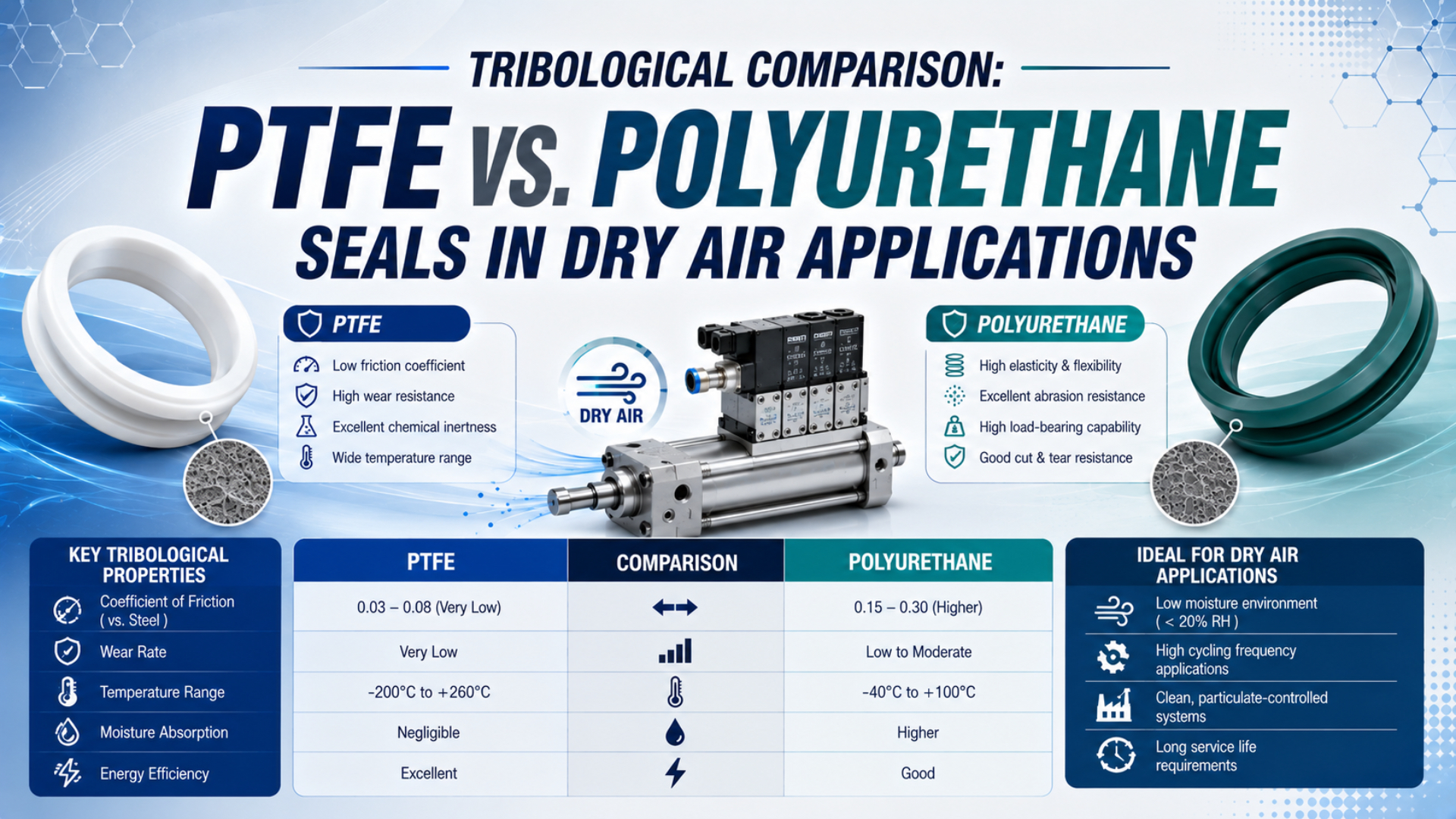
PTFE-based and polyurethane seals can both work in dry pneumatic service, but neither material family wins every application. For PTFE vs. polyurethane seals in dry air, PTFE-based designs are often considered when low breakaway force, stick-slip control, chemical resistance, or a wider temperature capability matters. Pneumatic polyurethane designs often bring elastic recovery, abrasion resistance, compact profiles, and economical replacement. Correct selection starts with the finished seal. Compound, filler, profile, energizer, lip preload, counterface, grease, pressure, speed, temperature, dwell, air quality, and acceptable leakage all change the result, so an incomplete comparison can look precise while pointing to the wrong seal.
Key Takeaways
- ISO 8573-1 separates particles, water, and oil into 3 air-quality categories.
- A published friction coefficient cannot predict cylinder breakaway force by itself.
- Polyurethane pneumatic seals can be qualified for dry air.
- Compare exact seal designs under representative pressure, speed, surface, dwell, and temperature.
Start by Defining Dry Air
ISO 8573-1:2010 controls three independent compressed-air contaminant groups: particles, water, and oil (ISO 8573-1, accessed 2026). Meaningful seal comparison starts only after the point-of-use specification states its water condition, oil limit, particle limit, and measurement location. “Dry” alone does not define cleanliness or lubrication.
Dry air is compressed air with water content controlled to a stated limit at a stated measurement point. Use a pressure dew point or water class.
For pneumatic seal selection, document the pressure dew point or required water class at the point of use. Then record the oil and particle classes separately. Air that is very dry may still contain compressor oil or solid contamination, while oil-free air may still carry enough moisture to affect corrosion, grease, or process quality.
These terms answer different questions:
| Term | What it should mean in an engineering specification | What it does not prove |
|---|---|---|
| Dry air | Water content or pressure dew point is controlled | The air is particle-free or oil-free |
| Oil-free air | Oil concentration meets a stated limit | The cylinder contains no assembly grease |
| Non-lube operation | No routine airline oil is added during service | Sliding interfaces have no lubricant film |
| Clean air | Particles are controlled to an agreed class | Water and oil meet the process requirement |
| Dry-running test | A defined test runs without added lubricant | Every production seal will survive the same duty |
This distinction prevents a common maintenance error. A non-lube cylinder often contains grease applied during assembly, even though no lubricator feeds oil mist into the airline. The air lubrication and seal-material guide explains why changing that lubrication regime requires approval for the complete cylinder. The self-lubricating seal guide explains how factory grease supports non-lube operation. Parker’s OSP-P provides one model-specific example: it specifies permanent grease and says added oil mist is unnecessary. If oil mist is introduced, the supply must remain constant (Parker OSP-P operating instructions, accessed 2026). None of those instructions describe an unlubricated seal.
Why Can’t a Published Friction Coefficient Select a Seal?
Parker uses ASTM D3702 for dry-running evaluations. The method records three time-dependent outputs: wear, coefficient of friction, and running temperature (Parker PTFE material data, accessed 2026). Reported values belong to the defined specimen and counterface under fixed roughness, load, speed, and duration, not to every pneumatic cylinder.
Breakaway force is the force required to initiate motion after the actuator has remained stationary for a defined dwell. It is not a material coefficient. Record it at stated pressure, temperature, dwell, direction, load, and surface condition.
Material coupons sliding on steel are not pressurized seal lips inside an actuator. Cylinder breakaway force includes the seal’s contact condition and pressure response. Guide friction, alignment, side load, and every dynamic surface add their own effects. Running friction can then change as the seal heats or wears in. Transfer-film development adds another variable. Those interactions are why material-level ranges cannot support a statement such as “PTFE is 0.04 while polyurethane is 0.5.” Even valid values may describe different tests or surfaces, and Parker notes that its tribometer result differs from the static coefficient measured with another standard method.
The practical measurements are component-level results:
- Breakaway force after several defined dwell periods, temperatures, pressure states, and cold starts
- Bidirectional running force
- Low-speed stick-slip, velocity trace, position stability, and reversal behavior across the complete working stroke
- Leakage at minimum pressure and at the maximum approved test pressure
- Stabilized seal and counterface temperature
- Wear, debris, leakage trend, coating damage, lip deformation, counterface scoring, and surface condition after a defined travel or cycle count
The dynamic versus static cylinder seal guide helps separate sliding interfaces from stationary joints before friction or wear data is interpreted.
Where PTFE-Based Seals Have an Advantage
Parker separates its PTFE sealing portfolio into seven material series, ranging from virgin or mineral-filled formulations through glass, carbon, metal, polymeric-filled, and modified PTFE (Parker PTFE material data, accessed 2026). That range explains why “PTFE” is too broad for selection: filler and processing change wear, creep, conductivity, and counterface behavior.
A PTFE-based seal is a finished design that places a specified PTFE compound at its sliding interface. Other elements can still set the operating limit, including the spring, elastomer energizer, backup, adhesive, assembly lubricant, neighboring seal, groove geometry, and adjacent hardware.
PTFE-based sealing surfaces are strong candidates when an application needs low stick-slip, chemical resistance at the exposed lip, or a qualified temperature capability beyond common elastomer limits. Spring-energized or elastomer-energized profiles can maintain contact because PTFE itself has limited elastic recovery compared with polyurethane. Those constructions also introduce design tradeoffs:
| PTFE-based characteristic | Potential benefit | Qualification question |
|---|---|---|
| Low-friction sliding surface | Lower breakaway or smoother low-speed motion in a suitable design | Which compound, profile, preload, surface, pressure, and dwell produced the result? |
| Broad chemical resistance | Useful when the exposed PTFE surface contacts aggressive media | Is an elastomer energizer, backup, adhesive, or lubricant also exposed? |
| Filled formulations | Fillers can improve wear, deformation resistance, or heat transfer | Is the filler compatible with the counterface material and hardness? |
| Transfer-film behavior | A stable film can reduce friction and wear | Can the surface develop and retain the required film under short strokes or reversals? |
| Low elastic recovery | Predictable sliding material when properly energized | Does the profile maintain sealing contact through wear, tolerance, and thermal change? |
Virgin PTFE is not a default high-pressure or high-speed solution. Parker identifies deformation under load as a limitation, which is why seal designers use fillers to improve selected properties; however, some fibrous fillers can abrade soft counterfaces, so the compound and hardware finish need approval as one tribological pair. Chemical resistance needs the same discipline. Parker notes that a PTFE backup ring does not protect an untreated elastomer O-ring from chemical exposure. The PTFE surface may survive while an energizer, adhesive, grease, or neighboring seal sets the operating limit (Parker PTFE FAQs, accessed 2026).
For elevated temperatures, start with the complete cylinder rating rather than the polymer’s headline range. The high-temperature pneumatic cylinder guide covers grease, magnets, sensors, cushions, guides, and dimensional change that can set a lower limit than the sealing surface.
Where Polyurethane Seals Have an Advantage
Trelleborg recommends pneumatic piston seals made from Zurcon polyurethane and FKM for cylinders running with dry air (Trelleborg pneumatic piston seals, accessed 2026). This product range is a second practical manufacturer example. Properly formulated polyurethane pneumatic seals are not automatically disqualified by low moisture or the absence of oil mist.
Pneumatic polyurethane can provide elastic recovery and strong wear resistance. Many grades also resist abrasion and tearing. These properties suit compact molded lips that must follow bore tolerances and recover after deformation. The same lip may need to scrape contamination or resist extrusion. Trelleborg offers optimized polyurethane and PTFE-based materials in its pneumatic range (Trelleborg pneumatic seals, accessed 2026). Profile and compound are therefore selected as one system. Exact identification still matters. Family names do not disclose formulation or hardness, and they omit temperature capability, grease compatibility, dynamic friction, and breakaway after a long dwell.
Polyurethane is often worth screening first when:
- Elastic recovery
- Abrasive contamination or demanding scraping duty is expected at the lip, guide interface, and exposed counterface during the complete maintenance interval
- The cylinder already has a compact molded profile qualified for its groove and assembly process
- Counterface hardness, coating thickness, or durability rules out the proposed abrasive PTFE filler
- Replacement cost matters, but only after model-specific leakage, friction, wear, maintenance, and reliability evidence is available
Price misleads. Lower purchase cost has no value if leakage or maintenance demand rises. A qualified polyurethane profile can outperform an unsuitable PTFE construction in the same dry-air system.
The industrial cylinder seal-type guide distinguishes piston and rod seals from wipers as well as cushion and static seals because one material may fit one position but fail another.
PTFE vs. Polyurethane in Dry Air: A Conditional Selection Matrix
According to Parker and Trelleborg, PTFE selection needs actual-service or representative testing while both polyurethane and PTFE-based pneumatic materials remain available. Together these sources support one practical rule. Start with the failure risk and acceptance limits instead of a generic material ranking.
Use the following matrix to screen candidates, then confirm the result with the exact product datasheet and a representative test.
| Application priority | PTFE-based design | Polyurethane design | Evidence needed before release |
|---|---|---|---|
| Low breakaway after dwell | Strong candidate when profile and preload are controlled | Possible with a qualified low-friction pneumatic profile | Breakaway at defined dwell, pressure, temperature, and surface condition |
| Low-speed stick-slip control | Strong candidate when transfer film and counterface are stable | Application-dependent | Speed trace, position stability, running force, and repeatability |
| Abrasion and scraping | Depends on filler, profile, and contaminant | Often a strong candidate | Contaminant test, lip inspection, debris, and leakage trend |
| Aggressive chemical exposure | PTFE surface may be advantageous | Highly formulation-dependent | Compatibility of every exposed seal component, grease, and hardware |
| Soft aluminum counterface | Avoid unqualified abrasive fillers | May be suitable with the specified finish | Counterface hardness, coating durability, roughness, and wear inspection |
| High pressure or speed | Not an automatic choice because creep and heat remain concerns | Not an automatic rejection | Exact pressure-speed-temperature rating and representative endurance test |
| Very dry, no added oil mist | Possible when the finished design is qualified | Possible when the finished design is qualified | Factory grease rule, air classes, friction, leakage, wear, and restart behavior |
| Lowest verified ownership cost | Depends on evidence from the installed duty | Depends on evidence from the installed duty | Purchase, seal kit, labor, downtime, travel, leakage, and replacement record |
How Should You Validate the Seal Before Release?
Parker prefers actual-service testing for PTFE. Otherwise the test should simulate operating conditions as closely as practical (Parker PTFE material data, accessed 2026). Useful pneumatic validation records at least six condition groups covering identity and air quality plus motion and load plus surface and acceptance criteria.
Start with the failure.
Precision positioning needs breakaway and stick-slip evidence. A high-cycle transfer line needs leakage and wear trends while a clean process adds limits for particles, grease, and exhaust contamination.
-
Freeze the candidate identity. Record the supplier, complete seal designation, compound, filler, hardness, profile, energizer, production batch, installation method, and approved grease. “PTFE” or “PU” is not enough.
-
Freeze the hardware. Record groove dimensions, bore or rod material, coating, hardness, surface finish, guide arrangement, alignment, and any damage. A different counterface creates a different tribological system.
-
Reproduce the air and environment. Control pressure, pressure dew point, oil, particles, temperature, chemicals, cleaning agents, and planned lubrication regime. Test cold starts and temperature-stabilized operation when both occur in service.
-
Reproduce the motion. Include minimum and maximum speed, stroke, short-stroke behavior, dwell, reversals, acceleration, orientation, and realistic load. Long dwell followed by a slow start often reveals behavior that continuous cycling hides.
-
Define failure before testing. Set limits for external and internal leakage, breakaway force, running force, stick-slip, temperature, debris, visible wear, surface damage, and position repeatability. Without a pre-agreed limit, a test can produce data without producing a decision.
-
Retain a baseline and failed parts. Keep the initial traces, inspection images, air-quality record, lubricant sample, and removed seals. Compare both directions and preserve the orientation of each worn component.
ISO 19973-3 describes pneumatic-cylinder reliability test procedures and states that cylinder lifetime is normally expressed in cycles or kilometres (ISO 19973-3, accessed 2026). The standard addresses piston-rod cylinders. A rodless-cylinder program may need product-specific adaptation. Its useful discipline is to define test conditions and thresholds before comparing life, then report the selected service measure with the result.
ISO 10099 specifies final functional tests and acceptance criteria for applicable double-acting single-rod cylinders, reinforcing the need to test the assembled component instead of turning a coupon coefficient into a cylinder rating (ISO 10099, accessed 2026).
What Does a Defensible Cost Comparison Include?
ISO 19973-3 uses two service measures for cylinder life, cycles or kilometres, rather than an unsupported calendar promise (ISO 19973-3, accessed 2026). Cost evidence should do the same. Compare measured service from a defined duty instead of accepting “three times longer life” or a fixed payback period.
Track the costs that the selected seal can actually change:
| Cost field | Evidence to retain | Common comparison error |
|---|---|---|
| Initial cylinder or seal-kit price | Same scope, material, profile, accessories, and quantity | Comparing different product configurations |
| Installation labor | Recorded replacement and alignment time | Assuming every seal kit takes the same time |
| Planned maintenance | Approved inspection and lubrication tasks | Inventing annual or quarterly intervals from material names |
| Unplanned downtime | Machine record linked to a confirmed seal failure | Attributing valve, guide, or alignment faults to the seal |
| Leakage and motion loss | Measured leakage, breakaway, running force, and cycle behavior | Converting a coupon friction coefficient directly into energy savings |
| Service achieved | Cycles, accumulated travel, duty, and failure threshold | Comparing calendar age without equal operating conditions |
A lower-friction seal may reduce actuator friction, but that does not automatically create a measurable plant-energy saving. Compressor control, pressure setpoint, leakage, valve sizing, cycle demand, and production schedule can dominate the result. Measure system behavior before assigning financial value. Procurement should then choose the candidate that meets leakage, motion, life, contamination, and maintenance requirements at the lowest verified cost. Comparable duty data must come first.
PTFE vs. Polyurethane Seal FAQs
Three independent source groups define the safe answer boundary: ISO separates particles, water, and oil; Parker ties PTFE friction and wear to test conditions; Trelleborg offers polyurethane and PTFE-based pneumatic materials (ISO, Parker, Trelleborg, accessed 2026). Material family alone cannot approve a seal.
Are PTFE seals always lower friction than polyurethane seals in cylinders?
No. PTFE-based designs are often used for low friction, but the measured result depends on compound, filler, profile, energizer, preload, surface, pressure, speed, temperature, dwell, and lubricant state. Parker states that ASTM D3702 tribometer friction is condition-dependent and differs from a static coefficient measured by another method.
Can polyurethane seals run effectively in completely dry air?
Yes, when the exact seal is designed and qualified for that duty. Trelleborg recommends polyurethane pneumatic piston seals for cylinders with dry air. Still specify water, oil, and particle conditions separately, then verify factory grease, pressure, speed, temperature, surface finish, breakaway, leakage, and wear for the selected profile.
Does no oil mist mean the cylinder seal is unlubricated?
No. Parker’s OSP-P is one counterexample: its instructions specify permanent grease lubrication while saying added oil mist is unnecessary. If oil mist is introduced, the supply must remain constant. Always distinguish factory grease, deliberate airline oil, incidental compressor carryover, and a truly dry-running material test.
Which seal material lasts longer in dry air?
There is no universal answer. ISO 19973-3 expresses pneumatic-cylinder life in cycles or kilometres under defined test conditions and failure thresholds. Compare exact seal designs with the same air quality, surface, pressure, speed, temperature, stroke, dwell, load, lubrication state, and acceptance criteria before making a life claim.
What data should I send a seal or cylinder supplier?
Send the complete cylinder and seal identity, groove and counterface details, pressure dew point, oil and particle limits, pressure, speed, stroke, dwell, temperature, load, chemicals, cleaning method, factory grease, leakage limit, breakaway target, required service measure, and failed-part evidence. Six condition groups make the request testable instead of generic.
Sources and technical references
Standards and manufacturer references are linked inline beside the claims they support and were checked on 2026-07-22.