

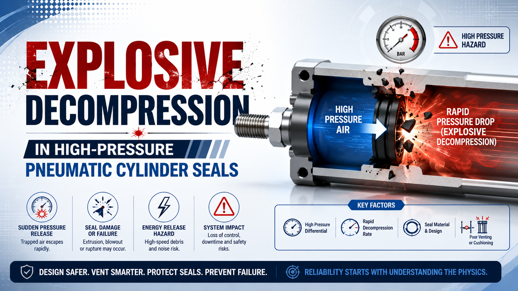
Explosive decompression is internal elastomer damage caused when absorbed high-pressure gas cannot escape as quickly as the pressure outside a seal falls. Also called rapid gas decompression or RGD, the mechanism can form blisters, pits, internal cracks, or complete ruptures. It is not a synonym for every seal that cracks after a pressure event.
Pressure alone does not establish the diagnosis. Parker states that RGD damage rarely occurs below 30 bar and lists pressure, decompression time, gas type, compound, and O-ring cross-section as governing variables (Parker O-Ring Handbook, accessed 2026). That boundary is far above the operating range of many standard pneumatic cylinders.
That gap matters.
Key Takeaways
- Operating at 100 psi does not automatically create an RGD application.
- Specify a tested compound, not only NBR, HNBR, or FKM.
- Confirm internal damage by sectioning the removed seal.
- Any slower pressure-release strategy must preserve the machine’s safety functions.
What Is Explosive Decompression in a Pneumatic Seal?
According to Parker, explosive decompression is failure mode 10.1.1.4 and has 3 possible outcomes: surface blisters, ruptures, or, with excessive trapped gas, destruction of the seal (Parker O-Ring Handbook, Section X, accessed 2026). Damage begins inside the elastomer, even when the first visible evidence appears on its surface.
All elastomers permit some gas permeation. During pressurization and dwell, gas dissolves into and diffuses through the seal compound. If external pressure falls slowly enough, that gas can migrate out with limited damage. If external pressure falls faster than the internal gas can escape, the resulting pressure difference expands microscopic voids and can tear the compound. Here, “explosive” describes the damage mechanism; it does not mean the entire cylinder necessarily explodes. Damaged seals can still leak suddenly and release stored pneumatic energy, so the resulting machine hazard requires a risk assessment and safe isolation procedure.
Gas needs time to leave.
Why a Universal 100 psi Threshold Is Misleading
Published Parker guidance says O-ring RGD damage rarely occurs below 30 bar, while the P1F pneumatic-cylinder catalogue specifies a 1 to 10 bar operating range for the cited configuration (Parker O-Ring Handbook; Parker P1F catalogue, accessed 2026). Therefore, 100 psi, about 6.9 bar, is not a universal RGD threshold.
This comparison does not prove that RGD is impossible in every lower-pressure installation. Parker also states that any compressed gas can cause the mechanism after sudden decompression and that gas composition matters. It does show why a single pressure number cannot replace a compound-specific and application-specific review. Begin with the exact cylinder data sheet. Never operate a standard cylinder above its published maximum merely because an upgraded seal fits the groove. Barrel, end caps, tie rods, retaining features, valve, tubing, fittings, sensors, and machine guarding all retain their own pressure limits.
Pressure limits still apply.
RGD becomes a more credible hypothesis when the system uses a special high-pressure cylinder, gas booster, long pressure dwell, large seal cross-section, fast blowdown, or a gas that dissolves readily in the compound. In an ordinary factory-air cylinder inside its rated range, abrasion, installation damage, side loading, extrusion, contamination, heat, or lubricant failure may be more likely.
Which Variables Control RGD Risk?
James Walker describes an RGD test using a 5.33 mm O-ring cross-section, 150°C temperature, 150 bar pressure, 8 cycles, and 1 hour dwell per cycle (James Walker, 2022). Those controlled variables show why an operating-pressure value by itself cannot describe seal risk.
Record the complete exposure and release history:
| Variable | What to record | Why it changes the result |
|---|---|---|
| Gas composition | Compressed air, nitrogen, carbon dioxide content, process gas, vapour or lubricant carryover | Solubility and diffusion differ by gas and compound |
| Maximum pressure | Dynamic pressure at the seal, not only regulator setpoint | Higher pressure can increase the absorbed-gas inventory |
| High-pressure dwell | Seconds, minutes or hours at pressure | Longer exposure gives gas more time to enter the elastomer |
| Release profile | Pressure at the sealed cavity versus time | The internal-to-external pressure difference drives expansion |
| Temperature | Minimum, normal and maximum measured values | Temperature changes diffusion and mechanical properties |
| Compound identity | Manufacturer, compound code, hardness, batch and approval | Polymer family alone does not define RGD resistance |
| Seal geometry | Cross-section, squeeze, groove fill and exposed area | Diffusion distance and stress distribution change |
| Mechanical duty | Reciprocation, speed, side load, pulsation and clearance | Wear or extrusion can create a competing failure mode |
What if no chamber-pressure trace exists? Do not substitute the upstream receiver or regulator gauge. Valves, quick exhausts, long tubes, check valves, blocked silencers, or trapped volumes can make pressure at the seal follow a different time history. Measure gas release at the relevant cavity during the actual shutdown or valve transition. Valve settings are not decompression profiles. Temperature, payload, tubing, silencers, and concurrent machine demand can all change the trace.
RGD risk is an exposure-and-release problem. The high-pressure dwell determines how much gas can enter the compound, while the release event determines how far the external pressure outruns diffusion. Treating either half alone produces an incomplete diagnosis.
Both parts matter.
How Does RGD Damage Differ from Extrusion and Wear?
Four visually distinct mechanisms relevant to a pneumatic seal are separated in Parker’s failure guide: explosive decompression, extrusion or nibbling, abrasion, and spiral failure (Parker O-Ring Handbook, Section X, accessed 2026). Similar leakage symptoms can therefore come from different physical causes and require different corrections.
| Failure mode | Typical evidence | Stronger supporting condition | Common wrong conclusion |
|---|---|---|---|
| Rapid gas decompression | Pits, blisters, internal splits or fissures | High-pressure gas dwell followed by rapid release | Any cracked seal must be RGD |
| Extrusion or nibbling | Material missing or feathered at a clearance edge, often on the low-pressure side | Excessive gap, soft compound, high pressure or pressure pulsing | A harder seal alone fixes the entire gland |
| Abrasion | Flattened, polished, scratched or worn dynamic surface | Roughness, poor lubrication, contamination or excessive temperature | Leakage after many cycles proves internal gas damage |
| Spiral failure | Angled spiral cuts or twisting around the ring | Rolling, eccentricity, side load or uneven surface | Pressure rating is the only variable |
| Installation damage | Cuts or nicks aligned with threads, ports or sharp edges | Inadequate chamfer, dirty assembly or incorrect tools | The compound was chemically incompatible |
| Thermal or chemical degradation | Hardening, softening, swelling, shrinkage or widespread cracking | Temperature or media outside the compound rating | Changing only the decompression rate will solve it |
Inspect the rod, barrel, wear rings, guide, groove, and lubricant during the same investigation. The cylinder side-loading guide explains why a pressure seal should not carry external side force, while the air-lubrication and seal-material guide covers friction and lubricant compatibility. Seal extrusion is displacement of elastomer into a clearance gap under pressure. Seal abrasion is progressive surface loss caused by dynamic contact. Both can create leakage, but neither requires gas to expand inside the compound. These definitions keep a pressure-related symptom from becoming an automatic RGD diagnosis.
Do not call damage RGD from a photograph alone. A blistered surface supports the hypothesis, but chemical swelling, thermal damage, contamination, or manufacturing defects can alter the appearance. The pressure history and internal cross-section must agree with the visual evidence.
The pattern must fit.
Material Family Is Not an RGD Rating
Three specific RGD-resistant compounds from different polymer families are named by Parker: N0552-90 NBR, KB163-90 HNBR, and V1238-95 FKM (Parker O-Ring Handbook, accessed 2026). This is direct evidence that compound formulation and qualification matter more than a generic claim that one polymer family always wins.
Many formulations exist within NBR, HNBR, FKM, polyurethane, and other seal families. Fillers, cure system, plasticizers, hardness, gas permeability, modulus, tear behaviour, temperature capability, and media compatibility can differ even when the polymer label is identical. Buying “HNBR” without a compound code and test evidence leaves the essential selection work unfinished. Can a polymer label settle the choice? No. An RGD-qualified compound is a specific formulation evaluated under documented specimen, gas, temperature, pressure-cycle, inspection, and acceptance conditions. Its qualification cannot be assigned to another formulation merely because both products use the same base polymer.
The compound code matters.
Compound data for KB163-90 identify a 90 Shore A HNBR material and list NORSOK M-710 and ISO 23936-2 RGD approvals (Parker compound report, 2017). That approval belongs to KB163-90 under the documented test scope; it does not automatically transfer to every 90 Shore A HNBR seal or prove suitability for a dynamic pneumatic piston seal. ISO 23936-2 describes qualification procedures for elastomers used in oil and gas production equipment and was confirmed current in 2022 (ISO). Its scope is not a blanket certification for industrial compressed-air cylinders. Connect the compound, specimen, gas, temperature, pressure cycle, acceptance criteria, and intended application before using it as evidence.
For example, a result obtained from a static 5.33 mm O-ring specimen does not automatically qualify a thinner dynamic rod seal. The compound may be promising, but the pneumatic application still needs its own wear, friction, groove, surface-finish, lubrication, and pressure-cycle review.
The NBR, FKM, HNBR and chemical-compatibility guide provides a broader material comparison. For an RGD application, request the exact compound report and confirm dynamic wear, temperature, air quality, lubrication, groove geometry, and pressure-release duty separately.
How Should You Inspect a Suspected RGD Failure?
James Walker’s RGD method sections each tested O-ring into 4 equal radial pieces and examines damage under at least 10-times magnification (James Walker, 2022). That destructive examination is far more informative than checking only the installed seal’s outer surface.
Use a controlled failure-analysis sequence:
- Isolate the machine under its approved energy-control procedure. Make every trapped or gravitational load safe.
- Save the evidence before changing the circuit. Export pressure trends, command history, alarms, cycle count, temperature, valve state, regulator setting, and the exact event that preceded leakage.
- Mark seal orientation and pressure side. Photograph the seal, groove, rod, bore, wear rings, edges, ports, fasteners, lubricant condition, and any debris before cleaning or moving the damaged part.
- Inspect without adding damage. Record pits, blisters, nibbled edges, polished wear bands, spiral cuts, hardening, swelling, and the location of each feature.
- Section the removed seal only when destructive examination is authorized. Inspect several radial faces under magnification for voids, splits, or fissures that are not visible externally.
- Identify the part: manufacturer, compound code, hardness, dimensions, batch, and certificate.
- Compare the evidence with competing failure modes. Pressure history plus internal cracking supports RGD; edge nibbling plus clearance points toward extrusion; one-sided wear points back to alignment or guidance.
Keep the failed seal.
In our experience, the most useful first comparison is seal damage versus its installed orientation. When our team analyzed failed cylinders, we first mapped evidence to the pressure side, a clearance edge, one side of the bore, and the assembly path. We found that this simple map often ruled out the wrong mechanism before material selection began.
Pressure-decay testing can quantify leakage after reassembly, but it cannot identify RGD by itself. Use the Pressure Decay Leak Rate Calculator only to estimate leakage from a controlled volume and pressure drop, then preserve the physical seal evidence for root-cause analysis.
How Can the Pneumatic Circuit Reduce Decompression Stress?
Three responses to explosive decompression are recommended by Parker: increase decompression time, select a resistant seal material, and consider a metal seal when pressure remains very high (Parker O-Ring Handbook, Section X, accessed 2026). Only the first response directly changes the pneumatic release profile.
Slower release can give absorbed gas more time to diffuse out. Possible implementations include staged pressure reduction, a controlled vent path, or a validated shutdown sequence. Device choice and timing depend on trapped volume, required stopping behaviour, exhaust capacity, contamination risk, temperature, and the machine’s safe state. Do not place an arbitrary restrictor in an emergency exhaust line. Any restriction that protects a seal but delays removal of hazardous pressure can make the machine less safe. ISO 4414:2010 covers significant hazards in pneumatic fluid-power systems and remains current after confirmation in 2021 (ISO). Apply the machine’s risk assessment and the exact component instructions.
Safety comes first.
Normal cycling and emergency energy isolation may need different paths. Routine shutdown can reduce pressure in stages, while a safety function may require faster exhaust. If those requirements conflict, change the seal compound, seal geometry, or actuator architecture instead of weakening the safety function. Check exhaust hardware under real flow. Blocked silencers may slow one event, while quick-exhaust valves may accelerate another. Record both cylinder-chamber pressures because the rod and cap ends can release through different valves, volumes, and restrictions.
An Engineering Qualification Checklist
ISO 23936-2 is a 66-page elastomer-qualification standard for oil and gas production, and ISO states that it supplements rather than replaces the applicable design codes and material requirements (ISO). A pneumatic-cylinder review needs the same discipline about scope: test evidence must match the actual component and duty.
Proof must match the task.
Before approving a high-pressure pneumatic seal, document:
- cylinder model, bore, stroke, seal groove, connected fittings, and the published pressure range for every pressure-containing component, including temperature derating and permitted transient conditions;
- seal manufacturer, compound code, hardness, dimensions and batch;
- gas composition, dew point, lubricant aerosol, compressor carryover, cleaning chemicals, and any process contamination that could reach the seal;
- minimum, normal and maximum temperature at the seal;
- pressure at both cylinder chambers during fill, dwell, motion and release;
- high-pressure dwell time and release time for normal, fault and safety events;
- cycle rate, total cycles, stroke speed, alignment and external side load;
- RGD test method, specimen size, gas mixture, temperature, pressure, cycles and acceptance grade;
- chemical compatibility, compression set, wear and extrusion evidence for the same compound;
- documented replacement criteria.
Ask the seal supplier whether its RGD qualification applies to static or dynamic service. Many published oil and gas approvals concern O-rings in static high-pressure equipment. Reciprocating pneumatic piston and rod seals add friction, wear, surface finish, lubrication, speed, and breakaway behaviour. Confirm that the cylinder itself is designed for the pressure as well. Seal substitution cannot uprate an actuator. Pressure-containing components and connected fittings must retain their individual ratings across temperature, pulsation, proof testing, maintenance, and foreseeable misuse.
When Should You Escalate to a Seal Manufacturer?
One exact HNBR compound, a 90 Shore A rating, and named RGD approvals appear in Parker’s KB163-90 report, which also limits its data to the referenced material (Parker, 2017). That product-specific boundary is the model for a defensible supplier review.
Escalate before release when:
- the cylinder operates above its standard catalogue range or uses a booster, accumulator, intensifier, or non-standard pressure vessel;
- the gas is not ordinary compressed air, or the composition is uncertain;
- dwell is long and blowdown fast;
- the seal cross-section, groove, clearance, or duty differs from the tested specimen;
- no compound code or RGD test report is available;
- the application combines high temperature, chemical exposure, side load, dry running, pressure pulsation, unusual surface finish, or restricted lubrication;
- failure could create an uncontrolled load, ejection, contamination, or personnel hazard;
- the same seal has failed twice after replacement, yet the pressure traces, physical evidence, and competing mechanisms have never been reconciled into a verified root cause.
Send the supplier raw traces and physical evidence, not only a pressure setpoint and a photograph. A useful technical request includes the two chamber-pressure histories, temperature, gas, dwell, release event, seal and groove dimensions, cycle count, damage orientation, and cross-section images.
Good records save time.
For temperature-driven degradation, compare the evidence with the cylinder seal temperature guide. For lubricant hardening or depletion, use the grease-aging guide. These failure modes can coexist with pressure damage.
For ownership, author context, or a technical correction, see About Bepto and Contact.
Explosive Decompression FAQs: What Should Engineers Verify?
James Walker’s RGD qualification example uses 8 pressure cycles from 150 bar to ambient with a 1-hour dwell, while the cited Parker P1F pneumatic cylinder operates up to 10 bar (James Walker, 2022; Parker P1F, accessed 2026). These different scopes explain why engineers must not transfer a test label or pressure threshold without checking the actual duty.
Can RGD occur in compressed air at 100 psi?
It is possible in principle because Parker says any compressed gas can contribute after sudden release, but 100 psi is not a universal RGD threshold. Parker also reports that damage rarely occurs below 30 bar. At ordinary cylinder pressure, investigate installation damage, abrasion, extrusion, side load, heat, and contamination before accepting an RGD diagnosis.
Does HNBR automatically prevent RGD?
No. Parker lists one qualified HNBR compound, KB163-90, alongside qualified NBR and FKM compounds. That proves polymer family alone is insufficient. Specify the manufacturer and compound code, then match its RGD test conditions, temperature, gas compatibility, hardness, geometry, dynamic wear, and intended service to the cylinder application.
Can surface inspection confirm RGD?
No. Surface pits or blisters support the hypothesis, but Parker notes that severe RGD reveals splits and fissures inside the O-ring. Preserve orientation and pressure history, then section the removed seal when authorized. Compare internal damage with extrusion, abrasion, spiral failure, installation cuts, thermal aging, and chemical swelling before assigning the root cause.
Should exhaust be throttled to prevent RGD?
Only after validating the complete machine response. Slower decompression can reduce seal stress, but an arbitrary restriction may delay a required pressure release or change actuator stopping behaviour. Separate routine shutdown from safety exhaust where necessary, follow the component instructions, and verify both cylinder-chamber pressure traces under normal and fault conditions.
Which data belong in a seal RFQ or failure report?
Include cylinder model, pressure rating, seal compound code, groove and cross-section, gas composition, temperature, chamber-pressure traces, high-pressure dwell, release time, cycle rate, lubrication, side load, and damage orientation. Add surface and section images plus the requested RGD test method and acceptance grade. A pressure setpoint alone is not enough.
Sources and technical references
- Parker O-Ring Handbook, Section X: Damage Analysis, explosive-decompression mechanism, identification and corrective actions.
- Parker O-Ring Handbook, Prädifa edition, risk variables and compound-specific RGD examples.
- James Walker RGD testing guide, 2022, example test conditions and inspection method.
- ISO 23936-2:2011, scope and status of elastomer qualification for oil and gas production.
- Parker KB163-90 compound report, 2017, compound identity and stated approvals.
- Parker P1F pneumatic-cylinder catalogue, model-specific pneumatic pressure range.
- ISO 4414:2010, pneumatic fluid-power system safety scope.