

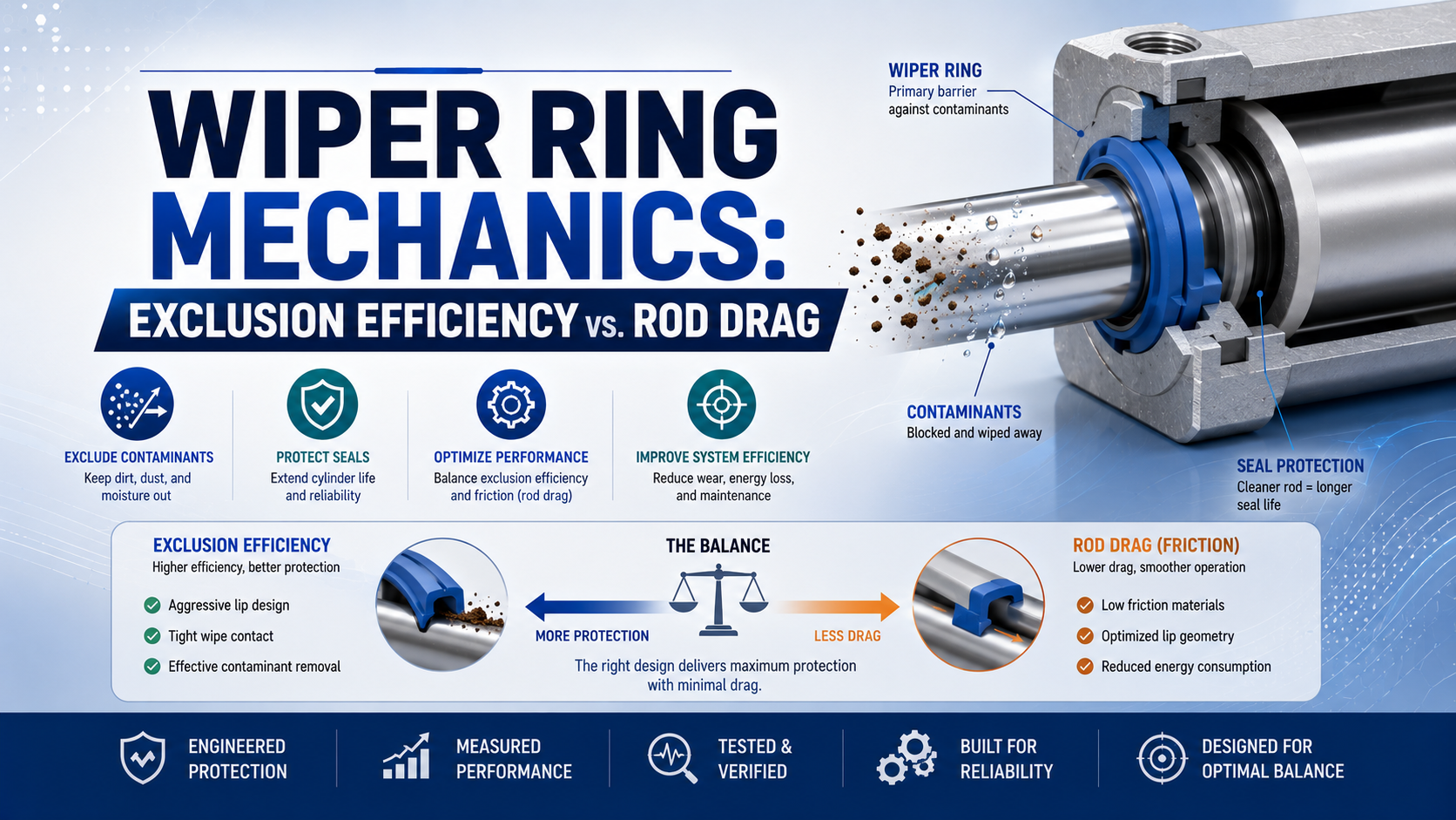
A pneumatic cylinder wiper ring is the rod-end component that removes dirt, moisture, chips, and other external contamination before it reaches the pressure seal and guide. Its contact with the rod also creates friction. Therefore, the design task is to exclude the application’s actual contamination without adding enough drag to disturb breakaway, low-speed motion, lubrication, or wear.
There is no universal “95% efficient” wiper or acceptable friction percentage. Both values depend on the profile, compound, rod, groove, lubricant film, temperature, speed, stroke, contaminant, and test method. Accordingly, a defensible comparison defines those conditions, measures exclusion and drag separately, and then checks them together.
Key Takeaways
- A wiper excludes contamination; a separate rod seal normally retains pressure.
- Measure breakaway and running drag under declared speed, temperature, dwell, and lubrication conditions.
- ISO 6195 standardizes wiper-ring housing dimensions, not exclusion efficiency or friction.
- Compare product-specific profiles with a controlled state table and test plan.
What Does a Wiper Ring Do in a Pneumatic Cylinder?
ISO 6195:2021 covers wiper-ring housings for reciprocating rods from 4 mm to 450 mm, but the wiper’s functional role is exclusion, not primary pressure retention (ISO 6195). In particular, a separate rod seal normally retains compressed air, while a guide or bearing reacts permitted transverse load. Combined seal-and-wiper profiles are the important exception.
In other words, three components may work close together at the rod end of a conventional cylinder:
| Component | Primary job | Evidence of a likely problem |
|---|---|---|
| Wiper or scraper. | Remove external contamination from the retracting rod. | Dirt behind the lip, chipped edge, loss of contact, or packed debris. |
| Rod pressure seal. | Retain compressed air as the rod reciprocates. | Air leakage at the rod end, worn sealing lip, extrusion, or hardening. |
| Rod bearing or guide. | Maintain alignment and carry the permitted radial reaction. | One-sided polishing, excess clearance, scoring, or rod contact. |
A combined rod seal/wiper performs more than one job in one profile. For example, Trelleborg lists separate pneumatic scrapers as well as rod seal/scraper combinations (Trelleborg). The installed drawing or part number must decide the function; the visible outer lip alone cannot prove whether a component also seals pressure.
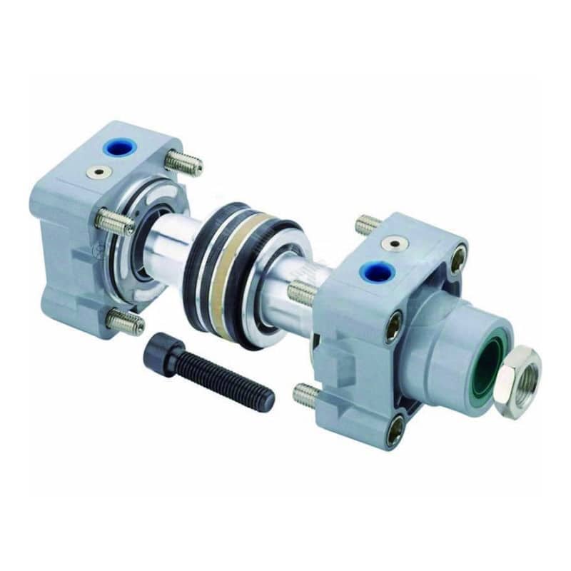
Notably, an exploded cylinder makes the functional boundary visible: the rod-end wiper, pressure seal, guide, piston seals, and static seals occupy different interfaces.
This boundary also changes troubleshooting. Specifically, air escaping at the rod end points first toward the pressure seal and rod surface. A damaged wiper may still have admitted the contamination that caused the failure. One-sided wear should move alignment, guide clearance, mounting, and side load above “harder wiper material” on the fault tree. The rod bearing and seal failure guide explains that mechanical load path.
Defining Exclusion Efficiency Without Inventing a Percentage
ISO 6195 specifies dimensions and tolerances for housings across a 4–450 mm rod range. However, it does not define a universal contaminant-exclusion test or passing percentage (ISO 6195). Exclusion efficiency means the share of a declared contaminant challenge that a wiper keeps outside a declared boundary under stated test conditions.
Specifically, one project can use the metric below. It compares applied and recovered mass.
Specifically, is the measured exclusion ratio, is the mass recovered beyond the defined wiper boundary, and is the mass delivered to the exposed rod. This equation is not an ISO 6195 rating. It is valid only when the collection and recovery method can account for the contaminant consistently.
Mass may be the wrong metric for water, adhesive mist, very fine powder, mixed grit, or biological residue. Alternatively, a test can use particle count by size class, collected moisture, optical coverage, conductivity, chemical residue, or cycles before a declared ingress limit.
In other words, the useful comparison has three layers:
- Challenge: contaminant identity, particle-size distribution, concentration, application rate, moisture, and direction of exposure.
- Motion: rod material and finish, speed, stroke, acceleration, dwell, temperature, orientation, and lubrication state.
- Result: ingress past a defined boundary, rod-film condition, wiper damage, drag, leakage, and test duration.
Without all three, a high percentage can be correct for one laboratory method and irrelevant to the machine. For instance, a fine flour dust test cannot establish performance against weld spatter, washdown chemicals, wet cement, salt crystals, ice, or adhesive buildup.
How Should Rod Drag Be Measured?
Parker separates dynamic seal friction into 2 conditions, break-out friction and running friction. Initial motion after dwell can differ sharply from steady travel (Parker O-Ring Handbook). Therefore, a wiper comparison should record both values in both stroke directions, with speed, dwell, temperature, and lubrication stated.
Incremental wiper drag is the force difference between controlled paired assemblies that are identical except for the wiper. Measure total rod-system friction with a load cell or validated pressure-and-area method. Meanwhile, keep the rod, guide, pressure seals, lubricant, temperature, speed, stroke, dwell, and assembly procedure unchanged.
| Measurement | What it reveals | Conditions that must be declared |
|---|---|---|
| Breakaway force after dwell. | Static adhesion, lubricant redistribution, material set, or initial lip contact. | Dwell time, temperature, rod position, pressure, and direction. |
| Running force. | Dynamic contact and lubricant-film behavior. | Speed, acceleration zone, measurement window, and direction. |
| Force variation across stroke. | Rod damage, runout, contamination, groove, or guide effects. | Position reference, repeat count, and rod orientation. |
| Force after contamination exposure. | Interaction between debris, lip damage, film, and contact. | Challenge material, cycles, cleaning policy, and ingress result. |
In contrast, do not estimate wiper drag by comparing two unrelated cylinders. Piston-seal friction, rod-seal friction, bearing clearance, bore finish, lubrication, alignment, pressure, and temperature can easily dominate the difference. Removing a wiper from a production cylinder and cycling it in contamination is also not a valid field test because it exposes the pressure seal and changes the system being evaluated.
In our experience, direction-preserving evidence makes seal inspections more conclusive. Importantly, mark the installed clock position before disassembly and photograph the lip and rod before cleaning. Then relate contamination tracks to rod scratches, guide polishing, load direction, and the stroke position where drag changes. Cleaning first can erase the evidence that separates wiper damage from misalignment.
Our team measured force most consistently when each paired assembly used the same dwell, motion profile, thermal state, and lubricant quantity. In fact, this procedure does not create a universal friction value. Instead, it removes avoidable test variation so the profile change has a clearer relationship to the measured force difference.
In addition, the dynamic versus static cylinder seal guide compares starting and running friction across seal types.
Converting Wiper Drag Into an Equivalent Pressure Difference
ISO 15552 covers detachable-mounting pneumatic cylinders with bores from 32 mm to 320 mm and a maximum rated pressure of 1,000 kPa (ISO 15552). Thus, a 50 mm bore is a practical example within that series. On its full-bore side, 10 N of incremental drag equals about 0.051 bar, not 0.5 bar.
The equivalent pressure difference is:
Specifically, is the pressure difference needed to overcome the measured incremental wiper force. is the paired-test force difference in newtons. is the pressurized effective piston area in square metres.
For example, use the full-bore piston area for this extension case. For a cylinder with , calculate the area first.
Next, apply .
This is a force-equivalence calculation, not a regulator-setting prediction. In contrast, retraction uses the annular area after subtracting rod area. Real motion also includes opposing-chamber pressure, other seal and guide friction, load, acceleration, flow losses, and exhaust back pressure.
That said, a cylinder can have enough theoretical pressure margin and still hesitate because breakaway and running friction differ. Use dynamic chamber pressures and a force trace before blaming the wiper alone. The large-bore friction-force guide provides the wider force-accounting context.
Why Do Lip Geometry, Material, and Lubrication Change Both Results?
Parker’s pneumatic A2 wiper is rated up to 2 m/s, while Trelleborg’s AWSW scraper catalog lists up to 1 m/s (Parker; Trelleborg). Importantly, both limits belong to specific profiles and compounds, not to all NBR or polyurethane wipers.
In particular, lip geometry determines the contact-pressure distribution and the direction in which debris or lubricant is encouraged to move. A sharp external edge may remove fine contamination effectively, but the complete profile must also tolerate rod runout, groove tolerance, thermal change, and the intended lubricant film. More lips do not automatically mean better exclusion or lower wear.
Material hardness is only one property. In addition, modulus, resilience, abrasion resistance, compression set, low-temperature response, hydrolysis resistance, chemical swelling, and lubricant compatibility influence contact. A nominal “90 Shore A polyurethane” from one product line does not establish another profile’s friction, temperature range, or life.
In other words, two interference locations must remain separate:
- Housing retention interference holds the wiper in its groove and may help block contamination around the outer diameter.
- Rod-lip interference creates contact at the moving rod and directly influences wiping, drag, film transport, heat, and wear.
Parker’s A2 catalog describes an oversized outer diameter for groove retention and separately credits lip geometry for smooth running and lubricant retention. Consequently, treating both as one universal 0.3–0.5 mm value can create an incorrect gland or excessive rod contact.
Notably, lubrication matters even in “oil-free” compressed-air service. Both Parker and Trelleborg pneumatic product data call for initial assembly lubrication on relevant profiles. A wiper that removes too much film can raise friction and accelerate rod-seal wear; one that leaves an excessive external film may attract dirt or create apparent leakage. The air lubrication and seal-material guide covers that compatibility decision.
Which Wiper Design Fits the Contamination?
Parker describes 2 pneumatic seal/wiper variants for contaminated piston rods that intentionally differ in wiping performance and friction, confirming that exclusion and drag are application-specific design choices (Parker Sealing Systems). Accordingly, select from the contaminant mechanism and full operating envelope, then verify the chosen profile’s drawing and test evidence.
| Environment | Main challenge | Wiper features to evaluate | Evidence to request |
|---|---|---|---|
| Fine dry powder. | Small particles carried on a thin rod film. | External lip sharpness, film control, antistatic needs, and groove sealing. | Declared powder and particle-size test, ingress result, and drag trace. |
| Abrasive grit or chips. | Cutting and scoring of lip and rod. | Wear-resistant profile, protected groove, rod coating, and debris escape. | Contaminant hardness and size, rod inspection, and post-test lip condition. |
| Water or washdown. | Moisture entry, hydrolysis, or corrosion behind the wiper. | Outer-diameter sealing, drainage, and hydrolysis-resistant compound. | Water exposure method, chemical compatibility, and groove corrosion review. |
| Sticky adhesive or resin. | Buildup that lifts or bonds the lip. | Scraping edge, non-stick behavior, cleanability, and compatible cleaner. | Deposit type, cleaning method, and force change across cycles. |
| Salt, ice, or outdoor debris. | Crystals, freezing, corrosion, and temperature cycling. | Dirt shield, low-temperature compound, drainage, and rod protection. | Temperature cycle, salt or water challenge, retention, and corrosion result. |
Start with the worst credible combination, not an average environment. For example, a packaging cylinder may face flour dust during production and alkaline washdown during sanitation. Similarly, an outdoor actuator may see dry grit, rain, salt, and freezing in one duty cycle. The wiper and compound must survive the combined exposure.
Then check the mechanical envelope:
- Rod diameter, coating, hardness, finish, runout, and existing damage.
- Groove drawing, housing type, lead-in edges, retention method, and tolerances.
- Stroke, peak and minimum speed, acceleration, dwell, orientation, and cycle rate.
- Minimum, normal, and transient pressure, including exhaust back pressure.
- Minimum and maximum temperature at the seal, not only room temperature.
- Compressed-air quality, initial grease, added lubrication, and cleaning chemicals.
- Acceptable breakaway, running drag, leakage, ingress, wear, and maintenance access.
That said, do not select solely from a generic material table. The PTFE versus polyurethane dry-air comparison explains why compound, profile, energization, lubrication, and hardware must be reviewed together.
Which Failure Patterns Separate Exclusion Problems From Drag Problems?
ISO 19973-3 measures pneumatic cylinder reliability under declared test conditions and permits lifetime to be reported in cycles or kilometres, rather than prescribing one replacement interval (ISO 19973-3). Accordingly, field inspection should use observed ingress, friction, leakage, motion, and wear evidence instead of a universal 6-, 12-, or 18-month wiper schedule.
| Symptom or evidence | First checks | Avoid this premature conclusion |
|---|---|---|
| Dirt found behind wiper. | Lip edge, rod track, groove retention, contaminant type, and exposure direction. | All internal seals have already failed. |
| High breakaway but normal running force. | Dwell, lubricant redistribution, temperature, material set, and rod cleanliness. | The wiper is too hard. |
| High running force across full stroke. | Lip interference, swelling, lubricant, rod finish, guide, and other dynamic seals. | The wiper alone creates all cylinder friction. |
| Force spike at one rod position. | Rod damage, buildup, runout, local corrosion, and alignment. | Supply pressure is unstable. |
| One-sided lip wear and rod scoring. | Bearing clearance, side load, mounting, rod straightness, and clock position. | A more aggressive wiper will fix the problem. |
| External grease or oil film. | Film transport, lubricant quantity, pressure-seal leakage, and combined-profile behavior. | The wiper is automatically the pressure leak. |
| Wiper pushed outward. | Groove retention, trapped pressure, blocked vent path, and pressure-seal leakage. | The replacement wiper only needs a tighter fit. |
The best inspection preserves sequence. First, record cylinder orientation and symptom location. Next, measure breakaway and running force and inspect the exposed rod. Isolate energy before disassembly. Finally, photograph the wiper in its groove, mark its clock position, and compare the lip track with guide wear, rod scratches, contamination, and pressure-seal condition.
Replacement is justified when the profile is cut, cracked, hardened, swollen, permanently distorted, loose in the housing, unable to contact the rod as designed, or associated with ingress beyond the accepted threshold. As a result, the interval should come from condition evidence, manufacturer instructions, machine risk, and service history. ISO 19973-3 test life is not a universal maintenance clock.
A useful trend record contains both contamination and motion data. If drag rises without ingress, the problem may be swelling, lubricant loss, temperature, or alignment. Conversely, ingress without much drag change suggests a damaged, lifted, worn, or poorly retained lip. If both rise together, embedded abrasive debris or rod damage becomes more likely.
What Data Should a Wiper Ring Supplier or RFQ Include?
ISO 15552 standardizes basic, mounting, and accessory dimensions for 32–320 mm cylinders up to 1,000 kPa (ISO 15552). However, it does not make internal wipers interchangeable across brands. ISO 6195 addresses wiper housings, yet the exact profile, compound, tolerances, rod, environment, and validation conditions still belong in the supplier review.
Send the following information:
- Cylinder manufacturer, series, bore, stroke, rod diameter, and drawing revision.
- Existing wiper and seal-kit part numbers, profile photographs, and groove dimensions.
- Rod material, coating, hardness, finish specification, runout, and observed damage.
- Normal and peak speed, cycle profile, dwell, orientation, temperature, and pressure.
- Contaminant identity, particle size or physical form, moisture, chemicals, and exposure direction.
- Compressed-air quality, lubricant policy, assembly grease, and cleaning process.
- Measured breakaway and running force in both directions.
- Leakage, ingress, motion, and wear thresholds that define acceptance.
- Required regulatory or traceability documents for the exact compound.
- Maintenance access, installation tools, lead-in geometry, and replacement procedure.
From our analysis of manufacturer drawings, housing dimensions alone cannot establish profile fit or function. Therefore, ask the supplier to separate catalog limits from test results. A temperature or speed range states the intended envelope; it does not prove exclusion against your contaminant. Conversely, an ingress result needs the rod, groove, motion, challenge, recovery method, sample count, and post-test drag.
Can an ISO 15552 repair kit be treated as a universal drop-in? No. ISO 15552 supports external dimensional interchangeability for the cylinder series. It does not require identical internal glands, wiper profiles, compounds, or seal-stack functions. Therefore, verify the exact replacement drawing before installation. For broader profile identification, use the industrial cylinder seal types guide.
Wiper Ring Mechanics FAQs
ISO 6195 covers wiper-ring housings for rods from 4 mm to 450 mm, while ISO 19973-3 evaluates cylinder reliability under declared conditions in cycles or kilometres. Those 2 standards explain why wiper selection needs exact dimensions plus application-specific exclusion, drag, leakage, and wear evidence rather than a universal efficiency or service interval.
Is a pneumatic cylinder wiper the same as the rod seal?
Usually not. The wiper removes outside contamination from the retracting rod, while the rod pressure seal retains compressed air. Combined rod seal/wiper profiles do exist, so identify the drawing and part number before diagnosing leakage. A damaged wiper may cause later rod-seal damage without being the component that initially leaks air.
How should wiper-ring exclusion efficiency be measured?
Define the contaminant, particle size or physical form, applied quantity, rod and groove, speed, stroke, cycles, temperature, lubricant, collection boundary, and failure threshold. Then measure recovered ingress by mass, particle count, moisture, optical coverage, or another declared method. A percentage without that test definition cannot support product comparison.
Can a tighter wiper ring slow a pneumatic cylinder?
Yes. More rod-lip contact can increase breakaway and running drag, disturb the lubricant film, generate wear, or worsen low-speed stick-slip. But total cylinder friction also includes rod and piston seals, guides, alignment, pressure, and contamination. Compare controlled paired assemblies before assigning the measured force change to the wiper.
How often should a pneumatic wiper ring be replaced?
Use manufacturer instructions, condition evidence, machine risk, and service history rather than a universal month or cycle count. Replace a wiper that is cut, cracked, hardened, swollen, loose, permanently distorted, or no longer excluding the declared contaminant. ISO 19973-3 test life is conditional evidence, not a maintenance calendar.
Are ISO 15552 cylinder wiper rings interchangeable between brands?
Not automatically. ISO 15552 standardizes selected external cylinder and mounting dimensions, while ISO 6195 covers certain wiper-housing dimensions. Neither standard guarantees identical internal grooves, lip profiles, compounds, seal-stack functions, or installation methods across brands. Verify the cylinder revision, groove drawing, rod specification, and exact replacement part before substitution.
Sources and technical references
-
ISO 6195:2021, cylinder-rod wiper-ring housing dimensions and tolerances for reciprocating applications covering rod diameters from 4 mm to 450 mm. Accessed 2026-07-23.
-
ISO 19973-3:2015, pneumatic piston-rod cylinder reliability test and reporting methods using cycles or kilometres under declared conditions. Accessed 2026-07-23.
-
ISO 15552:2018, basic, mounting, and accessory dimensions for 32–320 mm detachable-mounting pneumatic cylinders rated up to 1,000 kPa. Accessed 2026-07-23.
-
Parker Pneumatic Seals Catalog, product-specific pneumatic wiper and rod seal/wiper profiles, compounds, installation guidance, temperature, speed, and lubrication requirements. Accessed 2026-07-23.
-
Trelleborg Pneumatic Seals Catalog, AWSW scraper function, material, groove, speed, temperature, and initial lubrication data. Accessed 2026-07-23.
-
Trelleborg Pneumatic Rod Seal and Scraper Combinations, separate and combined pneumatic rod seal/scraper product families. Accessed 2026-07-23.
-
Parker O-Ring Handbook, break-out and running friction, dynamic sealing variables, surface condition, lubrication, and reciprocating-seal design context. Accessed 2026-07-23.
-
Parker Rod Wiper Design Optimization, contact force, force gradient, lubricant-film transport, ingress, leakage, and profile-specific test principles. Accessed 2026-07-23.
-
Parker Pneumatic Sealing Systems, contaminated-rod seal/wiper versions with different wiping and friction behavior. Accessed 2026-07-23.
-
Trelleborg Seal Research and Development Laboratory, visual reference for laboratory seal development and validation methods, not a pneumatic wiper rating source. Accessed 2026-07-23.