

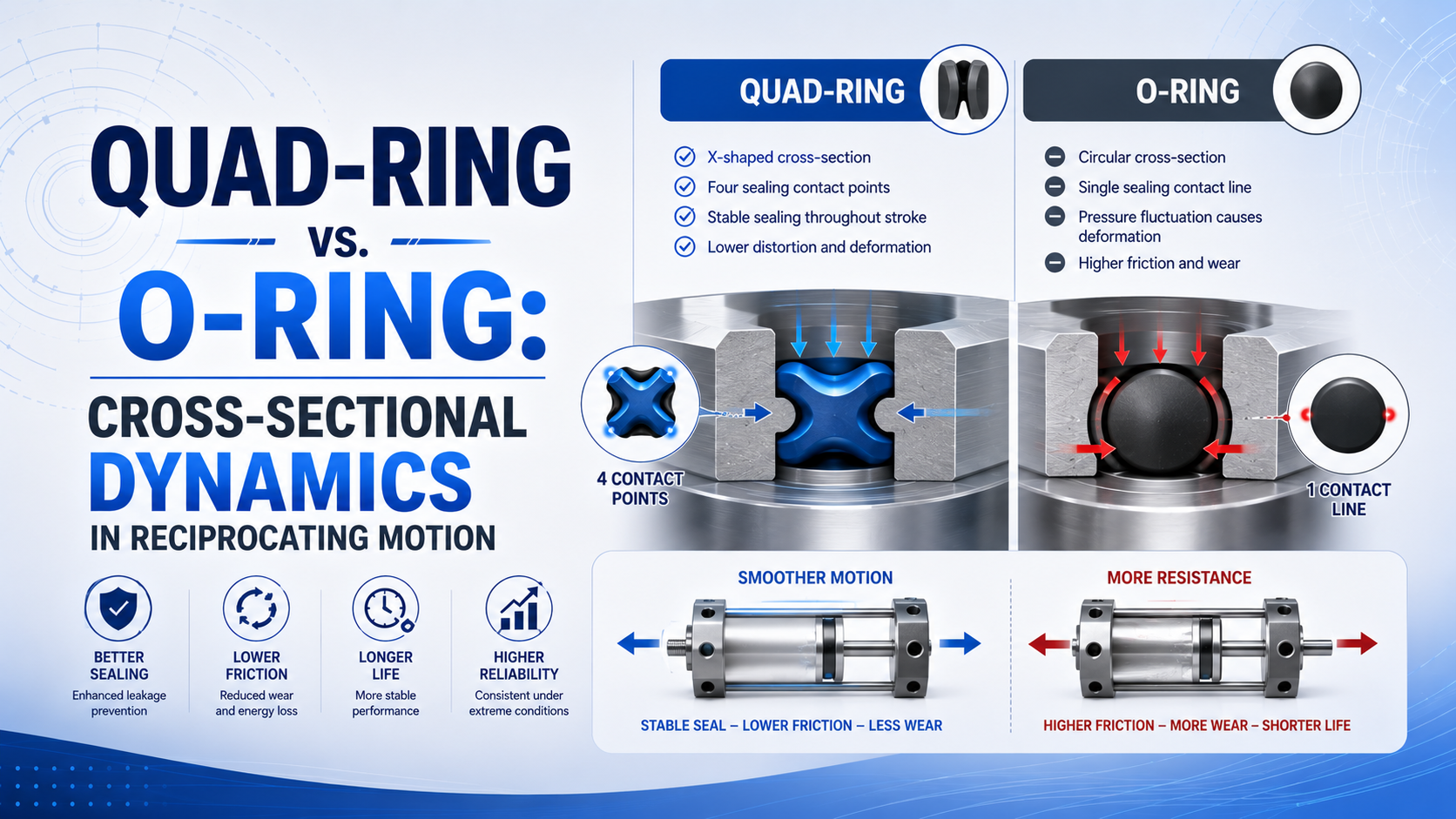
A Quad-Ring, also called an X-ring, can be a useful alternative to an O-ring in a reciprocating gland. Its four-lip profile creates two sealing lines on each working side and a lubricant reservoir between the lips. The shape can resist rolling better than a circular section, but it doesn’t guarantee lower friction, longer life, or freedom from twisting.
The correct choice depends on the exact groove, seal dimensions, compound, squeeze, clearance, moving surface, lubrication, pressure, temperature, speed, stroke, dwell, and alignment. Don’t treat an AS568 or ISO O-ring size as automatic permission to install an X-ring. Confirm the X-ring manufacturer’s gland drawing or an engineered cross-reference, then validate the assembled mechanism.
Key Takeaways
- Trelleborg defines its Quad-Ring as a double-acting four-lip seal for static and dynamic service.
- Parker lists 7 conditions that can promote O-ring spiral failure, including eccentricity, side load, uneven finish, and poor lubrication.
- A matching nominal size doesn’t prove groove, squeeze, clearance, material, or service compatibility.
What Does the X-Shaped Cross-Section Actually Change?
Trelleborg describes the Quad-Ring as a double-acting four-lip seal for static, reciprocating, oscillating, helical, and rotary duties. The useful difference isn’t “four times the sealing.” A paired-lip profile leaves a recessed area between adjacent lips. That area can retain lubricant and alter section deformation (Trelleborg, accessed 2026).
An O-ring is a circular elastomeric torus before installation. In a radial gland, controlled squeeze creates contact against the groove and moving surface. Pressure can shift and energize the section. That simplicity makes O-rings widely available and suitable for many static and dynamic applications when the gland and operating conditions are correct.
An X-ring is a four-lobed elastomeric section with recessed valleys. In a suitable gland, two lobes face the moving surface and two face the groove. The valleys between working lips can hold lubricant. Its non-circular outline can also reduce rolling tendency as the rod or piston reverses. Those are design tendencies, not universal measured results.
The most useful comparison is functional. Ask where sealing contact forms and how pressure moves the section. Check whether lubricant remains at reversal and whether the profile stays oriented during repeated strokes. For the wider distinction between moving and stationary interfaces, see the dynamic versus static cylinder seal guide.
Calling every lobe a “sealing point” can mislead. A four-lip outline doesn’t mean all four lobes carry equal load at once. The installed contact distribution changes with squeeze, dimensional tolerance, pressure direction, material stiffness, and hardware deflection. Only the selected manufacturer’s data or a validated contact analysis can quantify it.
Why Doesn’t a Quad-Ring Eliminate Spiral Failure?
Parker identifies 7 contributors to spiral failure. They are off-center parts, wide clearance with side load, uneven finish, poor lubrication, excessive softness, usually slow stroke speed, and installation damage. Twisting isn’t limited to toroidal O-rings. Other sections can twist when conditions permit it (Parker, accessed 2026).
Spiral failure is damage caused when part of a dynamic seal hangs up while another part slides or rolls. Repeated strokes accumulate torsion until diagonal markings, cuts, or a complete break appear. The ring may continue sealing for a time, so leakage alone can lag behind physical damage.
An X-ring’s valleys and lobes can help it stay oriented. They don’t remove eccentricity, side load, poor finish, dry contact, an oversized gland, excessive clearance, or installation damage. What if a failed X-ring shows diagonal wear? Treat that as evidence of system conditions, not proof that the compound was too soft.
Use the failure pattern to widen the inspection:
| Evidence | Likely condition to investigate | What not to assume |
|---|---|---|
| Diagonal or helical cuts | Rolling plus sliding, eccentricity, side load, lubrication, installation | That an X-ring makes the mechanism immune |
| One-sided polishing | Misalignment, guide clearance, bent hardware, transverse load | That a harder compound will correct the load path |
| Nibbled low-pressure edge | Extrusion clearance, pressure transient, hardness, backup support | That friction caused the damage |
| Flattened section | Compression set, temperature, compound, dwell, excessive squeeze | That the profile shape alone is wrong |
| Dry, glazed contact | Lubricant loss, surface condition, heat, incompatible cleaning | That all low-friction claims apply dry |
| Cuts at one location | Lead-in edge, port, thread, burr, assembly tool | That service motion created the first defect |
A piston or rod seal isn’t a guide bearing. If dynamic wear follows the load direction, inspect the cylinder’s bearing and alignment before changing profiles. The rod-bearing and seal-failure guide and the side-load wear guide cover that load path.
Why Can’t an X-Ring Automatically Use an O-Ring Groove?
ISO 3601-2:2025 is the third edition of the international standard for O-ring housing dimensions. Its scope covers class A and class B O-rings. It also says that special housing dimensions should be agreed between the maker and user. It does not certify every X-ring substitution (ISO, 2025).
ISO 3601-1 specifies O-ring inside diameters, cross-sections, tolerances, and designation codes. AS568 likewise provides O-ring size designations. An X-ring supplier may associate products with those nominal families. A shared size label is still only the start of the check (ISO 3601-1, confirmed 2022).
Trelleborg publishes separate Quad-Ring groove drawings for internal and external radial-dynamic applications, including designs associated with AS568 sizes. Follow that pattern. Select the exact X-ring and use its groove table. Don’t apply an assumed percentage adjustment to an O-ring gland (Trelleborg, accessed 2026).
Before approving a substitution, compare:
- seal inside diameter, nominal cross-section, and tolerances;
- groove diameter, depth, width, corner radii, and surface finish;
- installed squeeze, stretch or compression, and groove fill;
- extrusion gap, pressure direction, and backup-ring requirement;
- assembly chamfer, lead-in edge, ports, threads, and installation route;
- compound, hardness, temperature, medium, grease, and cleaning exposure;
- stroke, speed, dwell, reversal frequency, alignment, and expected travel.
Can a catalog X-ring sometimes fit an existing O-ring groove? Yes, when the seal supplier approves that exact combination or the hardware passes a controlled engineering review. For example, a ring may assemble easily yet have the wrong squeeze, extrusion clearance, lubricant volume, or installation-damage risk. Physical fit isn’t the acceptance test.
Treat “drop-in” as a drawing-controlled claim. It should name the original seal, replacement seal, groove revision, compound, pressure range, moving surface, and validation conditions. Without those fields, “same size” describes purchasing convenience rather than functional interchangeability.
Friction Is a System Result, Not a Profile Constant
Parker separates seal friction into 2 states, break-out friction and running friction. An actuator may hesitate after a dwell yet move smoothly once underway. It may also start cleanly while heating and wearing. One coefficient can’t describe both behaviors across different glands and compounds (Parker, accessed 2026).
The force needed to start or sustain motion comes from the complete tribological system:
- installed contact stress and pressure activation;
- compound stiffness, hardness, fillers, and surface treatment;
- groove tolerance, squeeze, stretch, and clearance;
- rod or bore material, coating, texture, waviness, and damage;
- grease type, quantity, distribution, aging, and compatibility;
- speed, acceleration, short-stroke reversal, dwell, and temperature;
- pressure direction, back pressure, side load, and alignment;
- wiper, wear ring, piston seal, rod seal, and other moving interfaces.
An X-ring may produce lower friction in a qualified comparison, and Trelleborg markets that advantage. The value can’t be transferred to every pneumatic cylinder as a fixed percentage. Even nominally identical elastomers can use different formulations, mold finishes, tolerances, or coatings.
Stick-slip deserves the same caution. A lubricant reservoir between X-ring lips may help at reversal. Unstable motion can also come from valve behavior, flow-control placement, changing pressure, guide friction, dried grease, surface damage, or excessive preload. Diagnose the whole motion system using the stick-slip measurement guide.
In our experience inspecting reciprocating seals, direction is valuable evidence. Mark the installed clock position before cleaning. Photograph every contact band. Then compare it with rod or bore marks, guide polishing, load direction, and the stroke location where motion changes. A loose bag of cleaned seals loses much of that diagnostic value.
Material choice also remains separate from profile choice. NBR, FKM, EPDM, HNBR, and other compounds respond differently to heat, oil, water, ozone, cleaning agents, and compression set. Use the seal material compatibility guide before assuming that an X-shaped version of the original compound solves the failure.
Which Applications Should Evaluate an X-Ring?
Trelleborg identifies 5 motion or application modes for Quad-Ring products: helical, oscillating, reciprocating, rotary, and static. The profile isn’t reserved for high-cycle cylinders. Start with the actual failure and supplier limits. Don’t rely on a universal cycle-rate, stroke, or pressure threshold (Trelleborg, accessed 2026).
An X-ring is worth evaluating when a qualified supplier can provide the correct dimensions and the application needs one or more of these characteristics:
- paired sealing lines in a compact elastomeric profile;
- a lubricant reservoir between dynamic lips;
- improved resistance to rolling or twisting in a suitable gland;
- bidirectional sealing in the stated pressure range;
- a specific compound, coating, or size offered in the X-ring profile;
- a documented replacement for an existing seal and groove.
An O-ring remains a sound choice when its existing design meets leakage, friction, wear, life, cost, and maintenance requirements. It also has an extensive standards and supply base. Replacing a successful O-ring merely because another profile looks more advanced adds qualification work without a defined problem.
Use this matrix as an evidence checklist, not a universal product ranking:
| Application condition | O-ring screening position | X-ring screening position | Evidence needed |
|---|---|---|---|
| Qualified existing gland with stable service | Retain unless requirements changed | Change only with a defined benefit | Baseline leakage, friction, wear, and service record |
| Repeated roll or twist evidence | Inspect gland, lubrication, alignment, and installation | Evaluate anti-roll geometry | Oriented failure inspection and controlled comparison |
| Low-speed reversal after dwell | Measure break-out and stick-slip | Evaluate lubricant reservoir and contact profile | Force and velocity traces after stated dwell |
| Chemical or temperature exposure | Choose the exact approved compound | Choose the exact approved compound | Compatibility of seal, grease, and hardware |
| High extrusion risk | Check clearance, hardness, pressure, and backup | Check the same limits | Supplier pressure-clearance data |
| Unverified legacy groove | Identify the original O-ring and drawing | Don’t assume nominal-size interchange | Dimensional inspection and supplier approval |
For a broader map of piston seals, rod seals, wipers, static seals, and cushioning elements, use the industrial cylinder seal types guide. This article stays with circular and X-shaped elastomeric sections in reciprocating service.
Inspection and Substitution Checklist
Trelleborg provides at least 2 separate radial-dynamic Quad-Ring groove arrangements, internal sealing and external sealing. A piston and rod gland load the seal in different directions. Record the interface and pressure side first. Then measure the removed ring or propose a substitute (Trelleborg, accessed 2026).
Use this sequence before ordering or installing a different profile:
- Identify the function. State whether the seal works on a piston, rod, shaft, bore, static joint, or another interface.
- Freeze the hardware identity. Record machine, cylinder, assembly, drawing revision, groove location, pressure direction, and original seal number.
- Preserve failure evidence. Mark orientation, photograph the installed condition, and keep debris and lubricant observations.
- Measure the gland. Check groove diameter, depth, width, radii, lead-in, port edges, clearance, and moving-surface diameter.
- Inspect the counterface. Record material, coating, hardness where relevant, surface specification, scratches, corrosion, waviness, and alignment.
- Define the duty. Include pressure, speed, stroke, reversals, dwell, cycle pattern, temperature, medium, contamination, cleaning, and lubrication.
- Select the exact seal. Obtain supplier dimensions, compound designation, hardness, tolerances, gland drawing, installation instructions, and operating limits.
- Control installation. Protect the seal from threads, ports, sharp edges, twisting, over-stretching, and incompatible assembly lubricant.
- Define acceptance limits. Set leakage, break-out force, running force, stick-slip, temperature, wear, and service criteria before testing.
- Retain the record. Store the approved drawing, seal batch or lot, setup, measurements, observations, and release decision.
Don’t diagnose a leaking cylinder by profile alone. Internal bypass, rod-end leakage, fixed-joint leakage, and contamination entry involve different interfaces. The dynamic versus static seal diagnostic helps separate them before parts are replaced.
How Should O-Ring and X-Ring Performance Be Validated?
ISO 19973-3 reports pneumatic-cylinder life using 2 service measures, cycles or kilometres, under declared tests and thresholds. It applies directly to piston-rod cylinders, not every standalone seal or rodless design. The method still offers a useful rule. Define the duty and failure limit before claiming longer life (ISO, confirmed 2021).
A fair comparison needs two matched assemblies or a controlled A/B sequence. Keep the cylinder, gland, moving surface, alignment, pressure, motion profile, temperature, air quality, grease, load, and acceptance criteria constant. Change only the approved seal profile and any documented gland change required by that profile.
Record at least:
- static leakage and dynamic leakage in both directions;
- break-out force after defined dwell periods;
- running force or pressure differential through the stroke;
- low-speed velocity stability and reversal behavior;
- seal and nearby hardware temperature after stabilization;
- pressure, speed, stroke, cycle count, and accumulated travel;
- visible wear, contact bands, twist, extrusion, debris, and surface damage;
- maintenance, grease condition, and any permitted adjustment;
- the exact failure threshold and first-failure event.
Why track both cycles and travel? A short-stroke actuator can accumulate many reversals with little sliding distance, while a long-stroke actuator can cover substantial distance in fewer cycles. Reporting only months or cycles can hide the mechanism that governed wear.
Don’t turn one successful test into a universal “two to four times longer” promise. The result belongs to the tested seal, compound, gland, counterface, lubricant, duty, environment, sample, and failure definition. For dry-air material comparisons and component-level friction evidence, see the PTFE versus polyurethane seal guide.
Cost comparison should follow the same boundary. Count seal price, installation labor, planned and unplanned downtime, leakage, collateral damage, inspection, and verified service measure. A lower total cost is credible only when those inputs come from the actual machine or a representative test, not a fictional downtime rate.
Quad-Ring vs. O-Ring FAQs
Three official sources frame these answers. Trelleborg publishes X-ring geometry and grooves. ISO 3601 covers O-ring housings. Parker ties spiral failure to setup and service. The comparison is conditional, not universal (Trelleborg; ISO; Parker, accessed 2026).
Is a Quad-Ring the same as an X-ring?
Quad-Ring is Trelleborg’s branded name for its four-lip X-shaped seal profile, while X-ring is the common geometric description used across the market. Products that share the general shape aren’t automatically dimensionally or materially identical. Use the selected supplier’s part number, compound, tolerances, groove drawing, and operating limits.
Can an X-ring directly replace an O-ring of the same nominal size?
Sometimes, but nominal size alone isn’t approval. ISO 3601 and AS568 describe O-ring dimensions or housings, while X-ring manufacturers publish their own gland data. Confirm groove depth and width, squeeze, stretch or compression, fill, clearance, radii, pressure direction, compound, lubricant, moving surface, and duty before substitution.
Does an X-ring always have lower friction than an O-ring?
No. The X-shaped profile can reduce rolling tendency and retain lubricant between working lips. Suppliers may publish lower-friction claims for qualified products. Actual break-out and running force still depend on compound, squeeze, pressure, surface, grease, temperature, speed, dwell, alignment, and every other dynamic seal in the assembly.
Can a Quad-Ring still twist or suffer spiral damage?
Yes. Its non-circular section can improve orientation in a suitable gland, but Parker notes that twisting isn’t limited to O-rings. Off-center parts, side load, wide clearance, uneven finish, poor lubrication, unsuitable hardness, slow motion, and installation damage can still create rolling, torsion, wear, or cuts.
Should seal material or cross-sectional shape be selected first?
Define the interface and exposure first, then select the complete seal. Profile controls contact and deformation, while compound controls properties such as chemical compatibility, temperature response, hardness, and compression set. Groove, moving surface, lubricant, pressure, motion, contamination, and installation must be reviewed with both rather than after either.
Sources and technical references
- Trelleborg, Quad-Ring / X-Ring Product and Groove Information, accessed July 23, 2026.
- Trelleborg, Quad-Ring Design Instructions, accessed July 23, 2026.
- Parker, O-Ring Handbook ORD 5700, accessed July 23, 2026.
- ISO 3601-1:2012, O-Ring Dimensions and Designation Codes, confirmed 2022.
- ISO 3601-2:2025, O-Ring Housing Dimensions, published 2025.
- ISO 19973-3:2015, Pneumatic Cylinder Reliability Testing, confirmed 2021.