

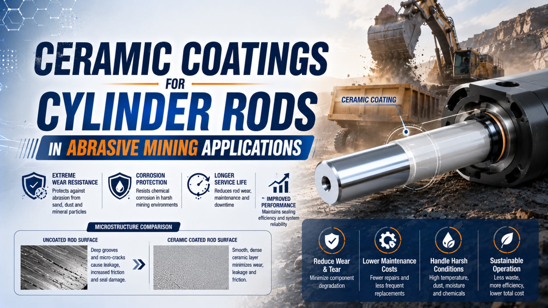
Ceramic coatings for cylinder rods can improve resistance to abrasive dust, wet fines, and particle erosion, but the buying term covers very different surface systems. HVOF tungsten carbide and chromium carbide coatings are usually cermets with a metallic binder. Alumina is an oxide ceramic. Their behavior cannot be ranked by hardness alone.
For a mining cylinder, the finished rod must work as a surface system: substrate, bond, coating chemistry, spray process, ground texture, rod seal, wiper, bearing alignment, and contamination protection. A supplier’s successful hydraulic-rod application can establish technical relevance. It cannot guarantee the same life on a pneumatic cylinder. Pressure, speed, seal design, and exposure may all differ.
Key Takeaways
- Oerlikon reports more than 98% density for one HVOF Cr₃C₂-NiCr product, not for every carbide coating.
- Select against the identified wear and corrosion mechanisms.
- Specify the finished seal surface and inspection method.
- Compare lifecycle cost with site records, not a generic life multiplier.
What Does “Ceramic Coating” Mean on a Cylinder-Rod RFQ?
The 2017 ISO/TR 14232-2 distinguishes cermets from metals and ceramics. It then compares thermal-spray powder chemistry across eight wear mechanisms. That classification matters on an RFQ. WC-CoCr and Cr₃C₂-NiCr contain hard carbide particles in a metallic binder. Al₂O₃ is an oxide ceramic (ISO, 2017).
A cermet coating is a composite surface with ceramic hard particles held in a metallic binder. Binder chemistry is functional. Oerlikon’s Metco 5847 feedstock contains 86% tungsten carbide as the hard phase and a cobalt-chromium matrix that binds the carbide particles. Chromium in that matrix is intended to improve corrosion behavior. Fine carbide grains contribute abrasion, erosion, and fretting resistance (Oerlikon Metco 5847, retrieved 2026-07-23). Plasma-sprayed alumina presents a different microstructure and porosity concern. ISO/TR 26946:2011 describes metallographic porosity measurement and specifically identifies plasma-sprayed Al₂O₃, ZrO₂, and TiO₂ as applicable coating families (ISO/TR 26946). Material names do not erase the need to measure pores, cracks, and interfaces.
HVOF describes an application process, not one coating composition. Oerlikon lists a flame temperature around 2,800°C and particle velocity from 400 to 800 m/s for its HVOF process overview. High-velocity powder can create dense carbide coatings, but final properties still depend on feedstock, gun, fuel, substrate preparation, spray parameters, thickness, and finishing (Oerlikon HVOF, retrieved 2026-07-23). First define which “rod” is being coated. Piston rods cross the pressure boundary through a seal and wiper. External guide rods on guided or rodless actuators may carry bearing load without passing through that seal. Consequently, one coating defect can cause leakage in the first design and guide wear or binding in the second. Our rod-bearing guide explains the load-path distinction.
Process names are not specifications.
Which Mining Failure Mechanism Should Drive Coating Selection?
Mining-specific Oerlikon guidance lists four demands for its HVOF and electric-arc cylinder solutions: corrosion, vibration or shock, temperature variation, and application-specific abrasion. A rod exposed to dry silica dust does not present the same surface problem as one retracting through wet chloride-bearing fines (Oerlikon Mining, retrieved 2026-07-23).
Start with the physical damage found on the returned rod and seals:
| Evidence | Likely mechanism | Coating implication | System action before upgrading |
|---|---|---|---|
| Long scratches parallel to travel | Two-body abrasion or one trapped particle | Hardness and supported carbide structure may help | Improve scraping, shielding, and cleaning |
| Broad matte wear with loose fines | Three-body abrasion | Evaluate abrasion-tested coating and finished texture | Stop particles accumulating at the wiper |
| Rounded pits near exposed stroke | Particle erosion or corrosive pitting | Balance erosion resistance with environmental corrosion | Identify particle velocity, moisture, and chemistry |
| Rust beneath a lifted or porous layer | Under-coating corrosion | Binder chemistry, density, sealing, and edge coverage matter | Define wet exposure and inspect coating transitions |
| Chips near shoulders or tool marks | Impact, poor edge design, or handling damage | Toughness and edge geometry may dominate hardness | Protect the rod during assembly and service |
| Seal wear concentrated on one side | Misalignment or side load | A harder surface will not correct bearing stress | Correct the load path and guides first |
Hard particles do not automatically cut a softer surface on every stroke. Damage requires contact, load, relative motion, and a path into the interface. Effective wiping can be more valuable than a harder coating when the ingress route remains open. Conversely, one embedded particle can score a highly polished surface repeatedly. Side loading deserves its own branch. If the rod bearing or external guide is overloaded, contact pressure becomes uneven and the rod may traverse the seal at an angle. Coating hardness cannot realign the mechanism. Use the cylinder side-loading guide before specifying a more expensive rod surface.
Name the mechanism first.
Corrosion and abrasion may act together. A pore, crack, or unprotected edge can admit moisture to the substrate. Corrosion products then create a raised cutting feature under the seal. In that case, a coating with excellent dry abrasion performance may still fail because the binder, porosity, edge treatment, or coating continuity does not match the wet mine.
How Do HVOF Carbide Systems Differ?
Oerlikon’s Metco 5241 sheet identifies a Cr₃C₂-NiCr HVOF product with greater than 98% coating density and lists hydraulic rods as an application. It directs more severe abrasion or erosion to other named chemistries instead of presenting 5241 as a universal rod coating. The sheet also separates acidic-salt service from lower-temperature needs (Oerlikon Metco 5241, 2022).
| Coating family | Useful starting characteristic | Selection question | Procurement risk |
|---|---|---|---|
| WC-Co | Hard carbide phase with cobalt binder | Is dry abrasion dominant and is the environment compatible with the binder? | Treating all WC-Co powders and spray parameters as equivalent |
| WC-CoCr | Carbide wear resistance with chromium added to the binder | Does the wet or corrosive exposure justify the selected matrix? | Claiming universal corrosion resistance without an exposure test |
| Cr₃C₂-NiCr | Chromium-carbide system used for erosion, oxidation, and elevated-temperature duties | Is temperature or solid-particle erosion important in this actual cylinder? | Selecting it only because “chromium carbide” sounds corrosion-proof |
| Al₂O₃ and other oxides | Electrically insulating or chemically stable oxide-ceramic options in some duties | Can the coating tolerate impact and achieve the specified finished seal surface? | Ignoring porosity, brittleness, finishing damage, and edge chipping |
| Hard chrome | Established rod finish with a mature repair and inspection base | Does qualified hard chrome already meet the actual failure boundary? | Replacing it without proving the old finish caused the failure |
Exact powder designation belongs on the drawing or purchase specification. “Tungsten carbide coating” omits carbide grain size, binder chemistry, powder manufacture, particle-size distribution, spray process, and permitted equivalent. Two coatings with the same nominal WC percentage may differ after decarburization, oxidation, porosity, residual stress, and grinding. Never copy a high-temperature material limit into the cylinder assembly rating. Metco 5241 lists 870°C for that coating product. Pneumatic seals, grease, magnets, sensors, adhesives, and dimensional fits usually impose much lower limits. Material survival is not assembly approval.
Published limits belong to named products.
Field life has the same boundary. For example, Oerlikon’s brochure shows one HVOF-sprayed hydraulic rod at 3,200 service hours and a hard-chrome rod at 682 hours. This supplier application is not a controlled universal ratio for mining pneumatic cylinders (Oerlikon Alternatives to Hard Chromium, 2014). It justifies evaluation, not a promised 4.7-fold extension.
Why Does the Finished Seal Surface Matter More Than Hardness?
Parker uses four parameters, Ra, Rp, Rz, and Rmr, for reciprocating seal surfaces and states that PTFE generally needs a smoother finish than polyurethane or most rubber compounds. A microhardness certificate cannot prove that a coated rod is ready to cross a pneumatic seal (Parker, retrieved 2026-07-23).
Ra is only an arithmetic average. It can hide one deep longitudinal score, a sharp isolated peak, open porosity, or a coating transition that cuts the wiper. Rz adds profile-height information. Rp helps expose peak height. Rmr describes supporting material at a stated level. Drawings also need the measurement standard, filter, cutoff, evaluation length, trace direction, and locations. Grinding and polishing are part of the coating system. Aggressive finishing may remove too much coating, expose pores, create thermal damage, alter residual stress, or leave an unsupported edge. Uniform appearance proves little. An as-sprayed surface can still be unsuitable for a dynamic seal. A mirror-like result does not prove adequate lubricant retention or correct material ratio.
The seal runs on the finish.
Specify final diameter, roundness, straightness, cylindricity, runout, and surface texture after coating and finishing. Include the entire seal travel. Shoulders, grooves, threads, wrench flats, and coating runout zones need protected installation paths so the seal lip never crosses a sharp or uncoated edge. Our chrome-versus-nitride rod-finish guide explains how surface hardness differs from texture and integrity. For measurement details, the Ra-versus-Rz guide shows why two surfaces with the same average roughness can interact differently with a seal.
A coating can pass its material certificate and still fail the cylinder. The certificate may describe powder chemistry, coupon hardness, or a witness-sample cross-section. The seal runs on the finished production rod. Acceptance must connect both records. The evidence package should trace the lot to its dimensions and surface measurements. It must also include defect inspection plus a functional test of the assembled cylinder.
Coating Specification and RFQ Checklist
ISO 14922:2021 sets quality requirements for thermal-spray manufacturers. ISO 14917:2017 standardizes terminology and classification. Referencing both helps, but the buyer must still define the component and coating system. The purchase specification also needs an inspection plan, acceptance limits, and a required record package (ISO 14922; ISO 14917).
Build the RFQ around inputs the coating supplier can act on:
- Identify the cylinder and rod function. State whether the surface crosses a pressure seal, runs in an external bearing, or performs both duties.
- Provide substrate grade, heat treatment, current coating, diameter, length, drawings, tolerances, and any fatigue-sensitive region.
- Describe dry dust, wet slurry, chlorides, acidity, cleaning chemicals, temperature, UV exposure, and storage conditions.
- Quantify stroke, speed, cycle rate, side load, shock, vibration, dwell, pressure, and the exposed portion of the rod.
- Name the proposed powder designation, binder chemistry, spray process, nominal thickness, permitted range, masking, edge treatment, and finishing route.
- Define the rod seal, wiper, bearing, lubricant policy, protective boot or guard, and the counter-surface parameters supplied by the seal manufacturer.
- State required reports: powder lot, process route, coating thickness, hardness method, porosity method, adhesion test, texture traces, dimensions, defects, and final inspection.
- Set cylinder-level acceptance criteria for leakage, breakaway, running motion, contamination exposure, and endurance.
Avoid “or equivalent” unless the equivalence criteria are written. Any substitute must match the functional coating family, powder chemistry, binder, spray process, post-finish capability, corrosion requirement, and qualification evidence. Price and headline hardness are not enough. Repair work needs additional substrate information. Record original diameter, previous coating and stripping history, minimum allowable base diameter, corrosion depth, straightness, fatigue-critical features, and the permissible thermal history. Recoating capability does not automatically make a rod reusable.
Equivalence needs evidence.
How Should Coated Rods Be Inspected and Accepted?
Published in 2017, ISO 14916 gives a 26-page tensile adhesive-strength procedure for thermally sprayed coatings. It can compare coatings made from the same or similar feedstocks and spray processes, but it is not intended to provide an absolute durability value in service (ISO 14916, confirmed 2022).
Use a layered acceptance plan:
| Inspection layer | Typical evidence | What it can establish | What it cannot establish alone |
|---|---|---|---|
| Feedstock and process | Powder certificate, lot, spray equipment, qualified procedure, parameter record | Traceable input and process consistency | Final seal-surface quality |
| Coating cross-section | Thickness, porosity, cracks, interfaces, carbide and binder condition | Microstructural conformity on the sampled location | Defect-free condition across the full rod |
| Mechanical properties | Stated hardness method and adhesion test | Comparison with the qualified coating system | Mine-specific cylinder life |
| Finished rod | Diameter, geometry, texture traces, visual or specified NDT results | Conformance of the production sealing surface | Dynamic leakage and motion |
| Complete cylinder | Leakage, breakaway, speed, endurance, contaminated exposure | Assembly performance under the defined test | Performance outside the test envelope |
Sampling must be traceable. Witness coupons sprayed near the rod can support process control, but their thermal mass, angle, preparation, and finishing may differ from the component. State whether each result came from the production rod, a sacrificial sample, or a coupon. Measure surface texture at several locations around and along the seal path. Preserve the instrument, filter, cutoff, evaluation length, trace direction, calibration, and result plot. One Ra value near an accessible rod end cannot represent the entire stroke.
Inspect coating runouts and transitions deliberately. These areas concentrate masking errors, thin edges, overspray, grinding steps, and possible seal damage during assembly. Protect the finished surface during shipping. Receiving inspection should reject nicks, corrosion, contact marks, and damaged packaging before the rod enters a cylinder. Finally, validate the assembled unit with its production seal, wiper, bearing, lubricant, pressure, load, and speed. Record leakage and motion in both directions. Repeat after the relevant dwell and contamination exposure. Define the failure criterion before the endurance run starts.
Traceability closes the gap.
Protecting the Rod After Installation
Abrasion guidance from Oerlikon distinguishes two-body wear from three-body abrasion, where loose grit damages sliding surfaces. Particles still need a path. A harder coating can resist scratching, but it does not stop a third body from entering the seal contact. Mining reliability still begins with exclusion and load control (Oerlikon Abrasion, retrieved 2026-07-23).
Place shielding around the actual contamination path. Boots can help where stroke, temperature, geometry, and inspection access permit them. Guards may deflect falling rock without trapping wet fines. Where wet material can pack behind a boot, choose protection that keeps the rod accessible for inspection and safe cleaning. Wiper selection must match particle size, rod texture, speed, and allowable drag. No universal percentage describes exclusion. Clean without creating the next defect. Avoid wire brushes, abrasive pads, and tools that can score or chip the finished surface. Compressed-air cleaning can drive dust into the seal or expose personnel to airborne particles. Follow the mine’s dust-control and lockout procedures.
Keep contaminants away from the seal.
Check alignment after impacts and maintenance. Uneven seal wear, one-sided bearing marks, localized coating polish, or a repeated scratch at the same angular position may indicate side load. New coating will not survive if the load path remains wrong. Set inspection intervals from observed wear progression and failure consequence. Begin with a conservative baseline. Document coating and seal condition, then adjust the interval only after enough comparable inspections exist. The extreme-environment actuator contamination guide provides a broader exclusion and guarding framework.
How Should Lifecycle Cost Be Compared?
One 2014 Oerlikon brochure reports 3,200 service hours for an HVOF-coated hydraulic rod and 682 hours for a hard-chrome comparison. Those figures support a site trial, not a pneumatic-cylinder ROI promise. Cost analysis needs mine-specific failure records, labor, access, production loss, and qualified replacements (Oerlikon).
Compare matched service intervals rather than purchase price alone:
- Record installed cost.
- Use verified removal and installation labor from the same equipment class, including access equipment and every isolation step required at that location.
- Separate maintenance from production loss.
- Count replacement seals, rod refurbishment, collateral bearing damage, cleanup, freight, inspection, supervision, and any changed wiper, boot, or guard.
- Normalize hours, strokes, load, exposure, and maintenance practice.
- Assign residual value only when an inspected rod has a documented stripping and recoating route with adequate remaining substrate, geometry, and fatigue margin.
Run a controlled trial when failure costs justify it. Keep one qualified baseline configuration and one candidate coating on comparable equipment. Define the failure threshold, inspection schedule, operating data, and decision date before installation. If the mine changes the wiper, boot, alignment, or maintenance practice at the same time, record those changes rather than assigning the entire gain to the coating. A defensible economic output is a break-even service interval, not a promised savings percentage. Purchasing can determine how long the coated rod must remain acceptable before its higher installed cost is recovered. Engineering then decides whether the qualification evidence makes that interval credible for the named machine and exposure.
Let site records decide.
Engineering Conclusion
With eight wear types, ISO/TR 14232-2:2017 provides a useful starting point for an abrasive mining rod. “Ceramic” is not a performance specification. Define the damage mechanism, then qualify the substrate, coating system, binder, spray process, finish, seal interface, inspection package, and complete cylinder (ISO).
HVOF carbide coatings can be strong alternatives to hard chrome when abrasion, erosion, corrosion, or coating-process constraints justify them. They do not carry a universal hardness, service-life, or ROI advantage. The named product and qualified process own the published data.
Approval belongs to the finished rod and assembled cylinder. Require traceable production records, inspect the complete seal path, preserve alignment and contamination control, and verify leakage plus motion under the mine’s actual conditions. That evidence turns a coating label into an engineering decision.
Mining Cylinder Coating FAQs: What Should Buyers Ask?
ISO 14916:2017 limits adhesion results to comparable coating systems and rejects their use as absolute service-durability values. Buyers should therefore ask five questions that connect coating identity, rod finish, seal compatibility, inspection records, and site validation before approving an HVOF carbide or oxide-ceramic surface for mining duty.
Is tungsten carbide coating the same as a ceramic coating?
Not exactly. A typical HVOF WC-CoCr coating is a cermet. Tungsten-carbide particles provide its hard phase; a cobalt-chromium matrix binds them. By contrast, Al₂O₃ is an oxide ceramic. Commercial language may group both as ceramic coatings, although they require different processing, finishing, porosity control, and inspection.
Does a higher HV value guarantee longer cylinder-rod life?
No. Hardness describes only part of indentation and wear resistance. Coating pores or grinding damage can expose the substrate. Misalignment can overload one side of the seal. Wet fines may attack the binder. Compare complete systems against the failure recorded on the returned parts, then validate the finished rod under the same contamination, alignment, load, speed, and maintenance conditions.
Which surface-finish value should appear on the rod drawing?
Use the parameters required by the selected seal and coating system, not one universal Ra limit. One number is insufficient. Parker’s reciprocating guidance uses four parameters: Ra, Rp, Rz, and Rmr. The rod drawing must identify the measurement method and locations. Add lay, defect, diameter, roundness, straightness, and runout requirements separately.
Can an adhesion test predict mining service life?
No. ISO 14916 permits comparison between the same or similar feedstocks and thermal-spray processes. It does not produce an absolute service-durability value. Treat adhesion as one process-control result. Mining approval also needs a conforming microstructure and finished rod, followed by leakage, motion, contamination, and endurance tests on the assembled cylinder.
Can an existing worn rod simply be stripped and recoated?
Only after engineering inspection. Every stripping and refinishing cycle removes material. Corrosion can leave the substrate below its allowable diameter, while impact may introduce cracks or bending. Review previous processing and substrate grade first. Then verify remaining geometry, defect depth, fatigue-sensitive features, heat-treatment limits, and the proposed coating allowance.
Sources and technical references
- ISO/TR 14232-2:2017, Thermal spraying, Powders, Part 2: Comparison of coating performance and spray powder chemistry. Used for wear-mechanism, corrosion-environment, powder-chemistry, ceramic, metal, and cermet selection boundaries. Retrieved 2026-07-23.
- ISO 14917:2017, Thermal spraying, Terminology, classification. Used for thermal-spray process and material terminology. Retrieved 2026-07-23.
- ISO 14922:2021, Thermal spraying, Quality requirements for manufacturers of thermally sprayed coatings. Used for manufacturer quality-system context. Retrieved 2026-07-23.
- ISO 14916:2017, Thermal spraying, Determination of tensile adhesive strength. Used for adhesion-test scope, comparability, and the prohibition on interpreting it as absolute service durability. Confirmed current in 2022; retrieved 2026-07-23.
- ISO/TR 26946:2011, Standard method for porosity measurement of thermally sprayed coatings. Used for metallographic porosity evaluation of plasma-sprayed oxide coatings. Retrieved 2026-07-23.
- Oerlikon Metco, HVOF Process Overview. Used for the stated 2,800°C flame temperature, 400 to 800 m/s particle velocity, powder feedstock, and process boundaries. Retrieved 2026-07-23.
- Oerlikon Metco, Mining Hydraulic Cylinder Solutions. Used for mining-specific abrasion, shock, temperature, corrosion, HVOF, and electric-arc selection context. Retrieved 2026-07-23.
- Oerlikon Metco, Metco 5241 Cr₃C₂-NiCr Product Data. Used for the named product’s greater-than-98% density, HVOF process, hydraulic-rod application, and chemistry-selection boundaries. Published 2022; retrieved 2026-07-23.
- Oerlikon Metco, Metco 5847 WC-10Co-4Cr. Used for the named feedstock’s 86% tungsten-carbide hard phase and cobalt-chromium binder. Retrieved 2026-07-23.
- Oerlikon Metco, Alternatives to Hard Chromium Plating. Used only for the supplier’s application-specific 3,200-hour and 682-hour hydraulic-rod example and its limitations. Published 2014; retrieved 2026-07-23.
- Parker Hannifin, Performance Sealing Products. Used for Ra, Rp, Rz, and Rmr reciprocating-surface guidance and seal-material-dependent finishing. Retrieved 2026-07-23.
- Oerlikon Metco, Abrasion Application Guide. Used for two-body and three-body abrasion definitions and hard-coating selection context. Retrieved 2026-07-23.