

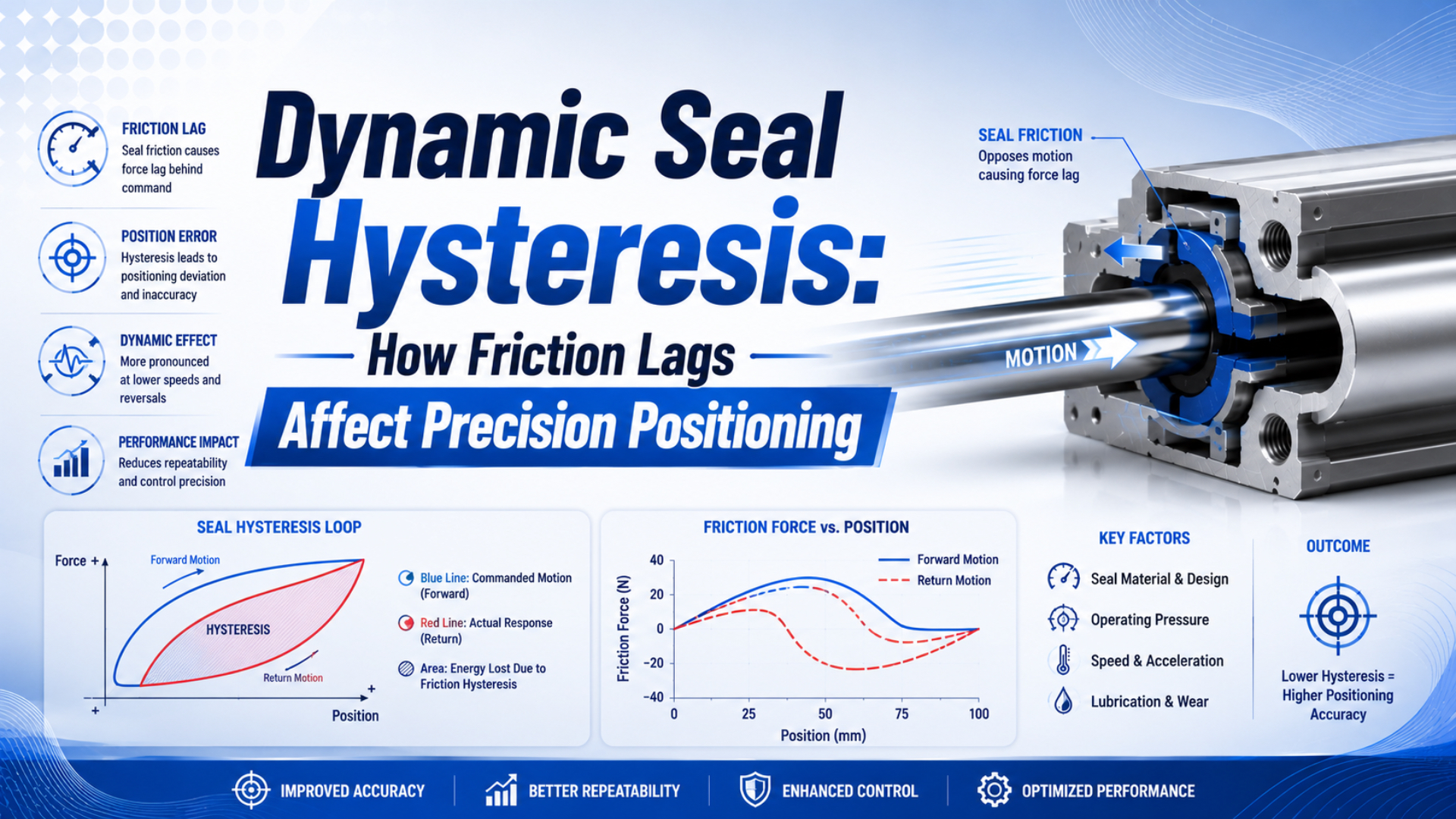
Dynamic seal hysteresis is direction- and history-dependent friction at a moving cylinder seal, observed when matched mechanical inputs produce different friction or displacement after opposite approaches. It is not a universal millimeter error. A 2014 pneumatic-cylinder experiment measured nonlinear pre-sliding force-displacement loops with nonlocal memory, showing why the previous motion history must be part of the test (Bo et al., 2014).
Positioning problems appear when that friction interacts with chamber pressure, air compressibility, load, valve behavior, guidance, and control logic. A position trace alone cannot identify the source. The useful diagnostic is a synchronized record of command, both chamber pressures, position, velocity, load, and time.
Key Takeaways
- Seal hysteresis, breakaway friction, stick-slip, and dynamic lag are related but different measurements.
- A 2026 study used position, velocity, two chamber pressures, and friction force on three cylinders.
- Estimate friction from a documented force balance, then compare matched direction, dwell, speed, pressure, and temperature conditions.
What Does Dynamic Seal Hysteresis Actually Mean?
A 2014 pre-sliding study controlled both chamber pressures and calculated friction from pressure and piston displacement. It found nonlinear spring behavior, nonlocal-memory hysteresis, and pressure-dependent loop size. Dynamic seal hysteresis therefore requires a declared force-displacement or friction-history test, not any unexplained gap between commanded and actual position (Bo et al., 2014).
Four terms need separate definitions:
- Pre-sliding hysteresis is the force-displacement loop produced by tiny reversible motion before sustained sliding develops.
- Breakaway friction is the peak resisting force that must be overcome after a declared dwell.
- Running friction is the resistance during sustained motion at a declared speed, pressure, direction, lubrication state, and temperature.
- Stick-slip is alternating sticking and slipping caused by the interaction of friction, stored pneumatic energy, load, and motion dynamics.
Dynamic lag is different again. It is a time-domain delay or phase difference between a command and a measured response. Valve flow, tubing, chamber volume, air compressibility, sensor filters, controller sampling, mass, and friction can all contribute. For example, a wide command-position loop at high speed does not prove that the seal itself has high quasi-static hysteresis.
The article on proportional pressure-control hysteresis explains command-pressure loops. The pneumatic Stribeck guide covers friction-speed maps. This article connects measured seal friction to the final positioning result without merging those tests.
Name the axes before naming the fault. A force-displacement loop, friction-velocity map, command-pressure loop, and command-position loop can all be called “hysteresis,” yet each includes a different physical chain. The ordered pair is part of the measurement.
The Force Balance Behind Friction-Induced Positioning Error
The 2026 stick-slip study estimated cylinder friction from both chamber pressures, effective areas, moving mass, and acceleration. Three tested cylinders showed different stick-slip forms as flow, pressure, load, and initial position changed. The result supports residual-force calculation instead of assigning every positioning deviation to a generic friction percentage (Ngoc et al., 2026).
For positive extension of a conventional double-acting, single-rod cylinder, one useful gauge-pressure force balance is:
is the signed residual friction force, and are synchronized chamber gauge pressures, and are the cap-end and rod-end effective areas, is the signed external load including gravity when applicable, is the moving mass, and is acceleration. The sign convention must remain unchanged through the test.
At very low speed, the inertial term may be small, but it should not be discarded before checking the data. Numerical differentiation can amplify encoder noise. The 2026 study derived acceleration from position and applied an offline low-pass filter, which means sensor resolution, sample rate, filter method, and phase treatment belong in the report.
Why can’t friction simply be multiplied by stroke length to predict positioning error? Because position follows the complete force and control balance. A local linear approximation may be written as:
is the local position shift, is the direction- or history-dependent friction change, and is the effective pneumatic, structural, load, and closed-loop stiffness around the operating point. This approximation applies only over a small region where that combined stiffness can be treated as locally linear.
The air-compressibility control guide explains why pneumatic stiffness changes with chamber pressure, volume, and piston position. Friction is one term in that position-dependent system, not a percentage of total stroke.
How Should Seal Friction Hysteresis Be Measured?
ISO 10099:2001 specifies final-examination tests and acceptance criteria for double-acting single-rod pneumatic cylinders. The 2026 research also repeated controlled tests on three cylinders. A positioning-hysteresis investigation likewise needs an explicit rig, sequence, stabilization rule, and safety boundary before loops or repeatability values can be compared (ISO 10099, 2001).
Use a restrained test setup with a defined safe state for electrical power loss, signal loss, and air loss. Stored pneumatic energy can move the axis after a valve command is removed. ISO 4414 system safeguards and the machine risk assessment remain applicable; the measurement plan does not replace guarding or load restraint.
Record these signals on one clock:
- Command to the valve or pressure regulator
- Supply pressure before the control element
- Cap-end chamber pressure
- Rod-end chamber pressure
- Position at the actuator and, when relevant, at the tooling datum
- Velocity and acceleration derived with a documented method
- External load or load-cell force
- Seal, air, and ambient temperature
Then declare the mechanical configuration: bore, rod diameter, stroke, piston position, mounting, guidance, payload, center of gravity, tubing, fittings, valve, flow-control settings, lubricant condition, seal profile, and dwell time before motion.
Use two complementary sequences:
- Settled reversal test: apply matched slow force or pressure steps from opposite directions, use a declared dwell criterion, and examine direction-dependent residual friction or displacement.
- Production-profile test: replay the actual command, payload, speed, and timing while recording overshoot, settling, approach direction, and cycle result.
In our experience, the most common missing channels are rod-end pressure and tooling-datum position. Without rod-end pressure, the opposing pneumatic force is guessed. Without tooling position, guide clearance or fixture flex may be mistaken for seal behavior.
Static Pre-Sliding Hysteresis and Dynamic Lag Are Different Tests
The 2014 study recorded nonlocal-memory hysteresis in pre-sliding force-displacement data. The 2026 study tracked alternating sticking and slipping over time. These related tests answer different questions: one measures tiny direction-dependent displacement before sustained sliding; the other follows pressure buildup, release, motion, and repeated stick-slip events (Bo et al., 2014; Ngoc et al., 2026).
For a quasi-static pre-sliding test, plot estimated friction force against piston displacement over matched reversals. Keep pressure levels, load, dwell, temperature, and displacement amplitude fixed. The loop width and shape describe that configuration. They do not directly specify the final positioning error of a controlled machine.
For a dynamic test, plot command, pressure, position, velocity, and friction estimate against time. Also inspect matched input-output plots at a declared command rate. Faster ramps can widen a loop through valve flow, chamber filling, filters, sampling, and inertia even if the settled friction path is unchanged.
Do not use loop area as an energy quantity unless the axes form a work-conjugate pair and units are retained. Force-displacement area can represent mechanical work over the declared cycle. Voltage-position or command-position area has no automatic energy interpretation.
Run the settled reversal test first. It establishes whether direction-dependent behavior remains after the pressure and position signals stabilize. Then run the production profile. The difference between those results shows how much loop width comes from rate-dependent system dynamics rather than settled seal friction.
Which Signals Separate Seal Friction from Other Positioning Faults?
Parker states that its friction-versus-pressure-and-velocity graph applies only to one seal in one application. Its handbook also lists wear-ring swelling, side load, valve pulsation, poor lubrication, external sliding surfaces, and trapped pressure as stick-slip causes. Eliminate competing load paths before assigning the fault to a seal (Parker O-Ring Handbook, accessed 2026).
| Observation | Seal-friction evidence | Competing cause | Measurement that separates them |
|---|---|---|---|
| Delay before first movement | Residual friction rises to a repeatable breakaway peak after dwell | Valve delay, low pilot pressure, restriction | Command, valve pressure, both chamber pressures, first-motion time |
| Low-speed stop-start motion | Pressure builds during stick and falls or redistributes during slip | Valve pulsation, controller limit cycle, guide binding | Pressure, position, velocity, valve command, guide force |
| Different endpoint by approach direction | Direction-dependent residual force near the target | Backlash, sensor mounting, stop compliance | Tooling position, cylinder position, both pressures, external force |
| Error grows as machine warms | Friction loop changes with measured seal temperature | Sensor drift, regulator drift, frame expansion | Temperature, calibrated position reference, pressure, friction estimate |
| One-sided seal wear | Friction differs with direction and load orientation | Misalignment, bearing clearance, side load | Wear pattern, alignment, guide reaction, unloaded friction test |
| Wide command-position loop at speed | Running friction may contribute | Air-path delay, flow saturation, filters, mass | Settled reversal test plus timed production trace |
A rod or piston seal is not the cylinder’s guide. The dynamic-versus-static seal guide separates sealing interfaces, while the force-loss diagnostic explains why both chamber pressures must be retained in the force balance.
From our work reviewing positioning faults, changing seal material before checking alignment and guide reaction often changes the symptom without identifying the load path. A no-load, mechanically aligned baseline is more useful than comparing two seals on a binding axis.
How Do Dwell, Pressure, Speed, Direction, and Temperature Change the Result?
A 2019 study varied seal cross-section, diameter, pressure, velocity, and stroke direction on commercial pneumatic hardware. Pressure had more influence than velocity, while piston seals accounted for 90% of measured friction in those test arrangements. Because the variables interacted, that percentage is configuration-specific, not a universal cylinder constant (Azzi et al., 2019).
Build the test matrix around variables that can change contact or the system force balance:
- Dwell: report the stationary time before breakaway. Parker notes that longer dwell can squeeze lubricant from the contact and allow the material to conform more closely to the surface.
- Pressure: test the actual chamber pressure range, not only plant supply. For example, pressure-energized profiles can change contact stress.
- Speed: separate breakaway, low-speed sliding, reversal, and production speed. Do not assign universal Stribeck regimes by velocity alone.
- Direction: retain extension and retraction as separate traces because effective areas, seal loading, guidance, and external forces can differ.
- Temperature: measure the seal or nearby barrel temperature rather than assuming ambient temperature represents the sliding contact.
- Lubrication history: document grease type, amount, relubrication, cleaning, dry-air exposure, and prior cycles.
- Wear and contamination: repeat the baseline only after recording seal condition, counterface damage, particles, and one-sided wear.
The 2026 experiments also found that higher airflow and supply pressure attenuated stick-slip gradually rather than eliminating it across all three tested cylinders. That is an important diagnostic warning. Raising pressure may change the symptom while increasing force and air demand; it does not prove that the seal or control problem is solved.
The stick-slip motion guide covers the broader instability. This article keeps the acceptance variable tied to the measured friction and position chain.
A Design and Control Strategy for Reducing Friction-Limited Error
SMC’s MQQ metal-seal catalog lists, for specified variants, 0.005 MPa minimum operating pressure and speeds from 0.5 to 500 mm/s, with some values marked reference-only. This is the right evidence pattern: low-friction claims belong to an exact construction, bore, load, pressure, speed, and test condition (SMC MQQ catalog, accessed 2026).
Use a layered correction sequence:
Correct the mechanical load path
Align the cylinder, guide, coupling, and tooling before changing controller gains. Remove unintended side load from the sealing surfaces. Measure position at the tooling datum when carriage clearance, fixture flex, or payload offset can move the part relative to the cylinder sensor.
Select the seal as a tested system
Match the profile, compound, counterface, groove, pressure, temperature, speed, stroke, lubricant, and contamination controls. “PTFE” or “polyurethane” alone does not specify friction. The 2019 study showed that cross-section and diameter interact with operating conditions.
Preserve the intended lubrication state
Use the lubricant and maintenance method approved for the exact seal assembly. Adding an airline lubricator to equipment designed for non-lubricated air can wash or dilute factory grease, while running a grease-dependent contact dry can raise breakaway and wear. Follow model documentation.
Reduce air-path delay without creating restriction
Short valve-to-cylinder lines reduce controlled volume, but a smaller tube can restrict mass flow. Verify both chamber pressures during motion. A pressure trace reveals whether the controller is fighting friction or waiting for the chamber force to build.
Apply compensation only after identifying the plant
Feedforward breakaway compensation, friction observers, gain scheduling, approach-direction logic, and integral control can improve response. Each method has limits. Excess compensation can create overshoot or limit cycles when load, temperature, lubrication, or seal condition changes.
In our experience, a repeatable one-direction approach is often the simplest improvement when the process allows it. The machine removes approach direction as a variable instead of asking the controller to invert an uncertain friction path near zero velocity.
How Should Precision Positioning Requirements Be Specified?
Festo’s DNCM datasheet lists travel resolution of 0.01 mm or better, soft-stop endpoint repeatability below 0.1 mm, and intermediate-position repeatability of ±2 mm. The values describe one configured product but answer different questions. Resolution, endpoint repeatability, and intermediate positioning therefore cannot substitute for one another (Festo DNCM datasheet).
Write the acceptance requirement around the process:
- Metric: accuracy, unidirectional repeatability, bidirectional repeatability, resolution, overshoot, settling time, velocity ripple, or force stability
- Datum: cylinder sensor, carriage, tooling, part feature, or external metrology frame
- Target positions: hard stop, soft-stop endpoint, or intermediate position
- Approach: one direction or both directions, including reversal distance
- Conditions: pressure, load, orientation, speed, dwell, temperature, lubrication, cycle history, and supply variation
- Statistics: number of repetitions, warm-up state, reported spread, outlier rule, and measurement uncertainty
- Dynamic result: command profile, overshoot, settling band, and allowed settling time
- Fault state: behavior after air loss, power loss, restart, and emergency stop
The repeatability-versus-accuracy guide defines those metrics in detail. For seal hysteresis, report the residual friction loop and the machine positioning result separately. One documents a suspected mechanism; the other determines whether the process passes.
The most defensible purchasing specification has two layers. The actuator layer defines the measured friction or breakaway test for the exact configuration. The machine layer defines part-position accuracy and repeatability under the production profile. A supplier can then prove the component without pretending that one seal number guarantees the entire machine.
Dynamic Seal Hysteresis FAQs: What Should Engineers Measure?
Parker separates break-out from running friction, while a 2014 pre-sliding study found nonlinear hysteresis before sustained motion. These FAQs keep five confused measurements apart: friction history, pressure-derived residual force, positioning repeatability, lubrication behavior, and controller compensation. Each answer assumes declared load, direction, pressure, temperature, and measurement location (Parker O-Ring Handbook, accessed 2026).
Can a position trace alone prove that seal hysteresis is the problem?
No. Position reveals the outcome, not the cause. Record command, supply pressure, both chamber pressures, load, and tooling position on the same time base. Compare a settled reversal test with the production profile. Valve delay, air compressibility, guide binding, backlash, sensor movement, and seal friction can produce similar position traces.
How is pneumatic cylinder friction estimated from pressure measurements?
Use a signed force balance with synchronized cap-end and rod-end pressures, their effective areas, external load, moving mass, and acceleration. The pressure reference and positive direction must be documented. At very low speed the inertial term may be small, but encoder differentiation and filtering should still be reported before it is neglected.
Does a low-friction seal guarantee better positioning accuracy?
No. Lower and more repeatable friction can reduce one disturbance, but accuracy also depends on air stiffness, valve behavior, control strategy, load, guidance, structure, sensor mounting, and target location. Compare exact product data under relevant conditions, then verify the installed machine at its tooling datum and production approach speed.
Should unidirectional and bidirectional repeatability be tested separately?
Yes. A one-direction test removes approach direction as a variable, while a bidirectional test exposes direction-dependent friction, backlash, compliance, and controller behavior. State the reversal distance, dwell, target, load, pressure, speed, warm-up condition, number of repetitions, and reported statistical spread so the two results remain comparable.
Can software compensation eliminate dynamic seal hysteresis?
Compensation can reduce predictable friction effects, but it cannot remove changing lubrication, wear, temperature, valve saturation, sensor limitations, or mechanical binding. Identify the friction path first, then validate compensation across the permitted operating envelope. Safety and load-holding functions must remain independent of the accuracy controller and its friction model.
Sources and technical references
- Bo et al.: Experimental investigation of friction behavior in pre-sliding regime for pneumatic cylinder
- Ngoc, Pham, and Xuan: Experimental and System-Level Simulation Study of Stick-Slip Characteristics in Pneumatic Cylinders
- Azzi et al.: Experimental study of friction in pneumatic seals
- Parker O-Ring Handbook
- Parker Performance Sealing Products: friction and stick-slip guidance
- SMC MQQ/MQM/MQP low-friction cylinder catalog
- ISO 10099:2001: Pneumatic cylinders, final examination and acceptance criteria
- ISO 4414:2010: Pneumatic fluid power, general rules and safety requirements
- Festo DNCM positioning-drive datasheet